1989 FORD FIESTA auxiliary battery
[x] Cancel search: auxiliary batteryPage 236 of 296
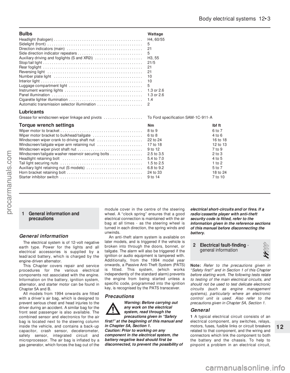
BulbsWattage
Headlight (halogen) . . . . . . . . . . . . . . . . . . . . . . . . . . . . . . . . . . . .\
. . . . . H4, 60/55
Sidelight (front) . . . . . . . . . . . . . . . . . . . . . . . . . . . . . . . . . . . .\
. . . . . . . . 5
Direction indicators (main) . . . . . . . . . . . . . . . . . . . . . . . . . . . . . . . . . . . 21
Side direction indicator repeaters . . . . . . . . . . . . . . . . . . . . . . . . . . . . . . 5
Auxiliary driving and foglights (S and XR2i) . . . . . . . . . . . . . . . . . . . . . . H3, 55
Stop/tail light . . . . . . . . . . . . . . . . . . . . . . . . . . . . . . . . . . . .\
. . . . . . . . . . 21/5
Rear foglight . . . . . . . . . . . . . . . . . . . . . . . . . . . . . . . . . . . .\
. . . . . . . . . . 21
Reversing light . . . . . . . . . . . . . . . . . . . . . . . . . . . . . . . . . . . .\
. . . . . . . . 21
Number plate light . . . . . . . . . . . . . . . . . . . . . . . . . . . . . . . . . . . .\
. . . . . 10
Interior light . . . . . . . . . . . . . . . . . . . . . . . . . . . . . . . . . . . .\
. . . . . . . . . . . 10
Luggage compartment light . . . . . . . . . . . . . . . . . . . . . . . . . . . . . . . . . . 5
Instrument warning lights . . . . . . . . . . . . . . . . . . . . . . . . . . . . . . . . . . . .\
1.3 or 2.6
Panel illumination . . . . . . . . . . . . . . . . . . . . . . . . . . . . . . . . . . . .\
. . . . . . 1.3 or 2.6
Cigarette lighter illumination . . . . . . . . . . . . . . . . . . . . . . . . . . . . . . . . . . 1.4
Automatic transmission selector illumination . . . . . . . . . . . . . . . . . . . . . 2
Lubricants
Grease for windscreen wiper linkage and pivots . . . . . . . . . . . . . . . . . . To Ford specification SAM-1C-911-A
Torque wrench settingsNm lbf ft
Wiper motor to bracket . . . . . . . . . . . . . . . . . . . . . . . . . . . . . . . . . . . .\
. . 8 to 9 6 to 7
Wiper motor bracket to bulkhead/tailgate . . . . . . . . . . . . . . . . . . . . . . . 6 to 8 4 to 6
Windscreen wiper crank to driving shaft nut . . . . . . . . . . . . . . . . . . . . . 22 to 24 16 to 18
Windscreen/tailgate wiper arm retaining nut . . . . . . . . . . . . . . . . . . . . . 17 to 18 12 to 13
Windscreen wiper pivot shaft nut . . . . . . . . . . . . . . . . . . . . . . . . . . . . . . 9 to 12 7 to 9
Windscreen/tailgate washer reservoir securing bolts . . . . . . . . . . . . . . . 2.5 to 3.5 2 to 3
Headlight retaining bolt . . . . . . . . . . . . . . . . . . . . . . . . . . . . . . . . . . . .\
. 5.4 to 7.0 4 to 5
Tail light securing nuts . . . . . . . . . . . . . . . . . . . . . . . . . . . . . . . . . . . .\
. . 1.5 to 2.5 1 to 2
Auxiliary light retaining nut (S models) . . . . . . . . . . . . . . . . . . . . . . . . . . 6.8 to 9.2 5 to 7
Horn bracket retaining bolt . . . . . . . . . . . . . . . . . . . . . . . . . . . . . . . . . . . 24 to 33 18 to 24
Starter inhibitor switch . . . . . . . . . . . . . . . . . . . . . . . . . . . . . . . . . . . .\
. . 9 to 14 7 to 10
Body electrical systems 12•3
12
1595Ford Fiesta Remake
1 General information and
precautions
General information
The electrical system is of 12-volt negative
earth type. Power for the lights and all
electrical accessories is supplied by a
lead/acid battery, which is charged by the
engine-driven alternator.
This Chapter covers repair and service
procedures for the various electrical
components not associated with the engine.
Information on the battery, ignition system,
alternator, and starter motor can be found in
Chapter 5A and B.
All models from 1994 onwards are fitted
with a driver’s air bag, which is designed to
prevent serious chest and head injuries to the
driver during an accident. A similar bag for the
front seat passenger is also available. The
combined sensor and electronics for the air
bag is located next to the steering column
inside the vehicle, and contains a back-up
capacitor, crash sensor, decelerometer,
safety sensor, integrated circuit and
microprocessor. The air bag is inflated by a
gas generator, which forces the bag out of the module cover in the centre of the steering
wheel. A “clock spring” ensures that a good
electrical connection is maintained with the air
bag at all times - as the steering wheel is
turned in each direction, the spring winds and
unwinds.
An anti-theft alarm system is available on
later models, and is triggered if the vehicle is
broken into through the doors, bonnet, or
tailgate. The alarm will also be triggered if the
ignition or audio equipment is tampered with.
Additionally, from the 1994 model year
onwards, a Passive Anti-Theft System (PATS)
is fitted. This system, (which works
independently of the standard alarm) prevents
the engine from being started unless a
specific code, programmed into the ignition
key, is recognised by the PATS transceiver.
Precautions
Warning: Before carrying out
any work on the electrical
system, read through the
precautions given in “Safety
first!” at the beginning of this manual and
in Chapter 5A, Section 1.
Caution: Prior to working on any
component in the electrical system, the
battery negative lead should first be
disconnected, to prevent the possibility of electrical short-circuits and/or fires. If a
radio/cassette player with anti-theft
security code is fitted, refer to the
information given in the reference sections
of this manual before disconnecting the
battery.
2 Electrical fault-finding
-
general information
2
Note: Refer to the precautions given in
“Safety first!” and in Section 1 of this Chapter
before starting work. The following tests relate
to testing of the main electrical circuits, and
should not be used to test delicate electronic
circuits (such as engine management
systems), particularly where an electronic
control unit is used. Also refer to the
precautions given in Chapter 5A, Section 1.
General
1 A typical electrical circuit consists of an
electrical component, any switches, relays,
motors, fuses, fusible links or circuit breakers
related to that component, and the wiring and
connectors which link the component to both
the battery and the chassis. To help to
pinpoint a problem in an electrical circuit,
procarmanuals.com
http://vnx.su
Page 243 of 296
8Refitting is a reversal of the removal
procedure.
Front direction indicator side
repeater
9 Remove the appropriate front wheel arch
liner as described in Chapter 11.
10 Remove the appropriate sill scuff plate as
described in Chapter 11, and release the clip
securing the insulation to the panel forward of
the lower A-pillar.
11 Disconnect the supply lead connector and
the earth lead, then release their grommet
from its panel location.
12 From outside the vehicle, twist the light
assembly to release it, then withdraw it and its
leads.
13 Refitting is a reversal of the removal
procedure, ensuring that the grommet is
seated correctly in its panel location.
Rear light cluster
14 Disconnect the multi-plug from the
bulbholder, then press the retaining lugs on
the bulbholder together and remove it (see
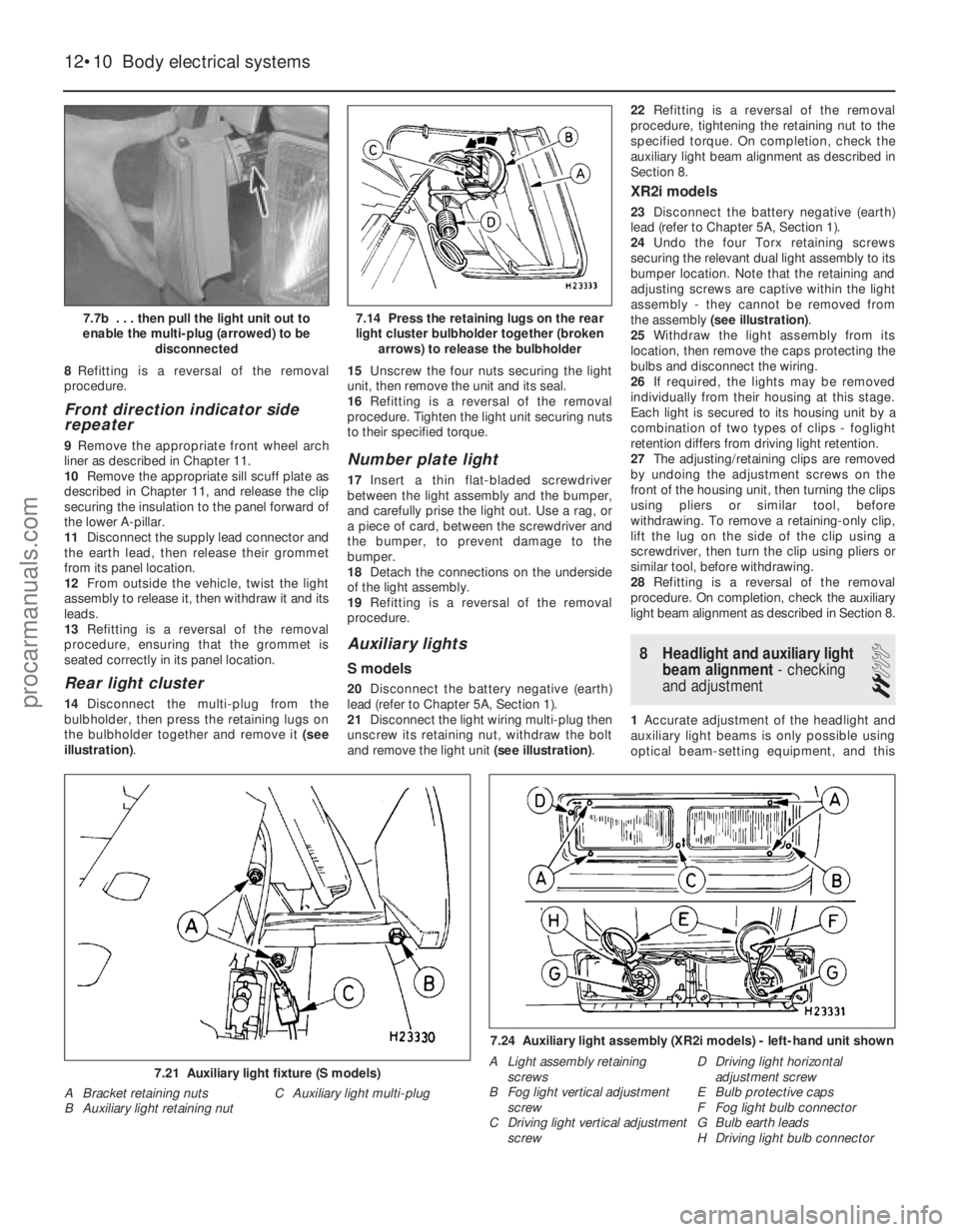
illustration) . 15
Unscrew the four nuts securing the light
unit, then remove the unit and its seal.
16 Refitting is a reversal of the removal
procedure. Tighten the light unit securing nuts
to their specified torque.
Number plate light
17 Insert a thin flat-bladed screwdriver
between the light assembly and the bumper,
and carefully prise the light out. Use a rag, or
a piece of card, between the screwdriver and
the bumper, to prevent damage to the
bumper.
18 Detach the connections on the underside
of the light assembly.
19 Refitting is a reversal of the removal
procedure.
Auxiliary lights
S models
20 Disconnect the battery negative (earth)
lead (refer to Chapter 5A, Section 1).
21 Disconnect the light wiring multi-plug then
unscrew its retaining nut, withdraw the bolt
and remove the light unit (see illustration).22
Refitting is a reversal of the removal
procedure, tightening the retaining nut to the
specified torque. On completion, check the
auxiliary light beam alignment as described in
Section 8.
XR2i models
23 Disconnect the battery negative (earth)
lead (refer to Chapter 5A, Section 1).
24 Undo the four Torx retaining screws
securing the relevant dual light assembly to its
bumper location. Note that the retaining and
adjusting screws are captive within the light
assembly - they cannot be removed from
the assembly (see illustration) .
25 Withdraw the light assembly from its
location, then remove the caps protecting the
bulbs and disconnect the wiring.
26 If required, the lights may be removed
individually from their housing at this stage.
Each light is secured to its housing unit by a
combination of two types of clips - foglight
retention differs from driving light retention.
27 The adjusting/retaining clips are removed
by undoing the adjustment screws on the
front of the housing unit, then turning the clips
using pliers or similar tool, before
withdrawing. To remove a retaining-only clip,
lift the lug on the side of the clip using a
screwdriver, then turn the clip using pliers or
similar tool, before withdrawing.
28 Refitting is a reversal of the removal
procedure. On completion, check the auxiliary
light beam alignment as described in Section 8.
8 Headlight and auxiliary light
beam alignment - checking
and adjustment
2
1 Accurate adjustment of the headlight and
auxiliary light beams is only possible using
optical beam-setting equipment, and this
12•10 Body electrical systems
7.24 Auxiliary light assembly (XR2i models) - left-hand unit shown
A Light assembly retaining screws
B Fog light vertical adjustment screw
C Driving light vertical adjustment screw D Driving light horizontal
adjustment screw
E Bulb protective caps
F Fog light bulb connector
G Bulb earth leads
H Driving light bulb connector
7.21 Auxiliary light fixture (S models)
A Bracket retaining nuts C Auxiliary light multi-plug
B Auxiliary light retaining nut
7.14 Press the retaining lugs on the rear
light cluster bulbholder together (broken arrows) to release the bulbholder7.7b . . . then pull the light unit out to
enable the multi-plug (arrowed) to be disconnected
1595Ford Fiesta Remakeprocarmanuals.com
http://vnx.su
Page 244 of 296
work should therefore be carried out by a
Ford dealer or service station with the
necessary facilities.
2Temporary adjustment can be made when
the headlight has been removed and refitted,
or to compensate for normal adjustment
whenever a heavy load is being carried. Turn
the adjustment screws at the rear of the
headlight unit to make the adjustment (see
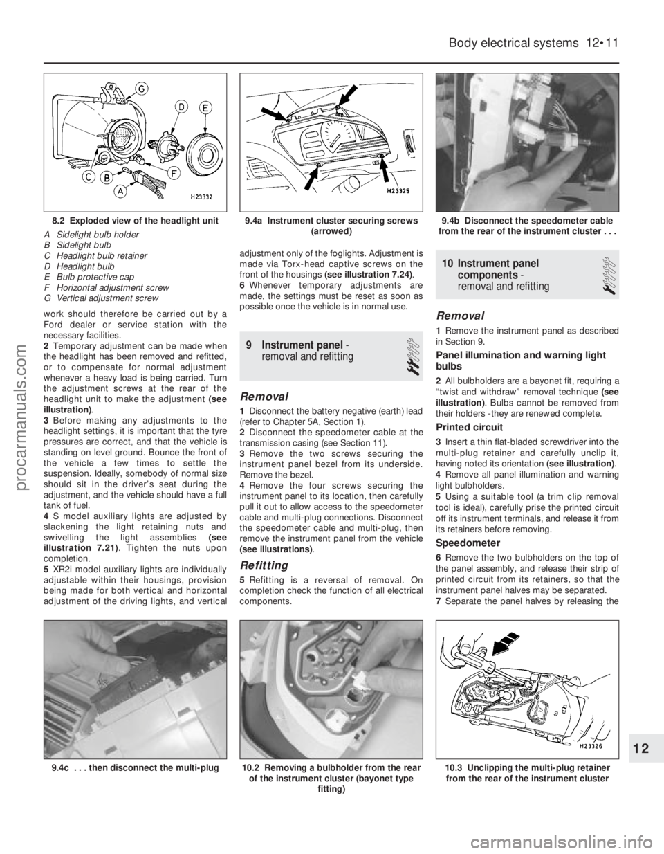
illustration) .
3 Before making any adjustments to the
headlight settings, it is important that the tyre
pressures are correct, and that the vehicle is
standing on level ground. Bounce the front of
the vehicle a few times to settle the
suspension. Ideally, somebody of normal size
should sit in the driver’s seat during the
adjustment, and the vehicle should have a full
tank of fuel.
4 S model auxiliary lights are adjusted by
slackening the light retaining nuts and
swivelling the light assemblies (see
illustration 7.21) . Tighten the nuts upon
completion.
5 XR2i model auxiliary lights are individually
adjustable within their housings, provision
being made for both vertical and horizontal
adjustment of the driving lights, and vertical adjustment only of the foglights. Adjustment is
made via Torx-head captive screws on the
front of the housings
(see illustration 7.24) .
6 Whenever temporary adjustments are
made, the settings must be reset as soon as
possible once the vehicle is in normal use.
9 Instrument panel -
removal and refitting
2
Removal
1 Disconnect the battery negative (earth) lead
(refer to Chapter 5A, Section 1).
2 Disconnect the speedometer cable at the
transmission casing (see Section 11).
3 Remove the two screws securing the
instrument panel bezel from its underside.
Remove the bezel.
4 Remove the four screws securing the
instrument panel to its location, then carefully
pull it out to allow access to the speedometer
cable and multi-plug connections. Disconnect
the speedometer cable and multi-plug, then
remove the instrument panel from the vehicle
(see illustrations) .
Refitting
5Refitting is a reversal of removal. On
completion check the function of all electrical
components.
10 Instrument panel
components -
removal and refitting
1
Removal
1 Remove the instrument panel as described
in Section 9.
Panel illumination and warning light
bulbs
2 All bulbholders are a bayonet fit, requiring a
“twist and withdraw” removal technique (see
illustration) . Bulbs cannot be removed from
their holders -they are renewed complete.
Printed circuit
3 Insert a thin flat-bladed screwdriver into the
multi-plug retainer and carefully unclip it,
having noted its orientation (see illustration).
4 Remove all panel illumination and warning
light bulbholders.
5 Using a suitable tool (a trim clip removal
tool is ideal), carefully prise the printed circuit
off its instrument terminals, and release it from
its retainers before removing.
Speedometer
6 Remove the two bulbholders on the top of
the panel assembly, and release their strip of
printed circuit from its retainers, so that the
instrument panel halves may be separated.
7 Separate the panel halves by releasing the
Body electrical systems 12•11
9.4b Disconnect the speedometer cable
from the rear of the instrument cluster . . .9.4a Instrument cluster securing screws (arrowed)8.2 Exploded view of the headlight unit
A Sidelight bulb holder
B Sidelight bulb
C Headlight bulb retainer
D Headlight bulb
E Bulb protective cap
F Horizontal adjustment screw
G Vertical adjustment screw
10.3 Unclipping the multi-plug retainer from the rear of the instrument cluster10.2 Removing a bulbholder from the rear of the instrument cluster (bayonet type
fitting)9.4c . . . then disconnect the multi-plug
12
1595Ford Fiesta Remakeprocarmanuals.com
http://vnx.su
Page 286 of 296
1595 Ford Fiesta Remake
REF•20Fault finding
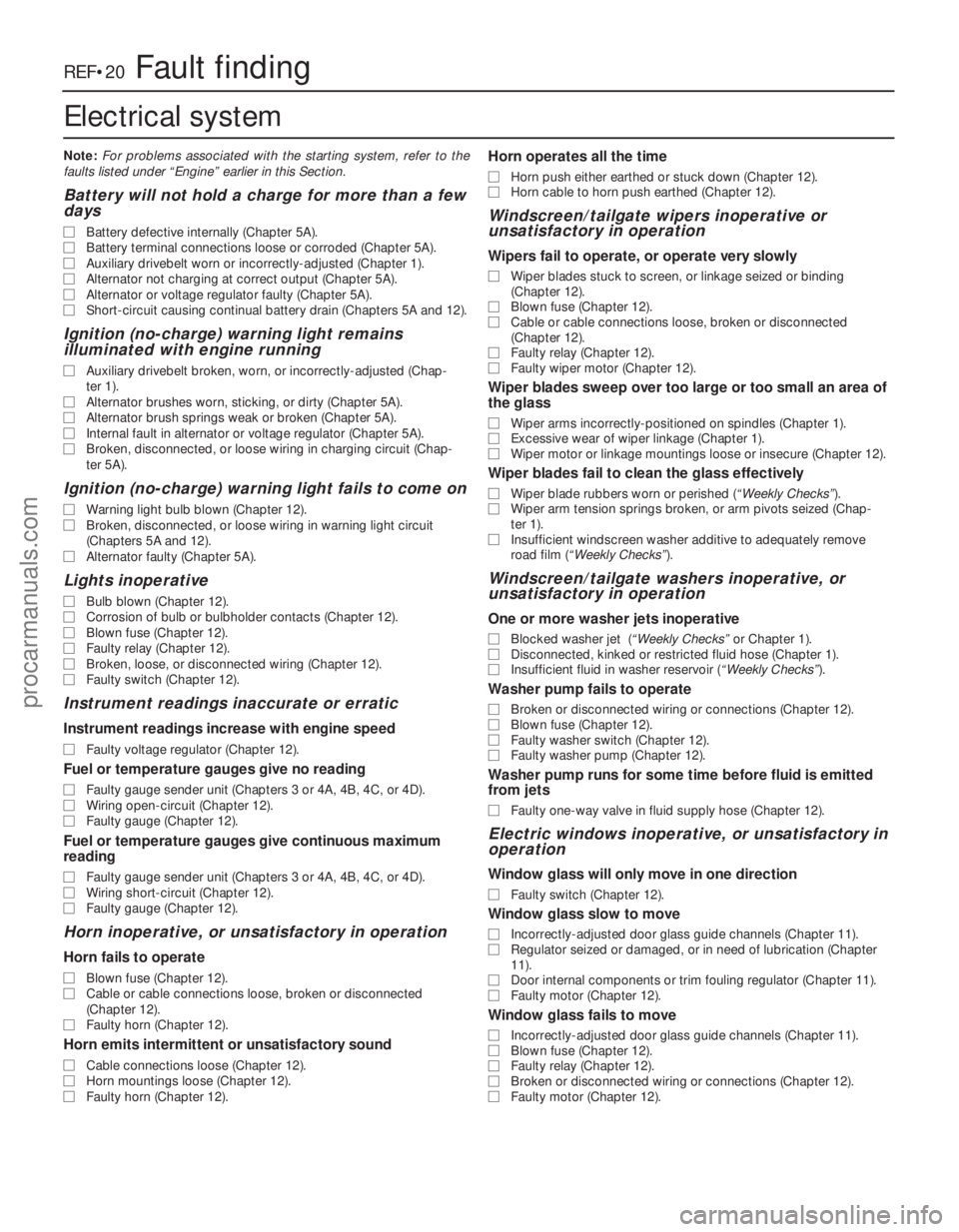
Electrical system
Note:For problems associated with the starting system, refer to the
faults listed under “Engine” earlier in this Section.
Battery will not hold a charge for more than a few
days
m m Battery defective internally (Chapter 5A).
m
m Battery terminal connections loose or corroded (Chapter 5A).
m
m Auxiliary drivebelt worn or incorrectly-adjusted (Chapter 1).
m
m Alternator not charging at correct output (Chapter 5A).
m
m Alternator or voltage regulator faulty (Chapter 5A).
m
m Short-circuit causing continual battery drain (Chapters 5A and 12).
Ignition (no-charge) warning light remains
illuminated with engine running
m mAuxiliary drivebelt broken, worn, or incorrectly-adjusted (Chap-
ter 1).
m m Alternator brushes worn, sticking, or dirty (Chapter 5A).
m
m Alternator brush springs weak or broken (Chapter 5A).
m
m Internal fault in alternator or voltage regulator (Chapter 5A).
m
m Broken, disconnected, or loose wiring in charging circuit (Chap-
ter 5A).
Ignition (no-charge) warning light fails to come on
m mWarning light bulb blown (Chapter 12).
m
m Broken, disconnected, or loose wiring in warning light circuit
(Chapters 5A and 12).
m m Alternator faulty (Chapter 5A).
Lights inoperative
m
mBulb blown (Chapter 12).
m
m Corrosion of bulb or bulbholder contacts (Chapter 12).
m
m Blown fuse (Chapter 12).
m
m Faulty relay (Chapter 12).
m
m Broken, loose, or disconnected wiring (Chapter 12).
m
m Faulty switch (Chapter 12).
Instrument readings inaccurate or erratic
Instrument readings increase with engine speed
m
mFaulty voltage regulator (Chapter 12).
Fuel or temperature gauges give no reading
m
mFaulty gauge sender unit (Chapters 3 or 4A, 4B, 4C, or 4D).
m
m Wiring open-circuit (Chapter 12).
m
m Faulty gauge (Chapter 12).
Fuel or temperature gauges give continuous maximum
reading
m mFaulty gauge sender unit (Chapters 3 or 4A, 4B, 4C, or 4D).
m
m Wiring short-circuit (Chapter 12).
m
m Faulty gauge (Chapter 12).
Horn inoperative, or unsatisfactory in operation
Horn fails to operate
m
mBlown fuse (Chapter 12).
m
m Cable or cable connections loose, broken or disconnected
(Chapter 12).
m m Faulty horn (Chapter 12).
Horn emits intermittent or unsatisfactory sound
m
mCable connections loose (Chapter 12).
m
m Horn mountings loose (Chapter 12).
m
m Faulty horn (Chapter 12).
Horn operates all the time
m
mHorn push either earthed or stuck down (Chapter 12).
m
m Horn cable to horn push earthed (Chapter 12).
Windscreen/tailgate wipers inoperative or
unsatisfactory in operation
Wipers fail to operate, or operate very slowly
m mWiper blades stuck to screen, or linkage seized or binding
(Chapter 12).
m m Blown fuse (Chapter 12).
m
m Cable or cable connections loose, broken or disconnected
(Chapter 12).
m m Faulty relay (Chapter 12).
m
m Faulty wiper motor (Chapter 12).
Wiper blades sweep over too large or too small an area of
the glass
m mWiper arms incorrectly-positioned on spindles (Chapter 1).
m
m Excessive wear of wiper linkage (Chapter 1).
m
m Wiper motor or linkage mountings loose or insecure (Chapter 12).
Wiper blades fail to clean the glass effectively
m
mWiper blade rubbers worn or perished ( “Weekly Checks”).
m
m Wiper arm tension springs broken, or arm pivots seized (Chap-
ter 1).
m m Insufficient windscreen washer additive to adequately remove
road film ( “Weekly Checks” ).
Windscreen/tailgate washers inoperative, or
unsatisfactory in operation
One or more washer jets inoperative
m mBlocked washer jet ( “Weekly Checks”or Chapter 1).
m
m Disconnected, kinked or restricted fluid hose (Chapter 1).
m
m Insufficient fluid in washer reservoir ( “Weekly Checks”).
Washer pump fails to operate
m
mBroken or disconnected wiring or connections (Chapter 12).
m
m Blown fuse (Chapter 12).
m
m Faulty washer switch (Chapter 12).
m
m Faulty washer pump (Chapter 12).
Washer pump runs for some time before fluid is emitted
from jets
m mFaulty one-way valve in fluid supply hose (Chapter 12).
Electric windows inoperative, or unsatisfactory in
operation
Window glass will only move in one direction
m mFaulty switch (Chapter 12).
Window glass slow to move
m
mIncorrectly-adjusted door glass guide channels (Chapter 11).
m
m Regulator seized or damaged, or in need of lubrication (Chapter
11).
m m Door internal components or trim fouling regulator (Chapter 11).
m
m Faulty motor (Chapter 12).
Window glass fails to move
m
mIncorrectly-adjusted door glass guide channels (Chapter 11).
m
m Blown fuse (Chapter 12).
m
m Faulty relay (Chapter 12).
m
m Broken or disconnected wiring or connections (Chapter 12).
m
m Faulty motor (Chapter 12).
procarmanuals.com
http://vnx.su
Page 293 of 296
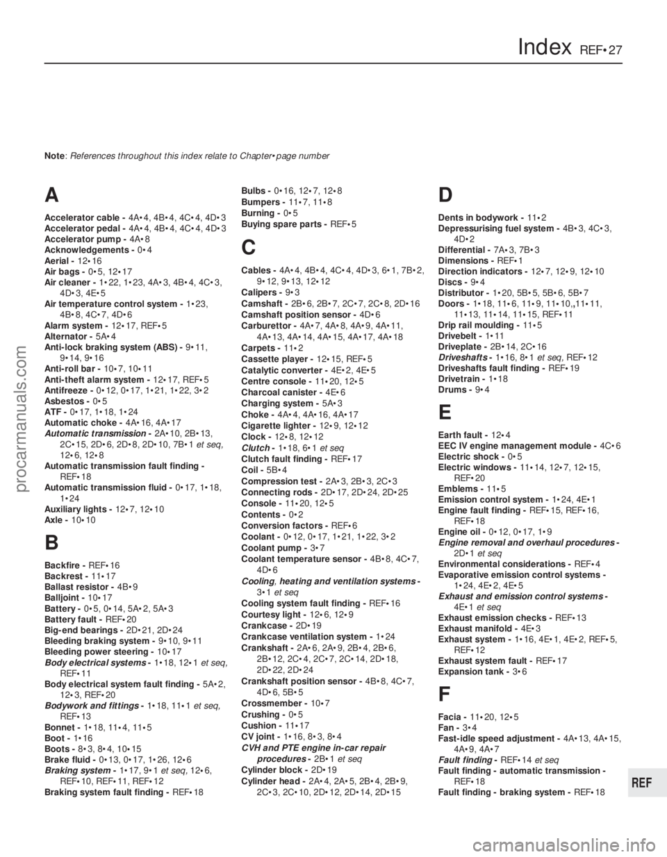
1595 Ford Fiesta Remake
IndexREF•27
REF
Note: References throughout this index relate to Chapter•page number
A
Accelerator cable -4A•4, 4B•4, 4C•4, 4D•3
Accelerator pedal - 4A•4, 4B•4, 4C•4, 4D•3
Accelerator pump - 4A•8
Acknowledgements - 0•4
Aerial - 12•16
Air bags - 0•5, 12•17
Air cleaner - 1•22, 1•23, 4A•3, 4B•4, 4C•3,
4D•3, 4E•5
Air temperature control system - 1•23,
4B•8, 4C•7, 4D•6
Alarm system - 12•17, REF• 5
Alternator - 5A•4
Anti-lock braking system (ABS) - 9•11,
9•14, 9•16
Anti-roll bar - 10•7, 10•11
Anti-theft alarm system - 12•17, REF•5
Antifreeze - 0•12, 0•17, 1•21, 1•22, 3•2
Asbestos - 0•5
ATF - 0•17, 1•18, 1•24
Automatic choke - 4A•16, 4A•17
Automatic transmission -2A•10, 2B•13,
2C•15, 2D•6, 2D•8, 2D•10, 7B•1 et seq,
12 •6, 12 •8
Automatic transmission fault finding - REF• 18
Automatic transmission fluid - 0•17, 1•18,
1•24
Auxiliary lights - 12•7, 12•10
Axle - 10•10
B
Backfire - REF•16
Backrest - 11•17
Ballast resistor - 4B•9
Balljoint - 10•17
Battery - 0•5, 0•14, 5A•2, 5A•3
Battery fault - REF•20
Big-end bearings - 2D•21, 2D•24
Bleeding braking system - 9•10, 9•11
Bleeding power steering - 10•17
Body electrical systems -1•18, 12 •1et seq,
REF• 11
Body electrical system fault finding - 5A•2,
12 •3, REF •20
Bodywork and fittings -1•18, 11 •1et seq,
REF• 13
Bonnet - 1•18, 11•4,11•5
Boot - 1•16
Boots - 8•3, 8•4, 10 •15
Brake fluid - 0•13, 0•17, 1•26, 12 •6
Braking system -1•17, 9•1 et seq, 12•6,
REF• 10, REF•11, REF• 12
Braking system fault finding - REF•18 Bulbs -
0•16, 12 •7,12•8
Bumpers - 11•7, 11•8
Burning - 0•5
Buying spare parts - REF•5
C
Cables -4A•4, 4B•4, 4C•4, 4D•3, 6•1, 7B•2,
9•12, 9•13, 12 •12
Calipers - 9•3
Camshaft - 2B•6, 2B•7, 2C•7, 2C•8, 2D•16
Camshaft position sensor - 4D•6
Carburettor - 4A•7, 4A•8, 4A•9, 4A•11,
4A•13, 4A•14, 4A•15, 4A•17, 4A•18
Carpets - 11•2
Cassette player - 12•15, REF •5
Catalytic converter - 4E•2, 4E•5
Centre console - 11•20, 12 •5
Charcoal canister - 4E•6
Charging system - 5A•3
Choke - 4A•4, 4A•16, 4A•17
Cigarette lighter - 12•9, 12 •12
Clock - 12•8, 12•12
Clutch -1•18, 6•1 et seq
Clutch fault finding - REF•17
Coil - 5B•4
Compression test - 2A•3, 2B•3, 2C•3
Connecting rods - 2D•17, 2D•24, 2D•25
Console - 11•20, 12•5
Contents - 0•2
Conversion factors - REF•6
Coolant - 0•12, 0•17, 1•21, 1•22, 3•2
Coolant pump - 3•7
Coolant temperature sensor - 4B•8, 4C•7,
4D•6
Cooling ,heating and ventilation systems -
3•1 et seq
Cooling system fault finding - REF•16
Courtesy light - 12•6, 12•9
Crankcase - 2D•19
Crankcase ventilation system - 1•24
Crankshaft - 2A•6, 2A•9, 2B•4, 2B•6,
2B•12, 2C•4, 2C•7, 2C•14, 2D•18,
2D•22, 2D•24
Crankshaft position sensor - 4B•8, 4C•7,
4D•6, 5B•5
Crossmember - 10•7
Crushing - 0•5
Cushion - 11•17
CV joint - 1•16, 8•3, 8•4
CVH and PTE engine in-car repair
procedures -2B•1 et seq
Cylinder block - 2D•19
Cylinder head - 2A•4, 2A•5, 2B•4, 2B•9,
2C•3, 2C•10, 2D•12, 2D•14, 2D•15
D
Dents in bodywork - 11•2
Depressurising fuel system - 4B•3, 4C•3,
4D•2
Differential - 7A•3, 7B•3
Dimensions - REF•1
Direction indicators - 12•7, 12•9, 12•10
Discs - 9•4
Distributor - 1•20, 5B•5, 5B•6, 5B•7
Doors - 1•18, 11• 6,11•9, 11 •10,,11 •11,
11 •13, 11•14, 11•15, REF •11
Drip rail moulding - 11•5
Drivebelt - 1•11
Driveplate - 2B•14, 2C•16
Driveshafts -1•16, 8•1 et seq,REF•12
Driveshafts fault finding - REF•19
Drivetrain - 1•18
Drums - 9•4
E
Earth fault - 12•4
EEC IV engine management module - 4C•6
Electric shock - 0•5
Electric windows - 11•14, 12 •7, 12•15,
REF•20
Emblems - 11•5
Emission control system - 1•24, 4E•1
Engine fault finding - REF•15, REF•16,
REF •18
Engine oil - 0•12, 0•17, 1•9
Engine removal and overhaul procedures -
2D•1 et seq
Environmental considerations - REF•4
Evaporative emission control systems - 1•24, 4E•2, 4E•5
Exhaust and emission control systems -
4E•1 et seq
Exhaust emission checks - REF•13
Exhaust manifold - 4E•3
Exhaust system - 1•16, 4E•1, 4E•2, REF •5,
REF •12
Exhaust system fault - REF•17
Expansion tank - 3•6
F
Facia - 11•20, 12 •5
Fan - 3•4
Fast-idle speed adjustment - 4A•13, 4A•15,
4A•9, 4A•7
Fault finding - REF•14et seq
Fault finding - automatic transmission -
REF •18
Fault finding - braking system - REF•18
procarmanuals.com
http://vnx.su