1989 FORD FIESTA compression ratio
[x] Cancel search: compression ratioPage 128 of 296
The seal ring must be renewed whenever the
pump/sender unit is withdrawn from the tank.
Refitting
4Refit in the reverse order of removal. Lightly
coat the new unit seal ring with grease to ease
fitting, and ensure that the seal is not
distorted as the unit is fitted into position.
Insert the unit so that the lug of the unit is in
engagement with the slot in the tank aperture,
then turn the unit to lock and secure.
10 Fuel tank ventilation tube -
removal and refitting
3
Refer to Part A, Section 10, but note that on
models with evaporative emission control, the
ventilation tube connects to the combined
roll-over/anti-trickle-fill valve assembly but,
instead of venting to atmosphere, a further
tube runs the length of the vehicle to a carbon
canister in the front right-hand corner of the
engine compartment. Further information on the evaporative
emission control system is contained in Part E
of this Chapter.
11 Fuel tank filler pipe -
removal and refitting
3
Refer to Part A, Section 11.
12 Fuel cut-off switch -
removal and refitting
2
Removal
1 Disconnect the battery negative (earth) lead
(refer to Chapter 5A, Section 1).
2 Remove the left-hand sill scuff plate as
described in Chapter 11, Section 42. 3
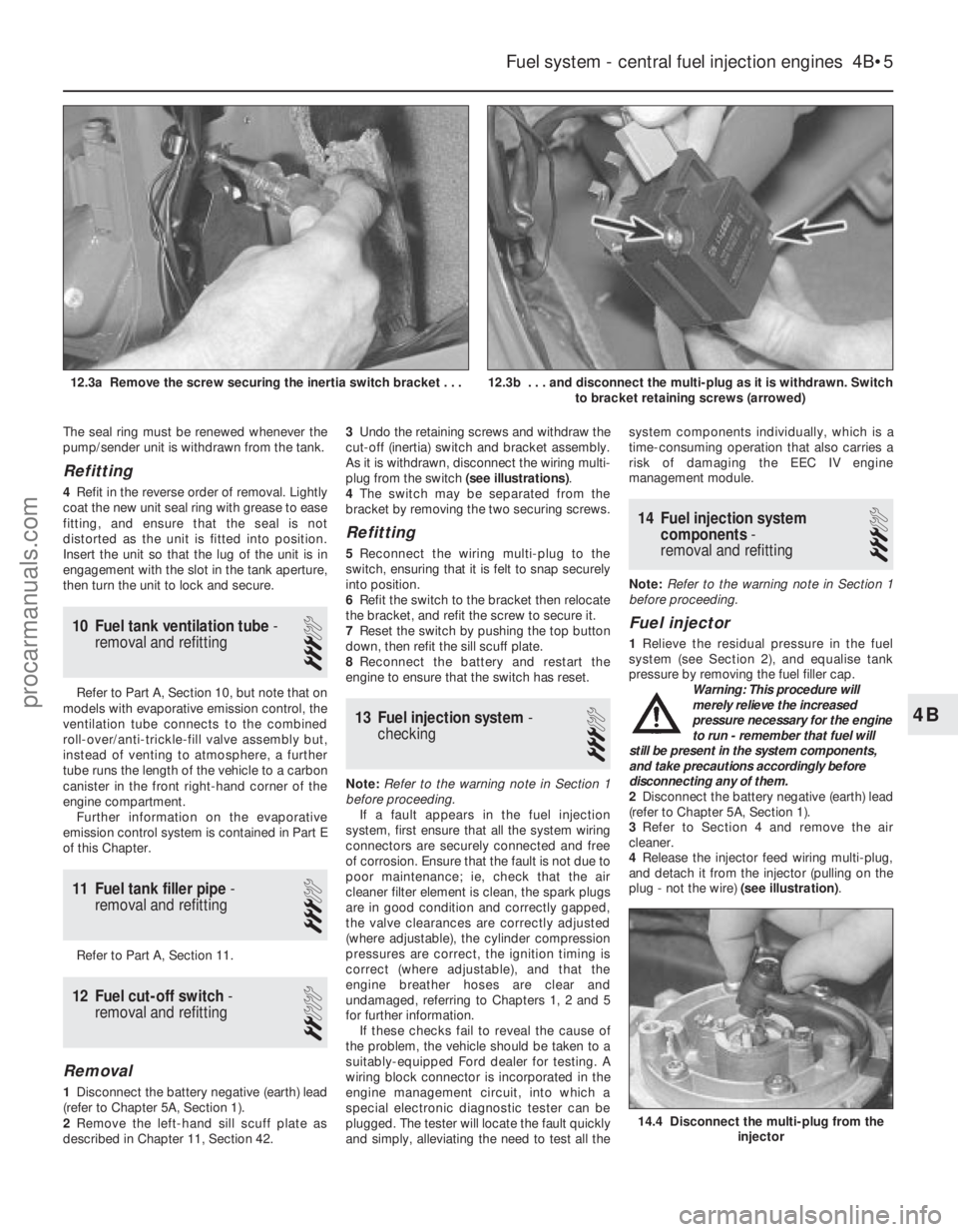
Undo the retaining screws and withdraw the
cut-off (inertia) switch and bracket assembly.
As it is withdrawn, disconnect the wiring multi-
plug from the switch (see illustrations).
4 The switch may be separated from the
bracket by removing the two securing screws.
Refitting
5 Reconnect the wiring multi-plug to the
switch, ensuring that it is felt to snap securely
into position.
6 Refit the switch to the bracket then relocate
the bracket, and refit the screw to secure it.
7 Reset the switch by pushing the top button
down, then refit the sill scuff plate.
8 Reconnect the battery and restart the
engine to ensure that the switch has reset.
13 Fuel injection system -
checking
3
Note: Refer to the warning note in Section 1
before proceeding. If a fault appears in the fuel injection
system, first ensure that all the system wiring
connectors are securely connected and free
of corrosion. Ensure that the fault is not due to
poor maintenance; ie, check that the air
cleaner filter element is clean, the spark plugs
are in good condition and correctly gapped,
the valve clearances are correctly adjusted
(where adjustable), the cylinder compression
pressures are correct, the ignition timing is
correct (where adjustable), and that the
engine breather hoses are clear and
undamaged, referring to Chapters 1, 2 and 5
for further information. If these checks fail to reveal the cause of
the problem, the vehicle should be taken to a
suitably-equipped Ford dealer for testing. A
wiring block connector is incorporated in the
engine management circuit, into which a
special electronic diagnostic tester can be
plugged. The tester will locate the fault quickly
and simply, alleviating the need to test all the system components individually, which is a
time-consuming operation that also carries a
risk of damaging the EEC IV engine
management module.
14 Fuel injection system
components -
removal and refitting
3
Note: Refer to the warning note in Section 1
before proceeding.
Fuel injector
1 Relieve the residual pressure in the fuel
system (see Section 2), and equalise tank
pressure by removing the fuel filler cap.
Warning: This procedure will
merely relieve the increased
pressure necessary for the engine
to run - remember that fuel will
still be present in the system components,
and take precautions accordingly before
disconnecting any of them.
2 Disconnect the battery negative (earth) lead
(refer to Chapter 5A, Section 1).
3 Refer to Section 4 and remove the air
cleaner.
4 Release the injector feed wiring multi-plug,
and detach it from the injector (pulling on the
plug - not the wire) (see illustration).
Fuel system - central fuel injection engines 4B•5
12.3b . . . and disconnect the multi-plug as it is withdrawn. Switch
to bracket retaining screws (arrowed)12.3a Remove the screw securing the inertia switch bracket . . .
14.4 Disconnect the multi-plug from the injector
4B
1595Ford Fiesta Remakeprocarmanuals.com
http://vnx.su
Page 169 of 296
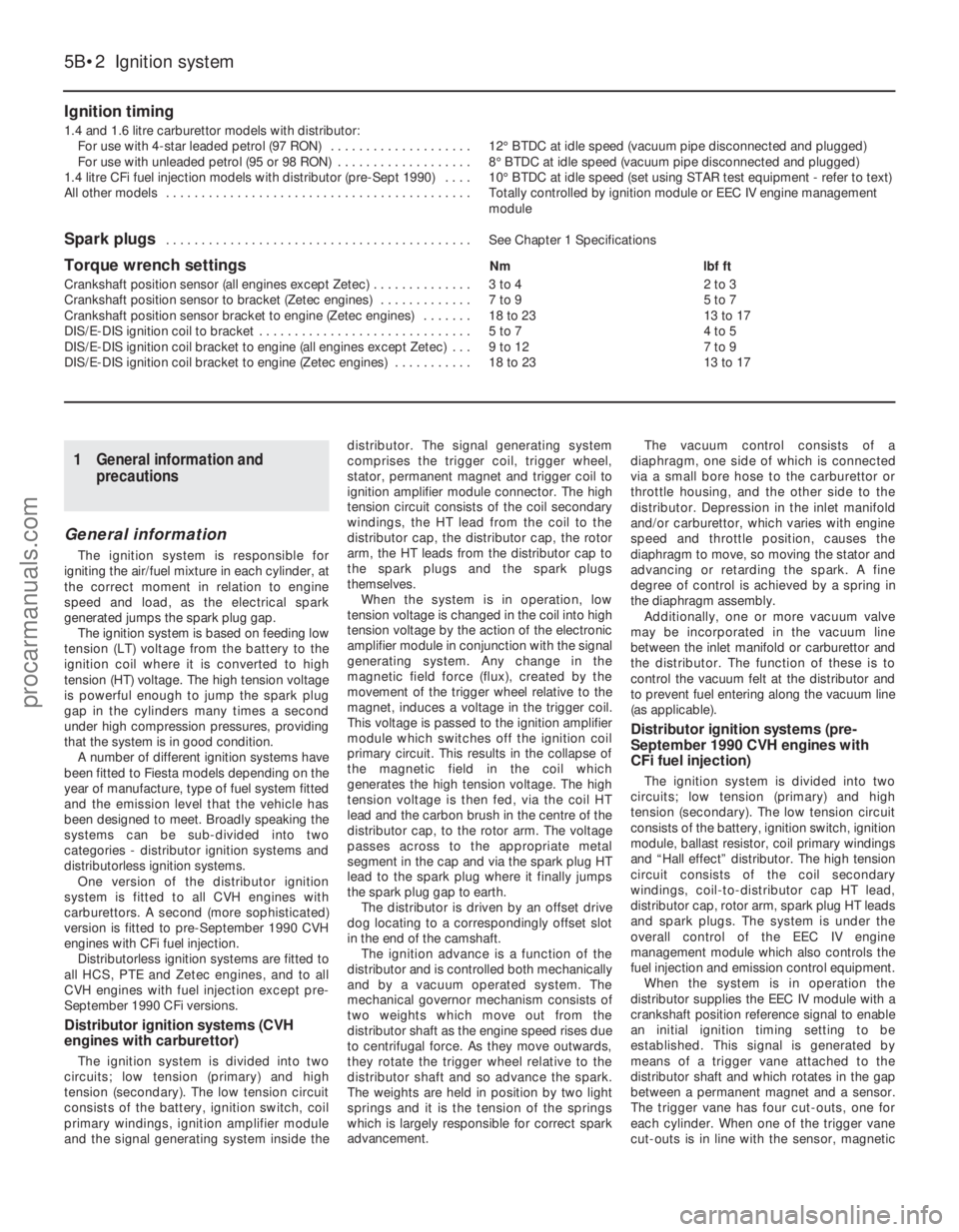
Ignition timing
1.4 and 1.6 litre carburettor models with distributor:For use with 4-star leaded petrol (97 RON) . . . . . . . . . . . . . . . . . . . . 12°BTDC at idle speed (vacuum pipe disconnected and plugged)
For use with unleaded petrol (95 or 98 RON) . . . . . . . . . . . . . . . . . . . 8° BTDC at idle speed (vacuum pipe disconnected and plugged)
1.4 litre CFi fuel injection models with distributor (pre-Sept 1990) . . . . 10°BTDC at idle speed (set using STAR test equipment - refer to text)
All other models . . . . . . . . . . . . . . . . . . . . . . . . . . . . . . . . . . . .\
. . . . . . . Totally controlled by ignition module or EEC IV engine management module
Spark plugs . . . . . . . . . . . . . . . . . . . . . . . . . . . . . . . . . . . .\
. . . . . . . See Chapter 1 Specifications
Torque wrench settingsNmlbf ft
Crankshaft position sensor (all engines except Zetec) . . . . . . . . . . . . . . 3 to 4 2 to 3
Crankshaft position sensor to bracket (Zetec engines) . . . . . . . . . . . . . 7 to 9 5 to 7
Crankshaft position sensor bracket to engine (Zetec engines) . . . . . . . 18 to 23 13 to 17
DIS/E-DIS ignition coil to bracket . . . . . . . . . . . . . . . . . . . . . . . . . . . . . . 5 to 7 4 to 5
DIS/E-DIS ignition coil bracket to engine (all engines except Zetec) . . . 9 to 12 7 to 9
DIS/E-DIS ignition coil bracket to engine (Zetec engines) . . . . . . . . . . . 18 to 23 13 to 17
5B•2 Ignition system
1595Ford Fiesta Remake
1 General information and
precautions
General information
The ignition system is responsible for
igniting the air/fuel mixture in each cylinder, at
the correct moment in relation to engine
speed and load, as the electrical spark
generated jumps the spark plug gap. The ignition system is based on feeding low
tension (LT) voltage from the battery to the
ignition coil where it is converted to high
tension (HT) voltage. The high tension voltage
is powerful enough to jump the spark plug
gap in the cylinders many times a second
under high compression pressures, providing
that the system is in good condition. A number of different ignition systems have
been fitted to Fiesta models depending on the
year of manufacture, type of fuel system fitted
and the emission level that the vehicle has
been designed to meet. Broadly speaking the
systems can be sub-divided into two
categories - distributor ignition systems and
distributorless ignition systems. One version of the distributor ignition
system is fitted to all CVH engines with
carburettors. A second (more sophisticated)
version is fitted to pre-September 1990 CVH
engines with CFi fuel injection. Distributorless ignition systems are fitted to
all HCS, PTE and Zetec engines, and to all
CVH engines with fuel injection except pre-
September 1990 CFi versions.
Distributor ignition systems (CVH
engines with carburettor)
The ignition system is divided into two
circuits; low tension (primary) and high
tension (secondary). The low tension circuit
consists of the battery, ignition switch, coil
primary windings, ignition amplifier module
and the signal generating system inside the distributor. The signal generating system
comprises the trigger coil, trigger wheel,
stator, permanent magnet and trigger coil to
ignition amplifier module connector. The high
tension circuit consists of the coil secondary
windings, the HT lead from the coil to the
distributor cap, the distributor cap, the rotor
arm, the HT leads from the distributor cap to
the spark plugs and the spark plugs
themselves.
When the system is in operation, low
tension voltage is changed in the coil into high
tension voltage by the action of the electronic
amplifier module in conjunction with the signal
generating system. Any change in the
magnetic field force (flux), created by the
movement of the trigger wheel relative to the
magnet, induces a voltage in the trigger coil.
This voltage is passed to the ignition amplifier
module which switches off the ignition coil
primary circuit. This results in the collapse of
the magnetic field in the coil which
generates the high tension voltage. The high
tension voltage is then fed, via the coil HT
lead and the carbon brush in the centre of the
distributor cap, to the rotor arm. The voltage
passes across to the appropriate metal
segment in the cap and via the spark plug HT
lead to the spark plug where it finally jumps
the spark plug gap to earth. The distributor is driven by an offset drive
dog locating to a correspondingly offset slot
in the end of the camshaft.
The ignition advance is a function of the
distributor and is controlled both mechanically
and by a vacuum operated system. The
mechanical governor mechanism consists of
two weights which move out from the
distributor shaft as the engine speed rises due
to centrifugal force. As they move outwards,
they rotate the trigger wheel relative to the
distributor shaft and so advance the spark.
The weights are held in position by two light
springs and it is the tension of the springs
which is largely responsible for correct spark
advancement. The vacuum control consists of a
diaphragm, one side of which is connected
via a small bore hose to the carburettor or
throttle housing, and the other side to the
distributor. Depression in the inlet manifold
and/or carburettor, which varies with engine
speed and throttle position, causes the
diaphragm to move, so moving the stator and
advancing or retarding the spark. A fine
degree of control is achieved by a spring in
the diaphragm assembly. Additionally, one or more vacuum valve
may be incorporated in the vacuum line
between the inlet manifold or carburettor and
the distributor. The function of these is to
control the vacuum felt at the distributor and
to prevent fuel entering along the vacuum line
(as applicable).
Distributor ignition systems (pre-
September 1990 CVH engines with
CFi fuel injection)
The ignition system is divided into two
circuits; low tension (primary) and high
tension (secondary). The low tension circuit
consists of the battery, ignition switch, ignition
module, ballast resistor, coil primary windings
and “Hall effect” distributor. The high tension
circuit consists of the coil secondary
windings, coil-to-distributor cap HT lead,
distributor cap, rotor arm, spark plug HT leads
and spark plugs. The system is under the
overall control of the EEC IV engine
management module which also controls the
fuel injection and emission control equipment. When the system is in operation the
distributor supplies the EEC IV module with a
crankshaft position reference signal to enable
an initial ignition timing setting to be
established. This signal is generated by
means of a trigger vane attached to the
distributor shaft and which rotates in the gap
between a permanent magnet and a sensor.
The trigger vane has four cut-outs, one for
each cylinder. When one of the trigger vane
cut-outs is in line with the sensor, magnetic
procarmanuals.com
http://vnx.su
Page 170 of 296
flux can pass between the magnet and the
sensor. When a trigger vane segment is in line
with the sensor, the magnetic flux is diverted
through the trigger vane, away from the
sensor. The sensor detects the change in
magnetic flux and sends an impulse to the
EEC IV module. Additional data is received
from the engine coolant temperature sensor,
manifold absolute pressure sensor, inlet air
temperature sensor, throttle position sensor
and vehicle speed sensor. Using this
information the EEC IV module calculates the
optimum ignition advance setting and
switches off the low tension circuit via the
ignition module. This results in the collapse of
the magnetic field in the coil which generates
the high tension voltage. The high tension
voltage is then fed, via the coil HT lead and
the carbon brush in the centre of the
distributor cap, to the rotor arm. The voltage
passes across to the appropriate metal
segment in the cap and via the spark plug HT
lead to the spark plug where it finally jumps
the spark plug gap to earth. It can be seen
that the ignition module functions basically as
a high current switch by controlling the low
tension supply to the ignition coil primary
windings.In the event of failure of a sensor, the
EEC IV module will substitute a preset value
for that input to allow the system to continue
to function. In the event of failure of the
EEC IV module, a “limited operation strategy”
(LOS) function allows the vehicle to be driven,
albeit at reduced power and efficiency. The
EEC IV module also has a “keep alive
memory” (KAM) function which stores idle and
drive values and codes which can be used to
indicate any system fault which may occur.
Distributorless ignition systems
The main ignition system components
include the ignition switch, the battery, the
crankshaft speed/position sensor, the ignition
module, the coil, the primary (low tension/LT)
and secondary (high tension/HT) wiring
circuits, and the spark plugs. The system used on carburettor models is
termed DIS (Distributorless Ignition System),
and on fuel injection models E-DIS, (Electronic
Distributorless Ignition System). The primary
difference between the two is that the DIS
system is an independent ignition control
system while the E-DIS system operates in
conjunction with the EEC IV engine
management module which also controls the
fuel injection and emission control systems.
With both systems, the main functions of
the distributor are replaced by a computerised
ignition module and a coil unit. The coil unit
combines a double-ended pair of coils - each
time a coil receives an ignition signal, two
sparks are produced, at each end of the
secondary windings. One spark goes to a
cylinder on compression stroke and the other
goes to the corresponding cylinder on its
exhaust stroke. The first will give the correct power stroke, but the second spark will have
no effect (a “wasted spark”), occurring as it
does during exhaust conditions.
The ignition signal is generated by a
crankshaft position sensor which scans a
series of 36 protrusions on the periphery of
the engine flywheel. The inductive head of the
crankshaft position sensor runs just above the
flywheel periphery and as the crankshaft
rotates, the sensor transmits a pulse to the
ignition module every time a protrusion
passes it. There is one missing protrusion in
the flywheel periphery at a point
corresponding to 90° BTDC. The ignition
module recognises the absence of a pulse
from the crankshaft position sensor at this
point to establish a reference mark for
crankshaft position. Similarly, the time interval
between absent pulses is used to determine
engine speed. On carburettor engines, the ignition module
receives signals provided by information
sensors which monitor various engine
functions (such as crankshaft position,
coolant temperature, inlet air temperature,
inlet manifold vacuum etc). This information
allows the ignition module to generate the
optimum ignition timing setting under all
operating conditions.
On fuel injection engines, the ignition
module operates in conjunction with the
EEC IV engine management module, and
together with the various additional
information sensors and emission control
components, provides total control of the fuel
and ignition systems to form a complete
engine management package. The information contained in this Chapter
concentrates on the ignition-related
components of the engine management
system. Information covering the fuel, exhaust
and emission control components can be
found in the applicable Parts of Chapter 4.
Precautions
When working on the ignition system, take
the following precautions:
a) Do not keep the ignition switch on for
more than 10 seconds if the engine will
not start.
b) If a separate tachometer is ever required
for servicing work, consult a dealer
service department before buying a
tachometer for use with this vehicle -
some tachometers may be incompatible
with these types of ignition systems - and
always connect it in accordance with the
equipment manufacturer’s instructions.
c) Never connect the ignition coil terminals to earth. This could result in damage to
the coil and/or the ignition module.
d) Do not disconnect the battery when the
engine is running.
e) Make sure that the ignition module is
properly earthed.
f) Refer to the warning at the beginning of the next Section concerning HT voltage.
2 Ignition system - testing
2
Warning: Voltages produced by
an electronic ignition system are
considerably higher than those
produced by conventional
ignition systems. Extreme care must be
taken when working on the system with
the ignition switched on. Persons with
surgically-implanted cardiac pacemaker
devices should keep well clear of the
ignition circuits, components and test
equipment.
Note: Refer to the precautions given in
Section 1 of Part A of this Chapter before
starting work. Always switch off the ignition
before disconnecting or connecting any
component and when using a multi-meter to
check resistances.
1 If the engine turns over but won’t start,
disconnect the (HT) lead from any spark plug,
and attach it to a calibrated tester (available at
most automotive accessory shops). Connect
the clip on the tester to a good earth - a bolt
or metal bracket on the engine. If you’re
unable to obtain a calibrated ignition tester,
have the check carried out by a Ford dealer
service department or similar. Any other form
of testing (such as jumping a spark from the
end of an HT lead to earth) is not
recommended, because of the risk of
personal injury, or of damage to the ignition
module.
2 Crank the engine, and watch the end of the
tester to see if bright blue, well-defined sparks
occur.
3 If sparks occur, sufficient voltage is
reaching the plug to fire it. Repeat the
check at the remaining plugs, to ensure
that all leads are sound and that the
coil is serviceable. However, the plugs
themselves may be fouled or faulty, so
remove and check them as described in
Chapter 1.
4 If no sparks or intermittent sparks occur,
the spark plug lead(s) may be defective. Also,
on distributor systems, there may be
problems with the rotor arm or distributor cap
- check all these components as described in
Chapter 1.
5 If there’s still no spark, check the coil’s
electrical connector (where applicable), to
make sure it’s clean and tight. Check for full
battery voltage to the coil at the connector’s
centre terminal. Check the coil itself (see
Section 3). Make any necessary repairs, then
repeat the check again.
6 The remainder of the system checks should
be left to a dealer service department
or other qualified repair facility, as there is a
chance that the ignition module may
be damaged if tests are not performed
properly.
Ignition system 5B•3
5B
1595Ford Fiesta Remakeprocarmanuals.com
http://vnx.su
Page 199 of 296
16Using a suitable punch, tap the outer
bearing outer race at diametrically-opposed
points and remove the bearing assembly from
the spindle carrier. Do not allow the bearing to
tilt during its withdrawal from the housing, or it
will jam and possibly damage the surface of
the bore. Any burrs left in a bearing bore will
prevent the new bearing from seating
correctly.
17 Turn the spindle carrier over and remove
the inner bearing assembly in the same way.
18 Thoroughly clean the bearing bore and
hub, then secure the spindle carrier in the vice
in an upright position.
19 Draw the new outer bearing assembly into
the spindle carrier using a length of metal tube
of diameter slightly less than the outer race.
Do not apply any pressure to the inner race.
Alternatively, a long threaded rod or bolt, a nut
and large flat washers may be used to draw
the bearing into position (see illustration 3.7).
Once the bearing has been installed, take care
not to dislodge the inner race and seal.
20 Using the same method as for the outer
bearing, draw in the new inner bearing
assembly from the other side of the spindle
carrier. Again, take care not to dislodge the
inner race and seal once the bearing is in
position.
21 Using the same tooling arrangement as
before, and with the metal tube or washers
contacting the inner bearing inner race, draw
the hub fully into the bearings. Alternatively, if
a press is available, support the hub face
down on the press bed and using a metal tube
in contact with the inner bearing inner race,
press the spindle carrier onto the hub.
22 Check that the hub spins freely in the
bearings, then refit the spindle carrier as
described in Section 2.4 Front suspension strut -
removal and refitting
3
Removal
1 Chock the rear wheels then jack up the
front of the car and support it on axle stands
(see “Jacking and Vehicle Support” ). Remove
the appropriate front roadwheel.
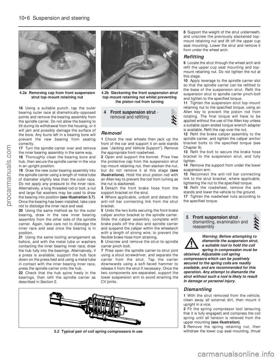
2 Open and support the bonnet. Prise free
the protective cap from the suspension strut
top-mount retaining nut, then slacken the nut,
but do not remove it at this stage (see
illustrations) . Hold the strut piston rod with
an Allen key to prevent the rod from turning as
the nut is slackened.
3 Detach the front brake hose from the
support bracket on the strut.
4 Where applicable, unbolt and detach the
anti-roll bar connecting link from the strut
bracket.
5 Undo the two bolts securing the front brake
caliper anchor bracket to the spindle carrier.
Slide the caliper assembly, complete with
brake pads off the disc and spindle carrier
and suspend the caliper within the wheelarch
with a length of strong wire, to prevent the
flexible brake hose from straining.
6 Unscrew and remove the strut-to-spindle
carrier pinch-bolt.
7 Prise open the spindle carrier-to-strut joint
using a stout screwdriver, and separate the
carrier from the strut. Tap the carrier
downwards using a soft-faced hammer to
release it from the strut if necessary. Once the
two components are separated, support the
lower suspension arm to avoid straining the
CV joints. 8
Support the weight of the strut underneath,
and unscrew the previously slackened top-
mount retaining nut and lift off the upper cup
seat mounting. Lower the strut and remove it
from under the wheel arch.
Refitting
9 Locate the strut through the wheel arch and
refit the upper cup seat mounting and top-
mount retaining nut. Do not tighten the nut at
this stage.
10 Apply leverage to the spindle carrier slot
so that the spindle carrier can be refitted to
the base of the suspension strut. Refit the
suspension strut to spindle carrier pinch-bolt
and tighten to the specified torque.
11 Tighten the suspension strut top-mount
retaining nut to the specified torque, using an
Allen key to prevent the piston rod from
rotating. The final torque will have to be
applied without the use of the Allen key unless
a suitable open-ended torque wrench adapter
is available. Refit the cap over the nut.
12 Refit the brake caliper assembly to the
spindle carrier, and tighten the caliper anchor
bracket bolts to the specified torque (see
Chapter 9).
13 Refit the bolt to secure the brake hose
bracket to the suspension strut, and fully
tighten.
14 Remove the support from under the lower
suspension arm.
15 Reconnect the anti-roll bar connecting
link to the strut bracket, where applicable,
tightening the nut to the specified torque.
16 Refit the roadwheel, remove the axle
stands and lower the vehicle to the ground.
17 Tighten the roadwheel nuts according to
the specified torque.
5 Front suspension strut -
dismantling, examination and
reassembly
4
Warning: Before attempting to
dismantle the suspension strut,
a suitable tool to hold the coil
spring in compression must be
obtained. Adjustable coil spring
compressors which can be positively
secured to the spring coils are readily
available, and are recommended for this
operation. Any attempt to dismantle the
strut without such a tool is likely to result
in damage or personal injury.
Dismantling
1 With the strut removed from the vehicle,
clean away all external dirt, then mount it
upright in a vice.
2 Fit the spring compressor tool (ensuring
that it is fully engaged) and compress the coil
spring until all tension is relieved from the
upper mounting (see illustration) .
3 Remove the spring retaining nut, then
withdraw the lower cup seat mounting, thrust
10•6 Suspension and steering
5.2 Typical pair of coil spring compressors in use
4.2b Slackening the front suspension strut
top-mount retaining nut whilst preventing the piston rod from turning4.2a Removing cap from front suspensionstrut top-mount retaining nut
1595Ford Fiesta Remakeprocarmanuals.com
http://vnx.su
Page 200 of 296
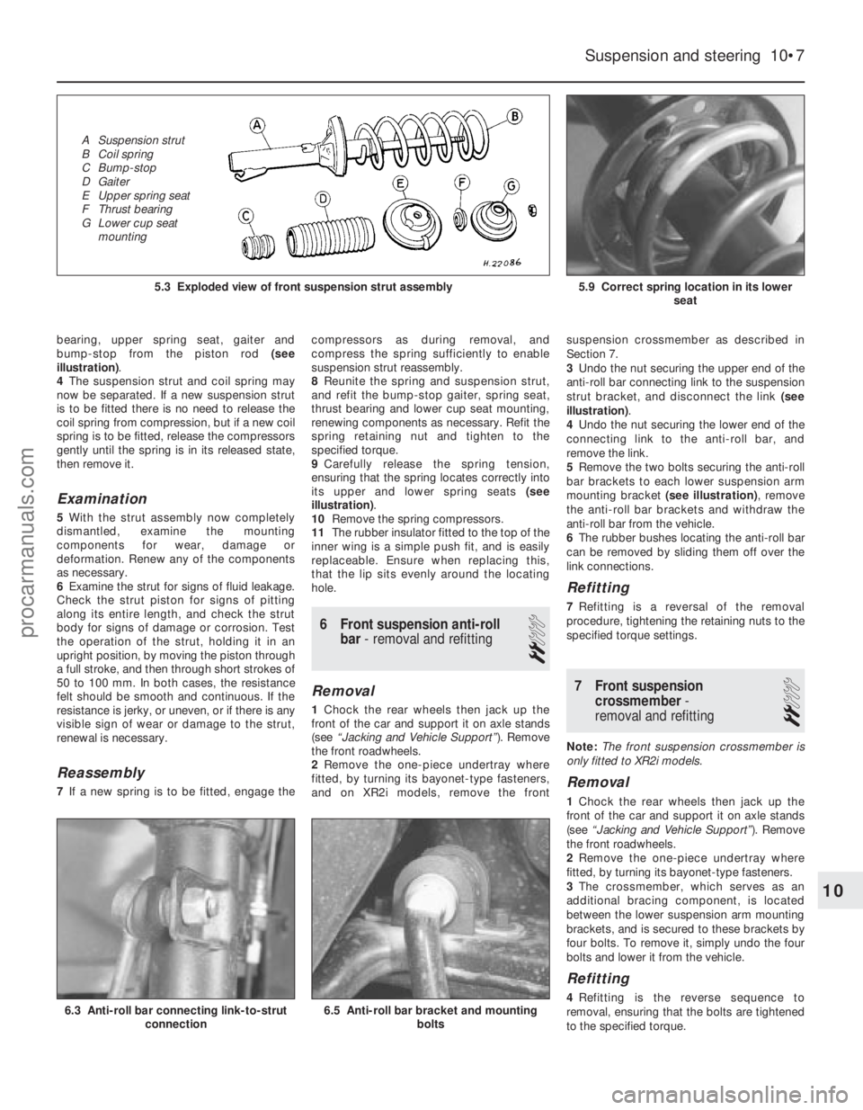
bearing, upper spring seat, gaiter and
bump-stop from the piston rod (see
illustration) .
4 The suspension strut and coil spring may
now be separated. If a new suspension strut
is to be fitted there is no need to release the
coil spring from compression, but if a new coil
spring is to be fitted, release the compressors
gently until the spring is in its released state,
then remove it.
Examination
5 With the strut assembly now completely
dismantled, examine the mounting
components for wear, damage or
deformation. Renew any of the components
as necessary.
6 Examine the strut for signs of fluid leakage.
Check the strut piston for signs of pitting
along its entire length, and check the strut
body for signs of damage or corrosion. Test
the operation of the strut, holding it in an
upright position, by moving the piston through
a full stroke, and then through short strokes of
50 to 100 mm. In both cases, the resistance
felt should be smooth and continuous. If the
resistance is jerky, or uneven, or if there is any
visible sign of wear or damage to the strut,
renewal is necessary.
Reassembly
7 If a new spring is to be fitted, engage the compressors as during removal, and
compress the spring sufficiently to enable
suspension strut reassembly.
8
Reunite the spring and suspension strut,
and refit the bump-stop gaiter, spring seat,
thrust bearing and lower cup seat mounting,
renewing components as necessary. Refit the
spring retaining nut and tighten to the
specified torque.
9 Carefully release the spring tension,
ensuring that the spring locates correctly into
its upper and lower spring seats (see
illustration) .
10 Remove the spring compressors.
11 The rubber insulator fitted to the top of the
inner wing is a simple push fit, and is easily
replaceable. Ensure when replacing this,
that the lip sits evenly around the locating
hole.
6 Front suspension anti-roll
bar - removal and refitting
2
Removal
1Chock the rear wheels then jack up the
front of the car and support it on axle stands
(see “Jacking and Vehicle Support” ). Remove
the front roadwheels.
2 Remove the one-piece undertray where
fitted, by turning its bayonet-type fasteners,
and on XR2i models, remove the front suspension crossmember as described in
Section 7.
3
Undo the nut securing the upper end of the
anti-roll bar connecting link to the suspension
strut bracket, and disconnect the link (see
illustration) .
4 Undo the nut securing the lower end of the
connecting link to the anti-roll bar, and
remove the link.
5 Remove the two bolts securing the anti-roll
bar brackets to each lower suspension arm
mounting bracket (see illustration), remove
the anti-roll bar brackets and withdraw the
anti-roll bar from the vehicle.
6 The rubber bushes locating the anti-roll bar
can be removed by sliding them off over the
link connections.
Refitting
7 Refitting is a reversal of the removal
procedure, tightening the retaining nuts to the
specified torque settings.
7 Front suspension crossmember -
removal and refitting
2
Note: The front suspension crossmember is
only fitted to XR2i models.
Removal
1 Chock the rear wheels then jack up the
front of the car and support it on axle stands
(see “Jacking and Vehicle Support” ). Remove
the front roadwheels.
2 Remove the one-piece undertray where
fitted, by turning its bayonet-type fasteners.
3 The crossmember, which serves as an
additional bracing component, is located
between the lower suspension arm mounting
brackets, and is secured to these brackets by
four bolts. To remove it, simply undo the four
bolts and lower it from the vehicle.
Refitting
4 Refitting is the reverse sequence to
removal, ensuring that the bolts are tightened
to the specified torque.
Suspension and steering 10•7
5.9 Correct spring location in its lower seat5.3 Exploded view of front suspension strut assembly
6.5 Anti-roll bar bracket and mountingbolts6.3 Anti-roll bar connecting link-to-strutconnection
10
1595Ford Fiesta Remake
A Suspension strut
B Coil spring
C Bump-stop
D Gaiter
E Upper spring seat
F Thrust bearing
G Lower cup seat
mountingprocarmanuals.com
http://vnx.su
Page 202 of 296
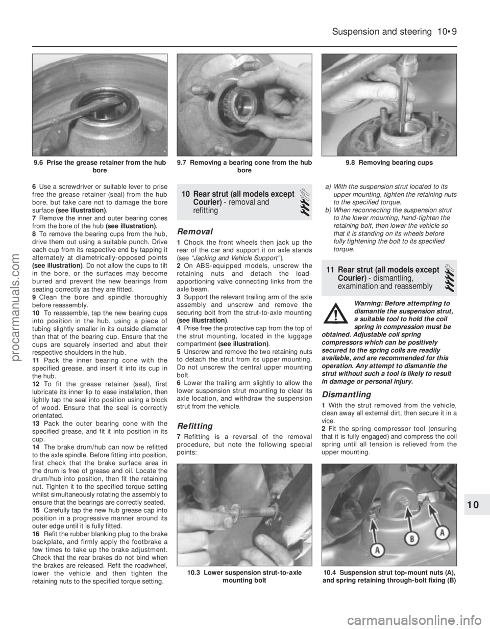
6Use a screwdriver or suitable lever to prise
free the grease retainer (seal) from the hub
bore, but take care not to damage the bore
surface (see illustration) .
7 Remove the inner and outer bearing cones
from the bore of the hub (see illustration).
8 To remove the bearing cups from the hub,
drive them out using a suitable punch. Drive
each cup from its respective end by tapping it
alternately at diametrically-opposed points
(see illustration) . Do not allow the cups to tilt
in the bore, or the surfaces may become
burred and prevent the new bearings from
seating correctly as they are fitted.
9 Clean the bore and spindle thoroughly
before reassembly.
10 To reassemble, tap the new bearing cups
into position in the hub, using a piece of
tubing slightly smaller in its outside diameter
than that of the bearing cup. Ensure that the
cups are squarely inserted and abut their
respective shoulders in the hub.
11 Pack the inner bearing cone with the
specified grease, and insert it into its cup in
the hub.
12 To fit the grease retainer (seal), first
lubricate its inner lip to ease installation, then
lightly tap the seal into position using a block
of wood. Ensure that the seal is correctly
orientated.
13 Pack the outer bearing cone with the
specified grease, and fit it into position in its
cup.
14 The brake drum/hub can now be refitted
to the axle spindle. Before fitting into position,
first check that the brake surface area in
the drum is free of grease and oil. Locate the
drum/hub into position, then fit the retaining
nut. Tighten it to the specified torque setting
whilst simultaneously rotating the assembly to
ensure that the bearings are correctly seated.
15 Carefully tap the new hub grease cap into
position in a progressive manner around its
outer edge until it is fully fitted.
16 Refit the rubber blanking plug to the brake
backplate, and firmly apply the footbrake a
few times to take up the brake adjustment.
Check that the rear brakes do not bind when
the brakes are released. Refit the roadwheel,
lower the vehicle and then tighten the
retaining nuts to the specified torque setting.10 Rear strut (all models except Courier) - removal and
refitting
3
Removal
1 Chock the front wheels then jack up the
rear of the car and support it on axle stands
(see “Jacking and Vehicle Support” ).
2 On ABS-equipped models, unscrew the
retaining nuts and detach the load-
apportioning valve connecting links from the
axle beam.
3 Support the relevant trailing arm of the axle
assembly and unscrew and remove the
securing bolt from the strut-to-axle mounting
(see illustration) .
4 Prise free the protective cap from the top of
the strut mounting, located in the luggage
compartment (see illustration) .
5 Unscrew and remove the two retaining nuts
to detach the strut from its upper mounting.
Do not unscrew the central upper mounting
bolt.
6 Lower the trailing arm slightly to allow the
lower suspension strut mounting to clear its
axle location, and withdraw the suspension
strut from the vehicle.
Refitting
7 Refitting is a reversal of the removal
procedure, but note the following special
points: a)
With the suspension strut located to its
upper mounting, tighten the retaining nuts
to the specified torque.
b) When reconnecting the suspension strut
to the lower mounting, hand-tighten the
retaining bolt, then lower the vehicle so
that it is standing on its wheels before
fully tightening the bolt to its specified
torque.
11 Rear strut (all models except
Courier) - dismantling,
examination and reassembly
4
Warning: Before attempting to
dismantle the suspension strut,
a suitable tool to hold the coil
spring in compression must be
obtained. Adjustable coil spring
compressors which can be positively
secured to the spring coils are readily
available, and are recommended for this
operation. Any attempt to dismantle the
strut without such a tool is likely to result
in damage or personal injury.
Dismantling
1 With the strut removed from the vehicle,
clean away all external dirt, then secure it in a
vice.
2 Fit the spring compressor tool (ensuring
that it is fully engaged) and compress the coil
spring until all tension is relieved from the
upper mounting.
Suspension and steering 10•9
9.8 Removing bearing cups9.7 Removing a bearing cone from the hub bore9.6 Prise the grease retainer from the hubbore
10.4 Suspension strut top-mount nuts (A),
and spring retaining through-bolt fixing (B)10.3 Lower suspension strut-to-axle mounting bolt
10
1595Ford Fiesta Remakeprocarmanuals.com
http://vnx.su
Page 203 of 296
3Unscrew and remove the upper mounting
through-bolt and nut.
4 Withdraw the upper mounting cup and the
spring seat.
5 The suspension strut and coil spring can now
be separated. If the coil spring or strut is to be
renewed, the original coil spring must be
released from the compressor. If it is to be re-
used, the coil spring can be left in compression.
Examination
6 With the strut assembly now completely
dismantled, examine the mounting
components for wear, damage or deformation.
Renew any of the components as necessary.
7 Examine the strut for signs of fluid leakage.
Check the strut piston for signs of pitting
along its entire length, and check the strut
body for signs of damage or deterioration of
the mountings. Test the operation of the strut,
holding it in an upright position, by moving the
piston through a full stroke, and then through
short strokes of 50 to 100 mm. In both cases,
the resistance felt should be smooth and
continuous. If the resistance is jerky, or
uneven, or if there is any visible sign of wear
or damage to the strut, renewal is necessary.
Reassembly
8 Reassembly is a reversal of the dismantling
procedure but note the following points: a) When the spring is located over the
suspension strut, the spring seat, cup and
through-bolt fitted, tighten the retaining
bolt to the specified torque.
b) When reassembled, check that the upper
and lower spring tails are correctly
engaged with their spring seats before
removing the spring compressor.
12 Rear axle (all models except
Courier) -
removal and refitting
3
Removal
1 Chock the front wheels then jack up the
rear of the car and support it on axle stands
(see “Jacking and Vehicle Support” ). Remove
the rear roadwheels.
2 Refer to Chapter 9 for details, and disconnect
the handbrake cable equaliser from the primary
cable. Remove the handbrake rear cable from
its adjuster and its fixed body locations.
3 Disconnect the rear brake flexible hydraulic
brake hoses from their rigid line connections.
Clamp the hoses before disconnecting them,
to minimise the fluid loss and air entry into the
hydraulic system (see Chapter 9 for details).
4 On ABS-equipped models, undo the
retaining nuts and detach the ABS load-
apportioning valve operating links from the
axle beam. Do not remove the load-
apportioning valve (see Chapter 9).
5 Locate suitable jacks or axle stands under
the axle beam to support its weight (not to lift
it), then unscrew the four mounting bracket
bolts each side. 6
Unscrew and remove the strut-to-axle
mounting bolt each side.
7 Check that all associated fittings are clear,
then lower the axle and remove it from under
the vehicle.
8 If the twist beam axle has been damaged, it
must be renewed. Refer to Chapter 9 for
details on removing the rear brakes from the
axle. To remove the front mounting/pivot
brackets from the axle, unscrew the pivot bolt.
Refitting
9 Refitting is a reversal of the removal
procedure, but note the following: a) Reconnect the axle at the front floor mountings first, and tighten the retaining
bolts to the specified torque.
b) Reconnect the axle to the suspension struts, but do not fully retighten the securing
bolts until after the vehicle is lowered to the
ground and is standing on its wheels.
c) Ensure that all brake fluid line connections are clean before reconnecting them. Refer
to the appropriate Sections in Chapter 9
for specific details on reconnecting the
brake lines, bleeding the brake hydraulic
system, and for reconnecting the
handbrake cable and its adjustment.
d) When the vehicle is lowered and is standing
on its wheels, tighten the suspension
fastenings to their specified torque settings.
13 Rear axle pivot bushes (all
models except Courier) -
renewal
3
Note: Two different types of pivot bushes
have been fitted during the course of Fiesta
production. It is understood that once stocks
of the early type are exhausted, only the latter
type will be supplied by Ford parts dealers. If
renewing pivot bushes on a pre-April 1990
model, and only the later type bushes are
available, fit the new bushes as described
from paragraph 15 onward.
Pre-April 1990 models
1 Chock the front wheels then jack up the
rear of the car and support it on axle stands
(see “Jacking and Vehicle Support” ).2
Position a suitable support (preferably
adjustable) under the axle twist beam so that
it is capable of carrying the weight of the axle
(not the weight of the vehicle).
3 On ABS-equipped models, undo the
retaining nuts and detach the ABS load-
apportioning valve operating links from the
axle beam. Do not remove the load-
apportioning valve (see Chapter 9).
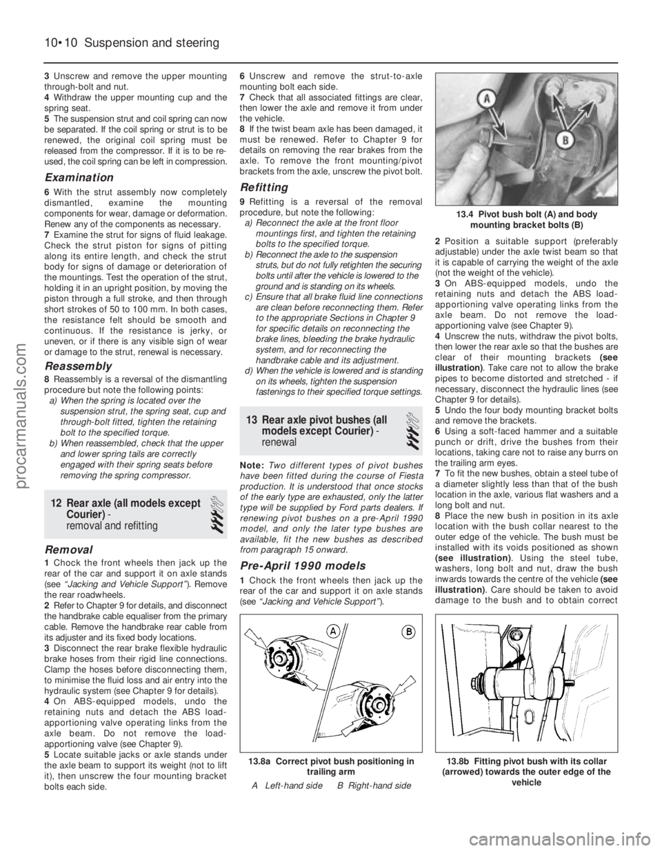
4 Unscrew the nuts, withdraw the pivot bolts,
then lower the rear axle so that the bushes are
clear of their mounting brackets (see
illustration) . Take care not to allow the brake
pipes to become distorted and stretched - if
necessary, disconnect the hydraulic lines (see
Chapter 9 for details).
5 Undo the four body mounting bracket bolts
and remove the brackets.
6 Using a soft-faced hammer and a suitable
punch or drift, drive the bushes from their
locations, taking care not to raise any burrs on
the trailing arm eyes.
7 To fit the new bushes, obtain a steel tube of
a diameter slightly less than that of the bush
location in the axle, various flat washers and a
long bolt and nut.
8 Place the new bush in position in its axle
location with the bush collar nearest to the
outer edge of the vehicle. The bush must be
installed with its voids positioned as shown
(see illustration) . Using the steel tube,
washers, long bolt and nut, draw the bush
inwards towards the centre of the vehicle (see
illustration) . Care should be taken to avoid
damage to the bush and to obtain correct
10•10 Suspension and steering
13.8b Fitting pivot bush with its collar
(arrowed) towards the outer edge of the vehicle13.8a Correct pivot bush positioning intrailing arm
A Left-hand side B Right-hand side
13.4 Pivot bush bolt (A) and body mounting bracket bolts (B)
1595Ford Fiesta Remakeprocarmanuals.com
http://vnx.su
Page 275 of 296
MImpact screwdriver
M Micrometer and/or vernier calipers (see
illustrations)
M Dial gauge (see illustration)
M Universal electrical multi-meter
M Cylinder compression gauge
(see illustration)
M Clutch plate alignment set (see
illustration)
M Brake shoe steady spring cup removal tool
(see illustration)
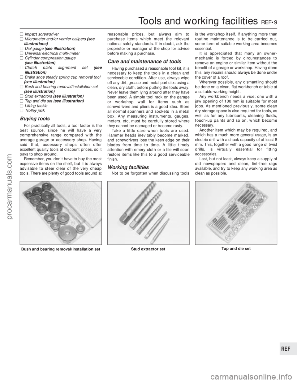
M Bush and bearing removal/installation set
(see illustration)
M Stud extractors (see illustration)
M Tap and die set (see illustration)
M Lifting tackle
M Trolley jack
Buying tools
For practically all tools, a tool factor is the
best source, since he will have a very
comprehensive range compared with the
average garage or accessory shop. Having
said that, accessory shops often offer
excellent quality tools at discount prices, so it
pays to shop around. Remember, you don’t have to buy the most
expensive items on the shelf, but it is always
advisable to steer clear of the very cheap
tools. There are plenty of good tools around at reasonable prices, but always aim to
purchase items which meet the relevant
national safety standards. If in doubt, ask the
proprietor or manager of the shop for advice
before making a purchase.
Care and maintenance of tools
Having purchased a reasonable tool kit, it is
necessary to keep the tools in a clean and
serviceable condition. After use, always wipe
off any dirt, grease and metal particles using a
clean, dry cloth, before putting the tools away.
Never leave them lying around after they have
been used. A simple tool rack on the garage
or workshop wall for items such as
screwdrivers and pliers is a good idea. Store
all normal spanners and sockets in a metal
box. Any measuring instruments, gauges,
meters, etc, must be carefully stored where
they cannot be damaged or become rusty. Take a little care when tools are used.
Hammer heads inevitably become marked,
and screwdrivers lose the keen edge on their
blades from time to time. A little timely
attention with emery cloth or a file will soon
restore items like this to a good serviceable
finish.
Working facilities
Not to be forgotten when discussing tools is the workshop itself. If anything more than
routine maintenance is to be carried out,
some form of suitable working area becomes
essential.
It is appreciated that many an owner-
mechanic is forced by circumstances to
remove an engine or similar item without the
benefit of a garage or workshop. Having done
this, any repairs should always be done under
the cover of a roof. Wherever possible, any dismantling should
be done on a clean, flat workbench or table at
a suitable working height. Any workbench needs a vice; one with a
jaw opening of 100 mm is suitable for most
jobs. As mentioned previously, some clean
dry storage space is also required for tools, as
well as for any lubricants, cleaning fluids,
touch-up paints and so on, which become
necessary.
Another item which may be required, and
which has a much more general usage, is an
electric drill with a chuck capacity of at least 8
mm. This, together with a good range of twist
drills, is virtually essential for fitting
accessories.
Last, but not least, always keep a supply of
old newspapers and clean, lint-free rags
available, and try to keep any working area as
clean as possible.
Bush and bearing removal/installation set Stud extractor setTap and die set
1595 Ford Fiesta Remake
Tools and working facilitiesREF•9
REF
procarmanuals.com
http://vnx.su