1989 FORD FIESTA fuel pressure
[x] Cancel search: fuel pressurePage 30 of 296
connecting rods (after removing the cylinder
head and sump) without removing the engine.
However, this is not recommended. Work of
this nature is more easily and thoroughly
completed with the engine on the bench, as
described in Chapter 2D.
2 Compression test-
description and interpretation
2
1 When engine performance is down, or if
misfiring occurs which cannot be attributed to
the ignition or fuel systems, a compression
test can provide diagnostic clues as to the
engine’s condition. If the test is performed
regularly, it can give warning of trouble before
any other symptoms become apparent.
2 The engine must be fully warmed-up to
normal operating temperature, the oil level
must be correct and the battery must be fully
charged. The aid of an assistant will also be
required.
3 On fuel injection engines, refer to Chap-
ter 12 and remove the fuel pump fuse from the
fusebox. Now start the engine and allow it to
run until it stalls.
4 Disable the ignition system by
disconnecting the multi-plug from the DIS or
E-DIS ignition coil. Remove all the spark plugs
with reference to Chapter 1 if necessary.
5 Fit a compression tester to the No 1
cylinder spark plug hole - the type of tester
which screws into the plug thread is to be
preferred.
6 Arrange for an assistant to hold the
accelerator pedal fully depressed to the floor,
while at the same time cranking the engine
over for several seconds on the starter motor.
Observe the compression gauge reading. The
compression will build up fairly quickly in a
healthy engine. Low compression on the first
stroke, followed by gradually-increasing
pressure on successive strokes, indicates
worn piston rings. A low compression on the
first stroke which does not rise on successive
strokes, indicates leaking valves or a blown
head gasket (a cracked cylinder head could
also be the cause). Deposits on the underside
of the valve heads can also cause low
compression. Record the highest gauge
reading obtained, then repeat the procedure
for the remaining cylinders.
7 Due to the variety of testers available, and
the fluctuation in starter motor speed when
cranking the engine, different readings
are often obtained when carrying out
the compression test. For this reason, actual
compression pressure figures are not quoted
by Ford. However, the most important factor
is that the compression pressures are uniform
in all cylinders, and that is what this test is
mainly concerned with.
8 Add some engine oil (about three squirts
from a plunger type oil can) to each cylinder
through the spark plug holes, and then repeat
the test. 9
If the compression increases after the oil is
added, it is indicative that the piston rings are
definitely worn. If the compression does not
increase significantly, the leakage is occurring
at the valves or the head gasket. Leakage
past the valves may be caused by burned
valve seats and/or faces, or warped, cracked
or bent valves.
10 If two adjacent cylinders have equally low
compressions, it is most likely that the head
gasket has blown between them. The
appearance of coolant in the combustion
chambers or on the engine oil dipstick would
verify this condition.
11 If one cylinder is about 20 percent lower
than the other, and the engine has a slightly
rough idle, a worn lobe on the camshaft could
be the cause.
12 On completion of the checks, refit the
spark plugs and reconnect the HT leads and
the ignition coil plug. Refit the fuel pump fuse
to the fusebox.
3 Top Dead Centre (TDC) for No 1 piston - locating
2
1Top dead centre (TDC) is the highest point
of the cylinder that each piston reaches as the
crankshaft turns. Each piston reaches its TDC
position at the end of its compression stroke,
and then again at the end of its exhaust
stroke. For the purpose of engine timing, TDC
at the end of the compression stroke for No 1
piston is used. On the HCS engine, No 1
cylinder is at the crankshaft pulley/timing
chain end of the engine. Proceed as follows.
2 Ensure that the ignition is switched off.
Disconnect the HT leads from the spark plugs,
then unscrew and remove the plugs as
described in Chapter 1.
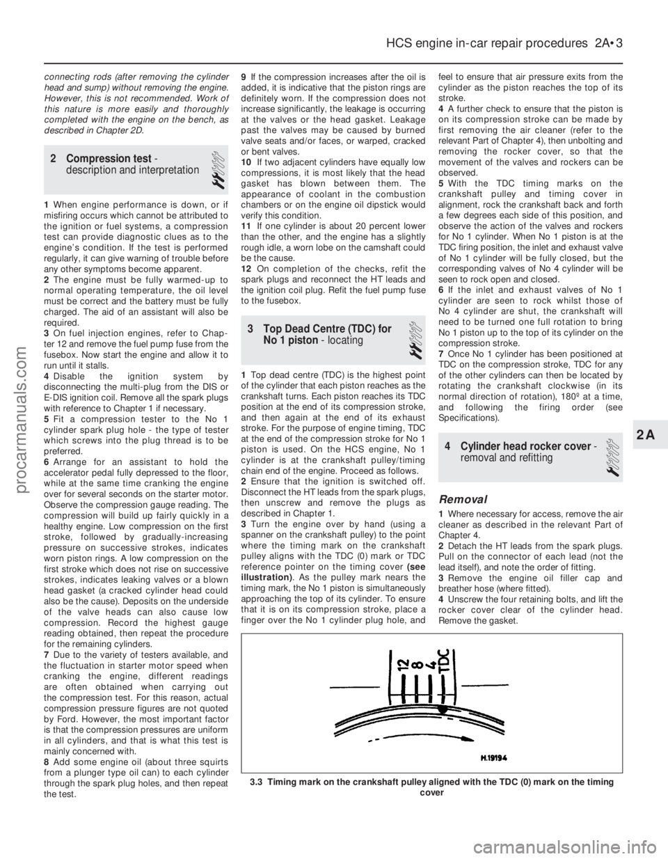
3 Turn the engine over by hand (using a
spanner on the crankshaft pulley) to the point
where the timing mark on the crankshaft
pulley aligns with the TDC (0) mark or TDC
reference pointer on the timing cover (see
illustration) . As the pulley mark nears the
timing mark, the No 1 piston is simultaneously
approaching the top of its cylinder. To ensure
that it is on its compression stroke, place a
finger over the No 1 cylinder plug hole, and feel to ensure that air pressure exits from the
cylinder as the piston reaches the top of its
stroke.
4
A further check to ensure that the piston is
on its compression stroke can be made by
first removing the air cleaner (refer to the
relevant Part of Chapter 4), then unbolting and
removing the rocker cover, so that the
movement of the valves and rockers can be
observed.
5 With the TDC timing marks on the
crankshaft pulley and timing cover in
alignment, rock the crankshaft back and forth
a few degrees each side of this position, and
observe the action of the valves and rockers
for No 1 cylinder. When No 1 piston is at the
TDC firing position, the inlet and exhaust valve
of No 1 cylinder will be fully closed, but the
corresponding valves of No 4 cylinder will be
seen to rock open and closed.
6 If the inlet and exhaust valves of No 1
cylinder are seen to rock whilst those of
No 4 cylinder are shut, the crankshaft will
need to be turned one full rotation to bring
No 1 piston up to the top of its cylinder on the
compression stroke.
7 Once No 1 cylinder has been positioned at
TDC on the compression stroke, TDC for any
of the other cylinders can then be located by
rotating the crankshaft clockwise (in its
normal direction of rotation), 180º at a time,
and following the firing order (see
Specifications).
4 Cylinder head rocker cover -
removal and refitting
1
Removal
1 Where necessary for access, remove the air
cleaner as described in the relevant Part of
Chapter 4.
2 Detach the HT leads from the spark plugs.
Pull on the connector of each lead (not the
lead itself), and note the order of fitting.
3 Remove the engine oil filler cap and
breather hose (where fitted).
4 Unscrew the four retaining bolts, and lift the
rocker cover clear of the cylinder head.
Remove the gasket.
HCS engine in-car repair procedures 2A•3
3.3 Timing mark on the crankshaft pulley aligned with the TDC (0) mar\
k on the timing cover
2A
1595Ford Fiesta Remakeprocarmanuals.com
http://vnx.su
Page 32 of 296
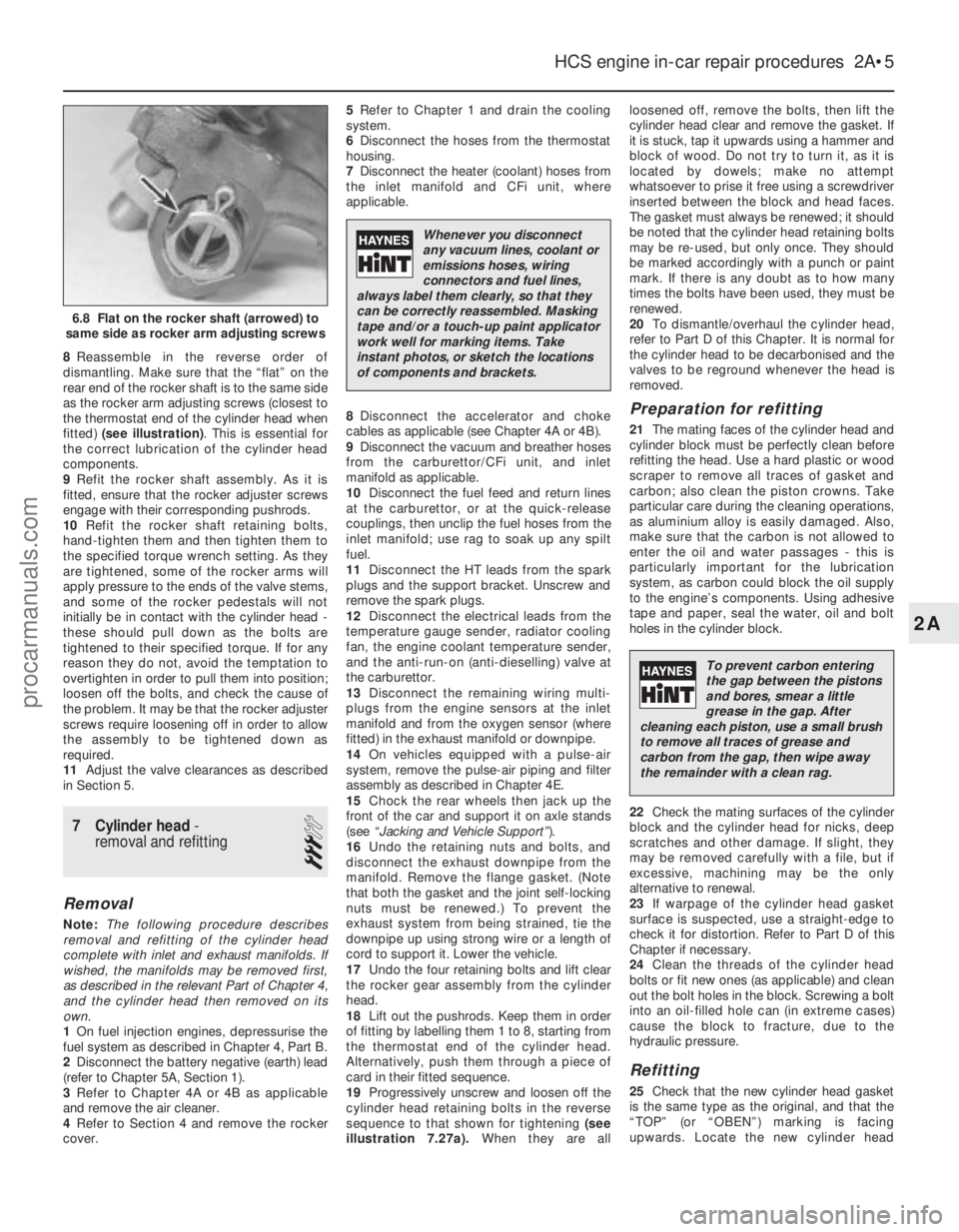
8Reassemble in the reverse order of
dismantling. Make sure that the “flat” on the
rear end of the rocker shaft is to the same side
as the rocker arm adjusting screws (closest to
the thermostat end of the cylinder head when
fitted) (see illustration) . This is essential for
the correct lubrication of the cylinder head
components.
9 Refit the rocker shaft assembly. As it is
fitted, ensure that the rocker adjuster screws
engage with their corresponding pushrods.
10 Refit the rocker shaft retaining bolts,
hand-tighten them and then tighten them to
the specified torque wrench setting. As they
are tightened, some of the rocker arms will
apply pressure to the ends of the valve stems,
and some of the rocker pedestals will not
initially be in contact with the cylinder head -
these should pull down as the bolts are
tightened to their specified torque. If for any
reason they do not, avoid the temptation to
overtighten in order to pull them into position;
loosen off the bolts, and check the cause of
the problem. It may be that the rocker adjuster
screws require loosening off in order to allow
the assembly to be tightened down as
required.
11 Adjust the valve clearances as described
in Section 5.
7 Cylinder head -
removal and refitting
3
Removal
Note: The following procedure describes
removal and refitting of the cylinder head
complete with inlet and exhaust manifolds. If
wished, the manifolds may be removed first,
as described in the relevant Part of Chapter 4,
and the cylinder head then removed on its
own.
1 On fuel injection engines, depressurise the
fuel system as described in Chapter 4, Part B.
2 Disconnect the battery negative (earth) lead
(refer to Chapter 5A, Section 1).
3 Refer to Chapter 4A or 4B as applicable
and remove the air cleaner.
4 Refer to Section 4 and remove the rocker
cover. 5
Refer to Chapter 1 and drain the cooling
system.
6 Disconnect the hoses from the thermostat
housing.
7 Disconnect the heater (coolant) hoses from
the inlet manifold and CFi unit, where
applicable.
8 Disconnect the accelerator and choke
cables as applicable (see Chapter 4A or 4B).
9 Disconnect the vacuum and breather hoses
from the carburettor/CFi unit, and inlet
manifold as applicable.
10 Disconnect the fuel feed and return lines
at the carburettor, or at the quick-release
couplings, then unclip the fuel hoses from the
inlet manifold; use rag to soak up any spilt
fuel.
11 Disconnect the HT leads from the spark
plugs and the support bracket. Unscrew and
remove the spark plugs.
12 Disconnect the electrical leads from the
temperature gauge sender, radiator cooling
fan, the engine coolant temperature sender,
and the anti-run-on (anti-dieselling) valve at
the carburettor.
13 Disconnect the remaining wiring multi-
plugs from the engine sensors at the inlet
manifold and from the oxygen sensor (where
fitted) in the exhaust manifold or downpipe.
14 On vehicles equipped with a pulse-air
system, remove the pulse-air piping and filter
assembly as described in Chapter 4E.
15 Chock the rear wheels then jack up the
front of the car and support it on axle stands
(see “Jacking and Vehicle Support” ).
16 Undo the retaining nuts and bolts, and
disconnect the exhaust downpipe from the
manifold. Remove the flange gasket. (Note
that both the gasket and the joint self-locking
nuts must be renewed.) To prevent the
exhaust system from being strained, tie the
downpipe up using strong wire or a length of
cord to support it. Lower the vehicle.
17 Undo the four retaining bolts and lift clear
the rocker gear assembly from the cylinder
head.
18 Lift out the pushrods. Keep them in order
of fitting by labelling them 1 to 8, starting from
the thermostat end of the cylinder head.
Alternatively, push them through a piece of
card in their fitted sequence.
19 Progressively unscrew and loosen off the
cylinder head retaining bolts in the reverse
sequence to that shown for tightening (see
illustration 7.27a). When they are all loosened off, remove the bolts, then lift the
cylinder head clear and remove the gasket. If
it is stuck, tap it upwards using a hammer and
block of wood. Do not try to turn it, as it is
located by dowels; make no attempt
whatsoever to prise it free using a screwdriver
inserted between the block and head faces.
The gasket must always be renewed; it should
be noted that the cylinder head retaining bolts
may be re-used, but only once. They should
be marked accordingly with a punch or paint
mark. If there is any doubt as to how many
times the bolts have been used, they must be
renewed.
20
To dismantle/overhaul the cylinder head,
refer to Part D of this Chapter. It is normal for
the cylinder head to be decarbonised and the
valves to be reground whenever the head is
removed.
Preparation for refitting
21 The mating faces of the cylinder head and
cylinder block must be perfectly clean before
refitting the head. Use a hard plastic or wood
scraper to remove all traces of gasket and
carbon; also clean the piston crowns. Take
particular care during the cleaning operations,
as aluminium alloy is easily damaged. Also,
make sure that the carbon is not allowed to
enter the oil and water passages - this is
particularly important for the lubrication
system, as carbon could block the oil supply
to the engine’s components. Using adhesive
tape and paper, seal the water, oil and bolt
holes in the cylinder block.
22 Check the mating surfaces of the cylinder
block and the cylinder head for nicks, deep
scratches and other damage. If slight, they
may be removed carefully with a file, but if
excessive, machining may be the only
alternative to renewal.
23 If warpage of the cylinder head gasket
surface is suspected, use a straight-edge to
check it for distortion. Refer to Part D of this
Chapter if necessary.
24 Clean the threads of the cylinder head
bolts or fit new ones (as applicable) and clean
out the bolt holes in the block. Screwing a bolt
into an oil-filled hole can (in extreme cases)
cause the block to fracture, due to the
hydraulic pressure.
Refitting
25 Check that the new cylinder head gasket
is the same type as the original, and that the
“TOP” (or “OBEN”) marking is facing
upwards. Locate the new cylinder head
HCS engine in-car repair procedures 2A•5
6.8 Flat on the rocker shaft (arrowed) to
same side as rocker arm adjusting screws
2A
1595Ford Fiesta Remake
Whenever you disconnect
any vacuum lines, coolant or
emissions hoses, wiring
connectors and fuel lines,
always label them clearly, so that they
can be correctly reassembled. Masking
tape and/or a touch-up paint applicator
work well for marking items. Take
instant photos, or sketch the locations
of components and brackets.
To prevent carbon entering
the gap between the pistons
and bores, smear a little
grease in the gap. After
cleaning each piston, use a small brush
to remove all traces of grease and
carbon from the gap, then wipe away
the remainder with a clean rag.
procarmanuals.com
http://vnx.su
Page 33 of 296
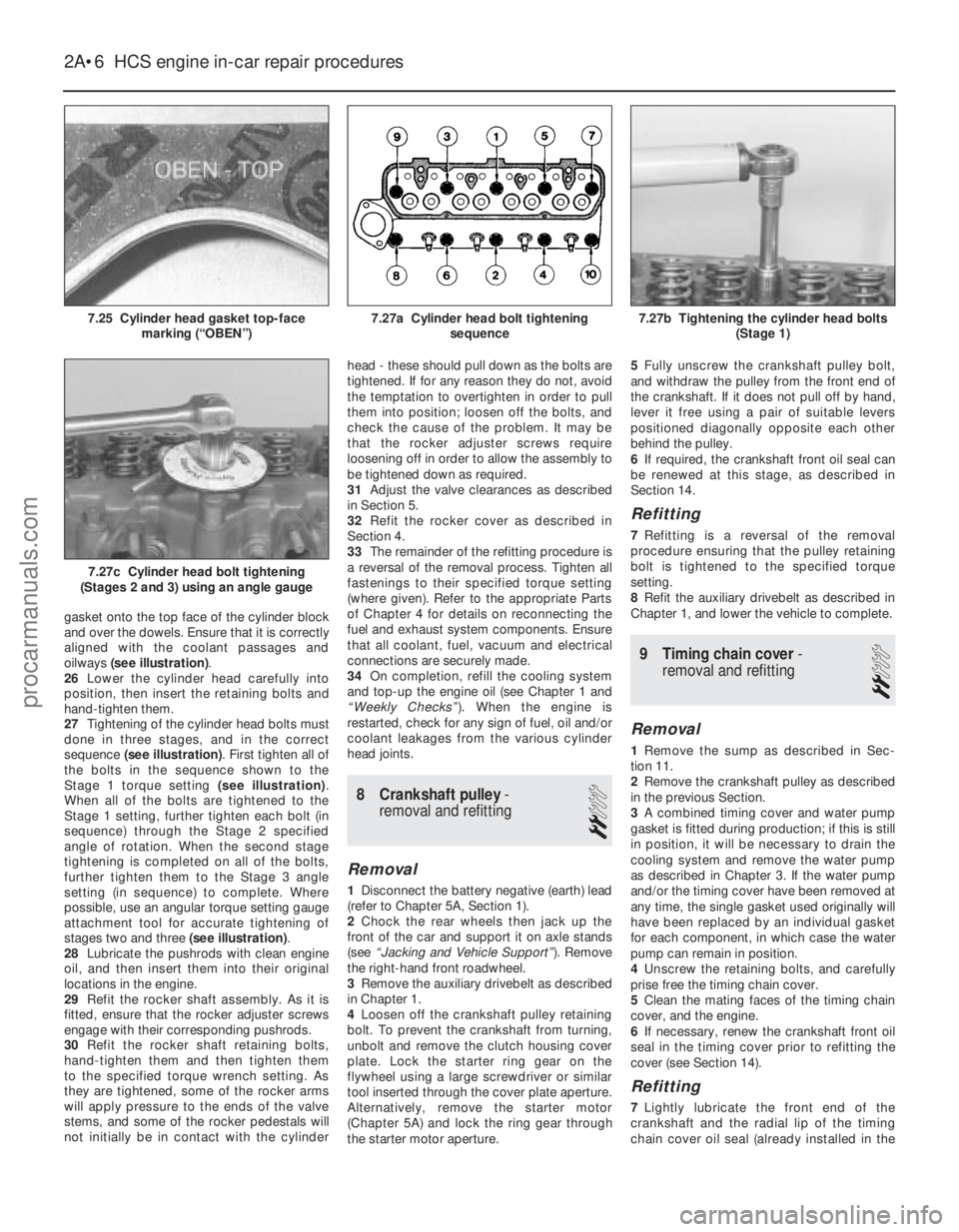
gasket onto the top face of the cylinder block
and over the dowels. Ensure that it is correctly
aligned with the coolant passages and
oilways (see illustration) .
26 Lower the cylinder head carefully into
position, then insert the retaining bolts and
hand-tighten them.
27 Tightening of the cylinder head bolts must
done in three stages, and in the correct
sequence (see illustration) . First tighten all of
the bolts in the sequence shown to the
Stage 1 torque setting (see illustration).
When all of the bolts are tightened to the
Stage 1 setting, further tighten each bolt (in
sequence) through the Stage 2 specified
angle of rotation. When the second stage
tightening is completed on all of the bolts,
further tighten them to the Stage 3 angle
setting (in sequence) to complete. Where
possible, use an angular torque setting gauge
attachment tool for accurate tightening of
stages two and three (see illustration).
28 Lubricate the pushrods with clean engine
oil, and then insert them into their original
locations in the engine.
29 Refit the rocker shaft assembly. As it is
fitted, ensure that the rocker adjuster screws
engage with their corresponding pushrods.
30 Refit the rocker shaft retaining bolts,
hand-tighten them and then tighten them
to the specified torque wrench setting. As
they are tightened, some of the rocker arms
will apply pressure to the ends of the valve
stems, and some of the rocker pedestals will
not initially be in contact with the cylinder head - these should pull down as the bolts are
tightened. If for any reason they do not, avoid
the temptation to overtighten in order to pull
them into position; loosen off the bolts, and
check the cause of the problem. It may be
that the rocker adjuster screws require
loosening off in order to allow the assembly to
be tightened down as required.
31
Adjust the valve clearances as described
in Section 5.
32 Refit the rocker cover as described in
Section 4.
33 The remainder of the refitting procedure is
a reversal of the removal process. Tighten all
fastenings to their specified torque setting
(where given). Refer to the appropriate Parts
of Chapter 4 for details on reconnecting the
fuel and exhaust system components. Ensure
that all coolant, fuel, vacuum and electrical
connections are securely made.
34 On completion, refill the cooling system
and top-up the engine oil (see Chapter 1 and
“Weekly Checks” ). When the engine is
restarted, check for any sign of fuel, oil and/or
coolant leakages from the various cylinder
head joints.
8 Crankshaft pulley -
removal and refitting
2
Removal
1 Disconnect the battery negative (earth) lead
(refer to Chapter 5A, Section 1).
2 Chock the rear wheels then jack up the
front of the car and support it on axle stands
(see “Jacking and Vehicle Support” ). Remove
the right-hand front roadwheel.
3 Remove the auxiliary drivebelt as described
in Chapter 1.
4 Loosen off the crankshaft pulley retaining
bolt. To prevent the crankshaft from turning,
unbolt and remove the clutch housing cover
plate. Lock the starter ring gear on the
flywheel using a large screwdriver or similar
tool inserted through the cover plate aperture.
Alternatively, remove the starter motor
(Chapter 5A) and lock the ring gear through
the starter motor aperture. 5
Fully unscrew the crankshaft pulley bolt,
and withdraw the pulley from the front end of
the crankshaft. If it does not pull off by hand,
lever it free using a pair of suitable levers
positioned diagonally opposite each other
behind the pulley.
6 If required, the crankshaft front oil seal can
be renewed at this stage, as described in
Section 14.
Refitting
7 Refitting is a reversal of the removal
procedure ensuring that the pulley retaining
bolt is tightened to the specified torque
setting.
8 Refit the auxiliary drivebelt as described in
Chapter 1, and lower the vehicle to complete.
9 Timing chain cover -
removal and refitting
2
Removal
1 Remove the sump as described in Sec-
tion 11.
2 Remove the crankshaft pulley as described
in the previous Section.
3 A combined timing cover and water pump
gasket is fitted during production; if this is still
in position, it will be necessary to drain the
cooling system and remove the water pump
as described in Chapter 3. If the water pump
and/or the timing cover have been removed at
any time, the single gasket used originally will
have been replaced by an individual gasket
for each component, in which case the water
pump can remain in position.
4 Unscrew the retaining bolts, and carefully
prise free the timing chain cover.
5 Clean the mating faces of the timing chain
cover, and the engine.
6 If necessary, renew the crankshaft front oil
seal in the timing cover prior to refitting the
cover (see Section 14).
Refitting
7 Lightly lubricate the front end of the
crankshaft and the radial lip of the timing
chain cover oil seal (already installed in the
2A•6 HCS engine in-car repair procedures
7.27c Cylinder head bolt tightening
(Stages 2 and 3) using an angle gauge
7.27b Tightening the cylinder head bolts (Stage 1)7.27a Cylinder head bolt tighteningsequence7.25 Cylinder head gasket top-facemarking (“OBEN”)
1595Ford Fiesta Remakeprocarmanuals.com
http://vnx.su
Page 43 of 296
complete turn, and all the markings should
now align.
7With the engine set at No 1 piston on TDC
compression, refit the crankshaft pulley cover,
lower the vehicle and refit the upper timing
belt cover.
4 Cylinder head rocker cover -
removal and refitting
2
Removal
1 Disconnect the battery negative (earth) lead
(refer to Chapter 5A, Section 1).
2 Remove the air cleaner assembly and air
inlet components as necessary for access as
described in the relevant Part of Chapter 4.
Disconnect the crankcase ventilation hose
from the rocker cover.
3 Remove the timing belt upper cover as
described in Section 7.
4 Referring to the relevant Part of Chapter 4
for details, disconnect the accelerator cable
from the throttle linkage and from the adjuster
bracket above the rocker cover. Position the
cable out of the way.
5 Where applicable, disconnect the choke
cable from the carburettor, referring to
Chapter 4A for details.
6 Unscrew and remove the rocker cover
retaining bolts and washers, then lift the cover
from the cylinder head. Note that a new
rocker cover gasket will be needed on
refitting.
Refitting
7 Before refitting the rocker cover, clean the
mating surfaces of both the cylinder head and
the cover.
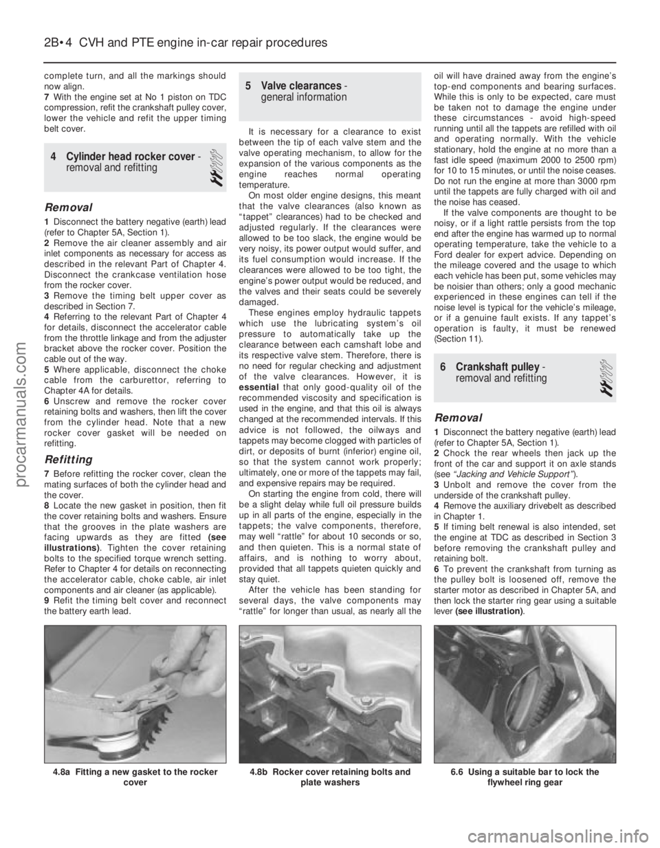
8 Locate the new gasket in position, then fit
the cover retaining bolts and washers. Ensure
that the grooves in the plate washers are
facing upwards as they are fitted (see
illustrations) . Tighten the cover retaining
bolts to the specified torque wrench setting.
Refer to Chapter 4 for details on reconnecting
the accelerator cable, choke cable, air inlet
components and air cleaner (as applicable).
9 Refit the timing belt cover and reconnect
the battery earth lead.
5 Valve clearances -
general information
It is necessary for a clearance to exist
between the tip of each valve stem and the
valve operating mechanism, to allow for the
expansion of the various components as the
engine reaches normal operating
temperature. On most older engine designs, this meant
that the valve clearances (also known as
“tappet” clearances) had to be checked and
adjusted regularly. If the clearances were
allowed to be too slack, the engine would be
very noisy, its power output would suffer, and
its fuel consumption would increase. If the
clearances were allowed to be too tight, the
engine’s power output would be reduced, and
the valves and their seats could be severely
damaged. These engines employ hydraulic tappets
which use the lubricating system’s oil
pressure to automatically take up the
clearance between each camshaft lobe and
its respective valve stem. Therefore, there is
no need for regular checking and adjustment
of the valve clearances. However, it is
essential that only good-quality oil of the
recommended viscosity and specification is
used in the engine, and that this oil is always
changed at the recommended intervals. If this
advice is not followed, the oilways and
tappets may become clogged with particles of
dirt, or deposits of burnt (inferior) engine oil,
so that the system cannot work properly;
ultimately, one or more of the tappets may fail,
and expensive repairs may be required. On starting the engine from cold, there will
be a slight delay while full oil pressure builds
up in all parts of the engine, especially in the
tappets; the valve components, therefore,
may well “rattle” for about 10 seconds or so,
and then quieten. This is a normal state of
affairs, and is nothing to worry about,
provided that all tappets quieten quickly and
stay quiet. After the vehicle has been standing for
several days, the valve components may
“rattle” for longer than usual, as nearly all the oil will have drained away from the engine’s
top-end components and bearing surfaces.
While this is only to be expected, care must
be taken not to damage the engine under
these circumstances - avoid high-speed
running until all the tappets are refilled with oil
and operating normally. With the vehicle
stationary, hold the engine at no more than a
fast idle speed (maximum 2000 to 2500 rpm)
for 10 to 15 minutes, or until the noise ceases.
Do not run the engine at more than 3000 rpm
until the tappets are fully charged with oil and
the noise has ceased.
If the valve components are thought to be
noisy, or if a light rattle persists from the top
end after the engine has warmed up to normal
operating temperature, take the vehicle to a
Ford dealer for expert advice. Depending on
the mileage covered and the usage to which
each vehicle has been put, some vehicles may
be noisier than others; only a good mechanic
experienced in these engines can tell if the
noise level is typical for the vehicle’s mileage,
or if a genuine fault exists. If any tappet’s
operation is faulty, it must be renewed
(Section 11).
6 Crankshaft pulley -
removal and refitting
2
Removal
1 Disconnect the battery negative (earth) lead
(refer to Chapter 5A, Section 1).
2 Chock the rear wheels then jack up the
front of the car and support it on axle stands
(see “Jacking and Vehicle Support” ).
3 Unbolt and remove the cover from the
underside of the crankshaft pulley.
4 Remove the auxiliary drivebelt as described
in Chapter 1.
5 If timing belt renewal is also intended, set
the engine at TDC as described in Section 3
before removing the crankshaft pulley and
retaining bolt.
6 To prevent the crankshaft from turning as
the pulley bolt is loosened off, remove the
starter motor as described in Chapter 5A, and
then lock the starter ring gear using a suitable
lever (see illustration) .
2B•4 CVH and PTE engine in-car repair procedures
6.6 Using a suitable bar to lock the
flywheel ring gear4.8b Rocker cover retaining bolts and plate washers4.8a Fitting a new gasket to the rocker cover
1595Ford Fiesta Remakeprocarmanuals.com
http://vnx.su
Page 48 of 296
23Refer to the procedure in Section 9 when
refitting the camshaft sprocket.
24 Refit and tension the timing belt as
described in Section 8.
25 Lubricate the hydraulic tappets with
hypoid oil before refitting them into their
original locations in the cylinder head.
26 Lubricate and refit the rocker arms and
guides in their original sequence, use new
nuts and tighten them to the specified torque
setting. It is essential, before each rocker arm
is installed and its nut tightened, that the
respective cam follower is positioned at its
lowest point (in contact with the cam base
circle). Turn the cam (using the crankshaft
pulley bolt) as necessary to achieve this.
27 Refit the rocker cover as described in
Section 4.
28 Refit the remaining components with
reference to the relevant Sections in this
Chapter or elsewhere in the manual.
29 On completion, reconnect the battery
negative lead.
12 Cylinder head -
removal and refitting
4
Removal
Note: The following procedure describes
removal and refitting of the cylinder head
complete with inlet and exhaust manifolds. If
wished, the manifolds may be removed first,
as described in the relevant Part of Chapter 4,
and the cylinder head then removed on its
own.
1 On fuel-injected engines, depressurise the
fuel system as described in Chapter 4B or 4C.
2 Disconnect the battery negative (earth) lead
(refer to Chapter 5A, Section 1).
3 Refer to Chapter 1 and drain the cooling
system. 4
Remove the rocker cover as described in
Section 4.
5 Disconnect the accelerator and choke
cables as applicable (refer to the relevant Part
of Chapter 4).
6 Loosen off the retaining clips and
disconnect the upper coolant hose, the
expansion tank hose and the heater hose
from the thermostat housing. Also disconnect
the heater hose from the inlet manifold.
7 On CFi models, disconnect the heated
coolant hose from the injector unit.
8 On EFi and SEFi models, disconnect the
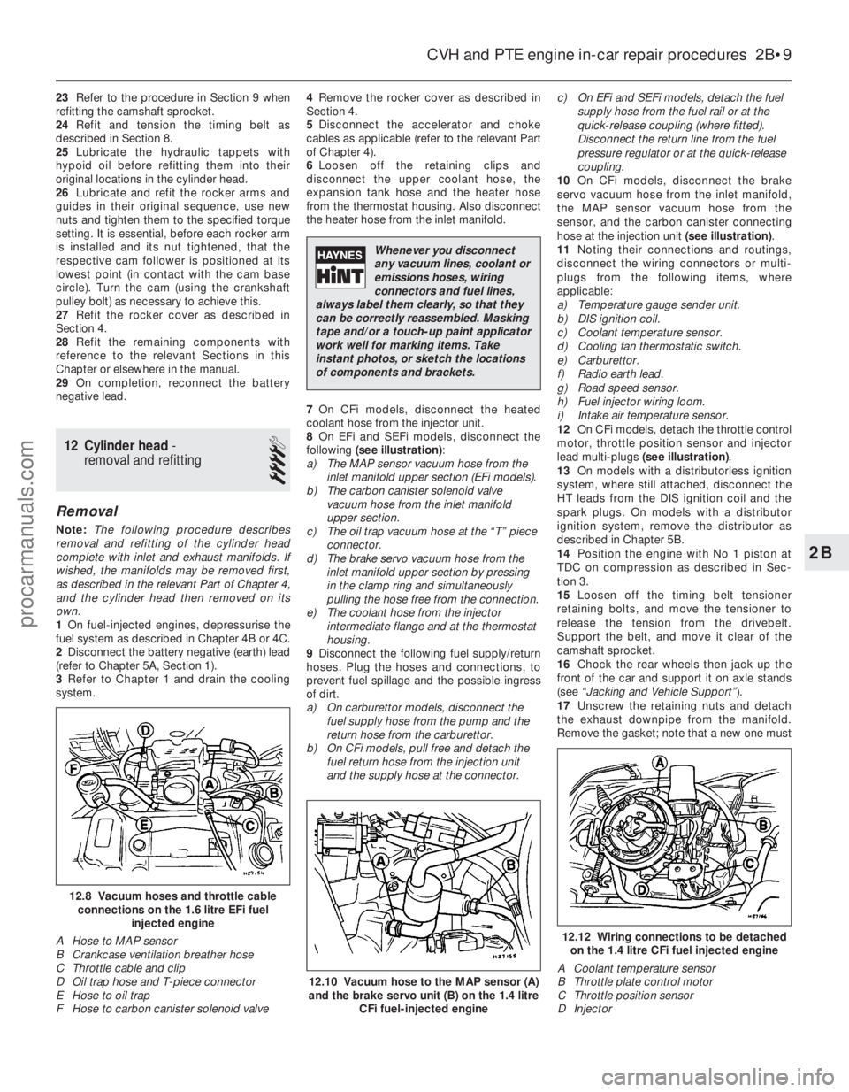
following (see illustration) :
a) The MAP sensor vacuum hose from the inlet manifold upper section (EFi models).
b) The carbon canister solenoid valve
vacuum hose from the inlet manifold
upper section.
c) The oil trap vacuum hose at the “T” piece
connector.
d) The brake servo vacuum hose from the
inlet manifold upper section by pressing
in the clamp ring and simultaneously
pulling the hose free from the connection.
e) The coolant hose from the injector
intermediate flange and at the thermostat
housing.
9 Disconnect the following fuel supply/return
hoses. Plug the hoses and connections, to
prevent fuel spillage and the possible ingress
of dirt.
a) On carburettor models, disconnect the fuel supply hose from the pump and the
return hose from the carburettor.
b) On CFi models, pull free and detach the
fuel return hose from the injection unit
and the supply hose at the connector. c) On EFi and SEFi models, detach the fuel
supply hose from the fuel rail or at the
quick-release coupling (where fitted).
Disconnect the return line from the fuel
pressure regulator or at the quick-release
coupling.
10 On CFi models, disconnect the brake
servo vacuum hose from the inlet manifold,
the MAP sensor vacuum hose from the
sensor, and the carbon canister connecting
hose at the injection unit (see illustration).
11 Noting their connections and routings,
disconnect the wiring connectors or multi-
plugs from the following items, where
applicable:
a) Temperature gauge sender unit.
b) DIS ignition coil.
c) Coolant temperature sensor.
d) Cooling fan thermostatic switch.
e) Carburettor.
f) Radio earth lead.
g) Road speed sensor.
h) Fuel injector wiring loom.
i) Intake air temperature sensor.
12 On CFi models, detach the throttle control
motor, throttle position sensor and injector
lead multi-plugs (see illustration) .
13 On models with a distributorless ignition
system, where still attached, disconnect the
HT leads from the DIS ignition coil and the
spark plugs. On models with a distributor
ignition system, remove the distributor as
described in Chapter 5B.
14 Position the engine with No 1 piston at
TDC on compression as described in Sec-
tion 3.
15 Loosen off the timing belt tensioner
retaining bolts, and move the tensioner to
release the tension from the drivebelt.
Support the belt, and move it clear of the
camshaft sprocket.
16 Chock the rear wheels then jack up the
front of the car and support it on axle stands
(see “Jacking and Vehicle Support” ).
17 Unscrew the retaining nuts and detach
the exhaust downpipe from the manifold.
Remove the gasket; note that a new one must
CVH and PTE engine in-car repair procedures 2B•9
12.12 Wiring connections to be detached on the 1.4 litre CFi fuel injected engine
A Coolant temperature sensor
B Throttle plate control motor
C Throttle position sensor
D Injector
12.10 Vacuum hose to the MAP sensor (A)
and the brake servo unit (B) on the 1.4 litre
CFi fuel-injected engine
12.8 Vacuum hoses and throttle cableconnections on the 1.6 litre EFi fuel injected engine
A Hose to MAP sensor
B Crankcase ventilation breather hose
C Throttle cable and clip
D Oil trap hose and T-piece connector
E Hose to oil trap
F Hose to carbon canister solenoid valve
2B
1595Ford Fiesta Remake
Whenever you disconnect
any vacuum lines, coolant or
emissions hoses, wiring
connectors and fuel lines,
always label them clearly, so that they
can be correctly reassembled. Masking
tape and/or a touch-up paint applicator
work well for marking items. Take
instant photos, or sketch the locations
of components and brackets.
procarmanuals.com
http://vnx.su
Page 49 of 296
be fitted on reassembly. Tie the downpipe up
to support it.
18Before it is released and removed, the
cylinder head must first have cooled down to
room temperature (about 20ºC).
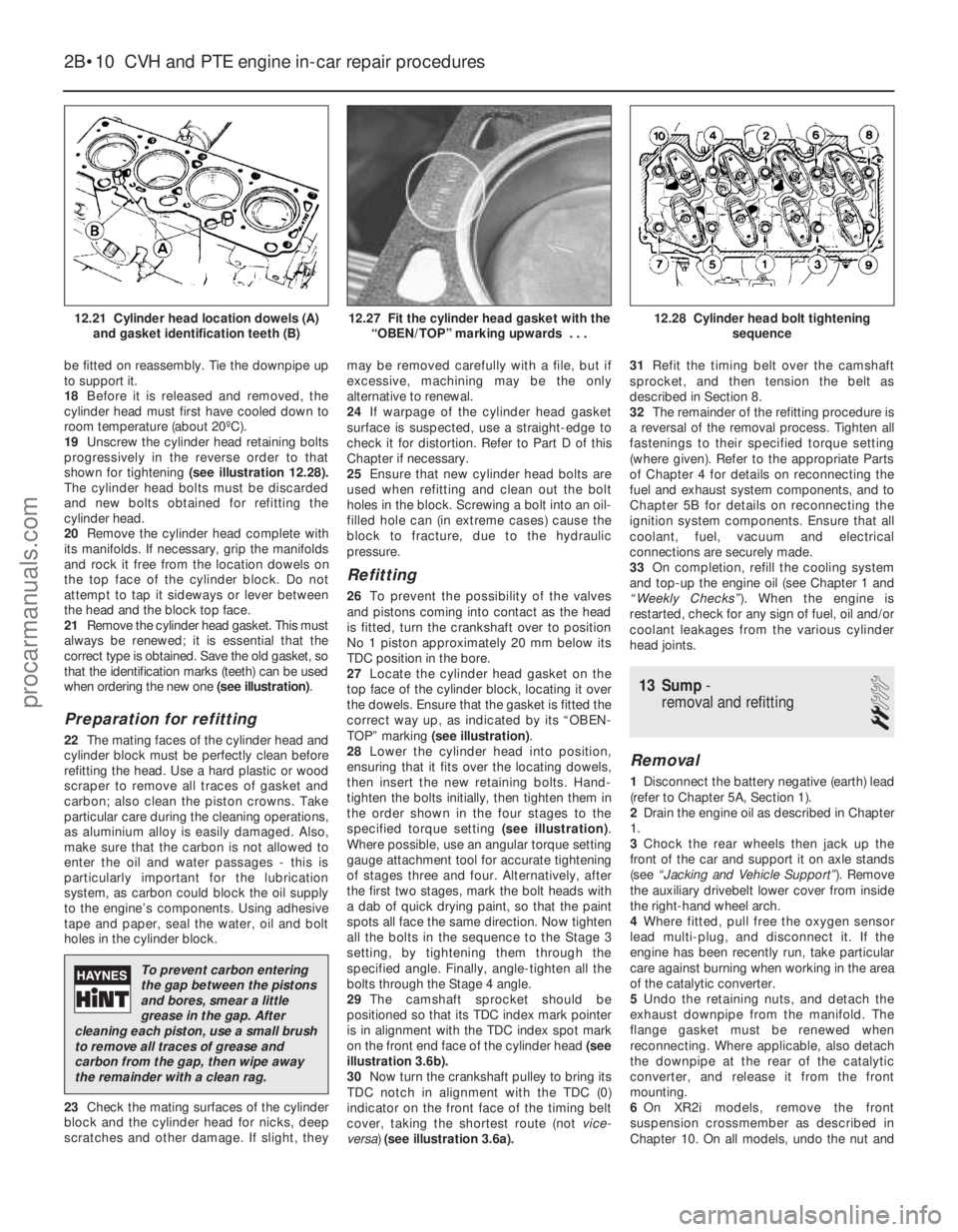
19 Unscrew the cylinder head retaining bolts
progressively in the reverse order to that
shown for tightening (see illustration 12.28).
The cylinder head bolts must be discarded
and new bolts obtained for refitting the
cylinder head.
20 Remove the cylinder head complete with
its manifolds. If necessary, grip the manifolds
and rock it free from the location dowels on
the top face of the cylinder block. Do not
attempt to tap it sideways or lever between
the head and the block top face.
21 Remove the cylinder head gasket. This must
always be renewed; it is essential that the
correct type is obtained. Save the old gasket, so
that the identification marks (teeth) can be used
when ordering the new one (see illustration).
Preparation for refitting
22The mating faces of the cylinder head and
cylinder block must be perfectly clean before
refitting the head. Use a hard plastic or wood
scraper to remove all traces of gasket and
carbon; also clean the piston crowns. Take
particular care during the cleaning operations,
as aluminium alloy is easily damaged. Also,
make sure that the carbon is not allowed to
enter the oil and water passages - this is
particularly important for the lubrication
system, as carbon could block the oil supply
to the engine’s components. Using adhesive
tape and paper, seal the water, oil and bolt
holes in the cylinder block.
23 Check the mating surfaces of the cylinder
block and the cylinder head for nicks, deep
scratches and other damage. If slight, they may be removed carefully with a file, but if
excessive, machining may be the only
alternative to renewal.
24
If warpage of the cylinder head gasket
surface is suspected, use a straight-edge to
check it for distortion. Refer to Part D of this
Chapter if necessary.
25 Ensure that new cylinder head bolts are
used when refitting and clean out the bolt
holes in the block. Screwing a bolt into an oil-
filled hole can (in extreme cases) cause the
block to fracture, due to the hydraulic
pressure.
Refitting
26 To prevent the possibility of the valves
and pistons coming into contact as the head
is fitted, turn the crankshaft over to position
No 1 piston approximately 20 mm below its
TDC position in the bore.
27 Locate the cylinder head gasket on the
top face of the cylinder block, locating it over
the dowels. Ensure that the gasket is fitted the
correct way up, as indicated by its “OBEN-
TOP” marking (see illustration) .
28 Lower the cylinder head into position,
ensuring that it fits over the locating dowels,
then insert the new retaining bolts. Hand-
tighten the bolts initially, then tighten them in
the order shown in the four stages to the
specified torque setting (see illustration).
Where possible, use an angular torque setting
gauge attachment tool for accurate tightening
of stages three and four. Alternatively, after
the first two stages, mark the bolt heads with
a dab of quick drying paint, so that the paint
spots all face the same direction. Now tighten
all the bolts in the sequence to the Stage 3
setting, by tightening them through the
specified angle. Finally, angle-tighten all the
bolts through the Stage 4 angle.
29 The camshaft sprocket should be
positioned so that its TDC index mark pointer
is in alignment with the TDC index spot mark
on the front end face of the cylinder head (see
illustration 3.6b).
30 Now turn the crankshaft pulley to bring its
TDC notch in alignment with the TDC (0)
indicator on the front face of the timing belt
cover, taking the shortest route (not vice-
versa) (see illustration 3.6a). 31
Refit the timing belt over the camshaft
sprocket, and then tension the belt as
described in Section 8.
32 The remainder of the refitting procedure is
a reversal of the removal process. Tighten all
fastenings to their specified torque setting
(where given). Refer to the appropriate Parts
of Chapter 4 for details on reconnecting the
fuel and exhaust system components, and to
Chapter 5B for details on reconnecting the
ignition system components. Ensure that all
coolant, fuel, vacuum and electrical
connections are securely made.
33 On completion, refill the cooling system
and top-up the engine oil (see Chapter 1 and
“Weekly Checks” ). When the engine is
restarted, check for any sign of fuel, oil and/or
coolant leakages from the various cylinder
head joints.
13 Sump -
removal and refitting
2
Removal
1 Disconnect the battery negative (earth) lead
(refer to Chapter 5A, Section 1).
2 Drain the engine oil as described in Chapter
1.
3 Chock the rear wheels then jack up the
front of the car and support it on axle stands
(see “Jacking and Vehicle Support” ). Remove
the auxiliary drivebelt lower cover from inside
the right-hand wheel arch.
4 Where fitted, pull free the oxygen sensor
lead multi-plug, and disconnect it. If the
engine has been recently run, take particular
care against burning when working in the area
of the catalytic converter.
5 Undo the retaining nuts, and detach the
exhaust downpipe from the manifold. The
flange gasket must be renewed when
reconnecting. Where applicable, also detach
the downpipe at the rear of the catalytic
converter, and release it from the front
mounting.
6 On XR2i models, remove the front
suspension crossmember as described in
Chapter 10. On all models, undo the nut and
2B•10 CVH and PTE engine in-car repair procedures
12.28 Cylinder head bolt tightening
sequence12.27 Fit the cylinder head gasket with the“OBEN/TOP” marking upwards . . .12.21 Cylinder head location dowels (A)and gasket identification teeth (B)
1595Ford Fiesta Remake
To prevent carbon entering
the gap between the pistons
and bores, smear a little
grease in the gap. After
cleaning each piston, use a small brush
to remove all traces of grease and
carbon from the gap, then wipe away
the remainder with a clean rag.
procarmanuals.com
http://vnx.su
Page 63 of 296
caps. Tighten the bearing cap bolts to the
specified torque wrench setting, then
measure the endfloat using a DTI (Dial Test
Indicator, or dial gauge) mounted on the
cylinder head so that its tip bears on the
camshaft right-hand end.
16Tap the camshaft fully towards the gauge,
zero the gauge, then tap the camshaft fully
away from the gauge, and note the gauge
reading. If the endfloat measured is found to
be at or beyond the specified service limit, fit
a new camshaft and repeat the check; if the
clearance is still excessive, the cylinder head
must be renewed.
Refitting
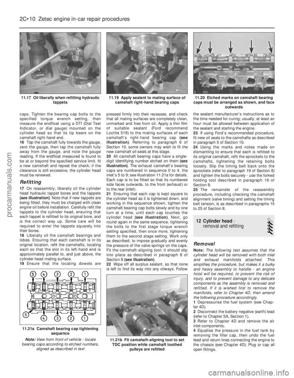
17 On reassembly, liberally oil the cylinder
head hydraulic tappet bores and the tappets
(see illustration) . Note that if new tappets are
being fitted, they must be charged with clean
engine oil before installation. Carefully refit the
tappets to the cylinder head, ensuring that
each tappet is refitted to its original bore, and
is the correct way up. Some care will be
required to enter the tappets squarely into
their bores.
18 Liberally oil the camshaft bearings and
lobes. Ensuring that each camshaft is in its
original location, refit the camshafts, locating
each so that the slot in its left-hand end is
approximately parallel to, and just above, the
cylinder head mating surface.
19 Ensure that the locating dowels are pressed firmly into their recesses, and check
that all mating surfaces are completely clean,
unmarked and free from oil. Apply a thin film
of suitable sealant (Ford recommend
Loctite 518) to the mating surfaces of each
camshaft’s right-hand bearing cap
(see
illustration) . Referring to paragraph 6 of
Section 10, some owners may wish to fit the
new camshaft oil seals at this stage.
20 All camshaft bearing caps have a single-
digit identifying number etched on them (see
illustration) . The exhaust camshaft’s bearing
caps are numbered in sequence 0 to 4, the
inlet’s 5 to 9; see illustration 11.21a for details.
Each cap is to be fitted so that its numbered
side faces outwards, to the front (exhaust) or
to the rear (inlet).
21 Ensuring that each cap is kept square to
the cylinder head as it is tightened down, and
working in the sequence shown, tighten the
camshaft bearing cap bolts slowly and by one
turn at a time, until each cap touches the
cylinder head (see illustration) . Next, go
round again in the same sequence, tightening
the bolts to the first stage torque wrench
setting specified, then once more, tightening
them to the second stage setting. Work only
as described, to impose gradually and evenly
the pressure of the valve springs on the caps.
Fit the camshaft-aligning tool; it should slip
into place as described in paragraph 8 of
Section 8 (see illustration) .
22 Wipe off all surplus sealant, so that none
is left to find its way into any oilways. Follow the sealant manufacturer’s instructions as to
the time needed for curing; usually, at least an
hour must be allowed between application of
the sealant and starting the engine.
23
If using Ford’s recommended procedure,
fit new oil seals to the camshafts as described
in paragraph 5 of Section 10.
24 Using the marks and notes made on
dismantling to ensure that each is refitted to
its original camshaft, refit the sprockets to the
camshafts, tightening the retaining bolts
loosely. Slip the timing belt back onto the
sprockets (refer to paragraph 19 of Section 8)
and tighten the bolts securely - use the forked
holding tool described in paragraph 16 of
Section 8.
25 The remainder of the reassembly
procedure, including checking the camshaft
alignment (valve timing) and setting the timing
belt tension, is as described in paragraphs 15
to 25 of Section 8.
12 Cylinder head -
removal and refitting
4
Removal
Note: The following text assumes that the
cylinder head will be removed with both inlet
and exhaust manifolds attached. This
simplifies the procedure, but makes it a bulky
and heavy assembly to handle - an engine
hoist will be required, to prevent the risk of
injury, and to prevent damage to any delicate
components as the assembly is removed and
refitted. If it is wished first to remove the
manifolds, refer to Chapter 4D, then amend
the following procedure accordingly.
1 Depressurise the fuel system (see Chap-
ter 4D).
2 Disconnect the battery negative (earth) lead
(refer to Chapter 5A, Section 1).
3 Refer to Chapter 4D and remove the air
inlet components.
4 Equalise the pressure in the fuel tank by
removing the filler cap, then undo the fuel
feed and return lines connecting the engine to
the chassis (see Chapter 4D). Plug or cap all
open fittings.
2C•10 Zetec engine in-car repair procedures
11.21b Fit camshaft-aligning tool to set TDC position while camshaft toothed
pulleys are refitted
11.21a Camshaft bearing cap tightening sequence
Note: View from front of vehicle - locate
bearing caps according to etched numbers, aligned as described in text
11.20 Etched marks on camshaft bearing
caps must be arranged as shown, and face outwards11.19 Apply sealant to mating surface ofcamshaft right-hand bearing caps11.17 Oil liberally when refitting hydraulic tappets
1595Ford Fiesta Remakeprocarmanuals.com
http://vnx.su
Page 64 of 296
5Disconnect the accelerator cable from the
throttle linkage as described in Chapter 4D.
Secure the cable clear of the engine/
transmission.
6 Remove the auxiliary drivebelt (see Chap-
ter 1).
7 Remove the three screws securing the
wiring “rail” to the rear of the manifold.
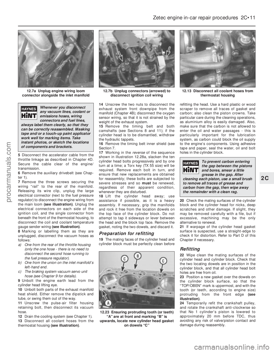
Releasing its wire clip, unplug the large
electrical connector (next to the fuel pressure
regulator) to disconnect the engine wiring from
the main loom (see illustration) . Unplug the
electrical connectors on each side of the
ignition coil, and the single connector from
beneath the front of the thermostat housing, to
disconnect the coil and coolant temperature
gauge sender wiring (see illustration).
8 Marking or labelling them as they are
unplugged, disconnect the vacuum hoses as
follows:
a) One from the rear of the throttle housing
(only the one hose - there is no need to
disconnect the second hose running to
the fuel pressure regulator).
b) One from the union on the inlet manifold’s
left-hand end.
c) The braking system vacuum servo unit hose (see Chapter 9 for details).
9 Unbolt the engine earth lead from the
cylinder head lifting eye.
10 Unbolt both parts of the exhaust manifold
heat shield. Either remove the dipstick and
tube, or swing them out of the way.
11 Unscrew the pulse-air filter housing
retaining bolt, then disconnect its vacuum
hose.
12 Drain the cooling system (see Chapter 1).
13 Disconnect all coolant hoses from the
thermostat housing (see illustration).14
Unscrew the two nuts to disconnect the
exhaust system front downpipe from the
manifold (Chapter 4B); disconnect the oxygen
sensor wiring, so that it is not strained by the
weight of the exhaust system.
15 Remove the timing belt and both
camshafts (see Sections 8 and 11); if the
cylinder head is to be dismantled, withdraw
the hydraulic tappets.
16 Remove the timing belt inner shield (see
Section 7.
17 Working in the reverseof the sequence
shown in illustration 12.28a, slacken the ten
cylinder head bolts progressively and by one
turn at a time; a Torx key (TX 55 size) will be
required. Remove each bolt in turn, and
ensure that new replacements are obtained
for reassembly; these bolts are subjected to
severe stresses and so mustbe renewed,
regardless of their apparent condition,
whenever they are disturbed.
18 Lift the cylinder head away; use
assistance if possible, as it is a heavy
assembly. If necessary, grip the manifolds
and rock it free from the location dowels on
the top face of the cylinder block. Do not
attempt to tap it sideways or lever between
the head and the block top face. Remove the
gasket, noting the two dowels, and discard it.
Preparation for refitting
19 The mating faces of the cylinder head and
cylinder block must be perfectly clean before refitting the head. Use a hard plastic or wood
scraper to remove all traces of gasket and
carbon; also clean the piston crowns. Take
particular care during the cleaning operations,
as aluminium alloy is easily damaged. Also,
make sure that the carbon is not allowed to
enter the oil and water passages - this is
particularly important for the lubrication
system, as carbon could block the oil supply
to the engine’s components. Using adhesive
tape and paper, seal the water, oil and bolt
holes in the cylinder block.
20
Check the mating surfaces of the cylinder
block and the cylinder head for nicks, deep
scratches and other damage. If slight, they
may be removed carefully with a file, but if
excessive, machining may be the only
alternative to renewal.
21 If warpage of the cylinder head gasket
surface is suspected, use a straight-edge to
check it for distortion. Refer to Part D of this
Chapter if necessary.
Refitting
22 Wipe clean the mating surfaces of the
cylinder head and cylinder block. Check that
the two locating dowels are in position in the
cylinder block, and that all cylinder head bolt
holes are free from oil.
23 Position a new gasket over the dowels on
the cylinder block surface, so that the
“TOP/OBEN” mark is uppermost, and with the
tooth (or teeth, according to engine size)
protruding from the front edge (see
illustration) .
24 Temporarily refit the crankshaft pulley,
and rotate the crankshaft anti-clockwise so
that No 1 cylinder’s piston is lowered to
approximately 20 mm before TDC, thus
avoiding any risk of valve/piston contact and
damage during reassembly.
Zetec engine in-car repair procedures 2C•11
12.13 Disconnect all coolant hoses from thermostat housing12.7b Unplug connectors (arrowed) todisconnect ignition coil wiring12.7a Unplug engine wiring loom
connector alongside the inlet manifold
12.23 Ensuring protruding tooth (or teeth) “A” are at front and marking “B” is
upwards, locate new cylinder head gasket on dowels “C”
2C
1595Ford Fiesta Remake
Whenever you disconnect
any vacuum lines, coolant or
emissions hoses, wiring
connectors and fuel lines,
always label them clearly, so that they
can be correctly reassembled. Masking
tape and/or a touch-up paint applicator
work well for marking items. Take
instant photos, or sketch the locations
of components and brackets.
To prevent carbon entering
the gap between the pistons
and bores, smear a little
grease in the gap. After
cleaning each piston, use a small brush
to remove all traces of grease and
carbon from the gap, then wipe away
the remainder with a clean rag.
procarmanuals.com
http://vnx.su