1988 PONTIAC FIERO light
[x] Cancel search: lightPage 114 of 1825
CHASSIS SHEET METAL 2@-7
3. During the above flash time period (1 to 10 min-
utes), apply appropriate "conventional" interior acrylic lacquer color as required and allow
painted part to dry for
4 to 5 hours before install-
ing on car.
RlGlD OW HARD ABS PMS"TIC PARTS
Rigid or hard ABS plastic requires no primer.
"Conventional" interior acrylic lacquers adhere satis-
factorily to hard ABS plastics.
Procedure
1. Wash part thoroughly with a cleaning solvent
(Acrylic-Clean, Pre-Kleano, Prep-Sol or equiv-
alent) to remove any dirt or grease.
2. Apply appropriate "conventional" interior
acrylic lacquer color. Apply only sufficient
color for proper hiding to avoid washout of
"grain" effect.
3. Allow to dry and then install part.
VINYL AND FLEXIBLE (Son) ABS
PLASTIC PARTS
The outer cover or skin material of "flexible"
instrument panel cover (pad) assemblies is made of an
ABSIPVC plastic blend. The same is true of many
"padded" door trim assemblies. The soft cushion pad-
ding under the I.P. skin is urethane foam plastic. The
most widely used
"flexible" vinyls (poly vinyl chlo-
ride)
are coated fabrics, such as used in seat trim,
some door trim assemblies, molded headlining panels
and sun visors. Most head rests are "flexible" vinyls.
Examples of "hard vinyls are: door and front seat
back assist handles and coat hooks.
The paint system of vinyl and flexible ABS
plastic involves the use of interior "vinyl" color and a
clear vinyl top coat.
Procedure
1. Wash part thoroughly with a vinyl cleaning and
preparation solvent ("Vinyl Press"
- Ditzler,
"Vinyl Prep Conditioner"
- Detroit Autobody
or equivalent) to remove greasy film or silicone.
Wipe off cleaner while still wet with clean,
lint-
free cloth.
2. Immediately after wiping face dry, apply inte-
rior "vinyl" color in wet coats allowing suffi-
cient flash time between coats (see label
directions on can). Use proper "vinyl" color as
designated by interior trim combinations. Apply
only sufficient color for proper hiding to avoid
washout of "grain" effect. No primer or
primer-
sealer is required.
3. Before the final vinyl color coat has dried, apply
two coats of clear vinyl top coat spray (instru-
ment panels will require the "nonglare" clear top
coat). Do not allow the first spray coat to com-
pletely dry before spraying on the second. Use
top coat with appropriate gloss level to match adjacent similar components. This
clear coat is
necessary to control the gloss requirement and
prevent
'tracking" (rubbing-off) of the color
coat after drying.
4. Allow to dry according to label directions before
installing part.
ON-VEHICLE SERVICE
CONCEALED HEADLIGHTS
The concealed headlights used on this model are
electrically operated. When the headlights are turned
on, solid state circuitry activates the actuators. This
same circuitry senses when the actuators stop moving
and removes the ground to deactivate the actuators.
When the headlights are turned off, the actuators run
in opposite direction closing the headlight doors.
Should an electrical failure occur in the head-
light circuit, they may be raised manually by rotating
the knob on the actuator in a counterclockwise direc-
tion until the headlights are fully open. The headlights
may be lowered by rotating the knob on the actuator in
a clockwise direction until the headlights are fully
closed.
For electrical circuit information and diagnosis,
refer to Section
8A of this manual.
If it is desired to raise the headlights with the
lights off, either of the following procedures may be
used:
1. Turn the lights on. After the headlights are
open, disconnect the electrical connections at
the actuator connectors. Turn the lights off. The
headlights will now remain in the open position.
2. Turn the parking lights on. Depress the head-
light rocker switch lightly. The headlights may
then be raised "up" fully with the lights off.
Adjust
Because of the number of adjustments possible
and the number of attaching points of the concealed
headlight body assembly
(9), only those attachments
which control the adjustment desired should be loos-
ened. Make one
adjbstment at a time.
NOTICE: The headlight door does NOT have
slotted mounting holes and therefore is not
adjustable by itself. This insures proper clearance
between the headlight door and the hood and
fenders in both the raised and lowered positions.
The entire headlight body assembly must be
adjusted to achieve the desired appearance and
fit. Care should be exercised when adjusting the
headlight body assembly. Severe hammer blows could damage the die cast aluminum headlight
body assembly.
TO RAISE OR LOWER the headlight body
assembly, proceed as follows:
1. Open hood.
2. Raise headlights.
Page 115 of 1825
26-8 CHASSIS SWEET METAL
3. Remove headlight bezel.
4. If necessary, move battery rearward to gain
access to rear screw.
5. Lower headlights.
6. Loosen two body screws and adjust headlight
body.
7. If a satisfactory appearance is still not obtained,
remove lower air deflector to gain access to
number 1 and number 2 screws.
8. Loosen two body screws and adjust headlight
body.
9. Repeat procedure, if necessary, to obtain a satis-
factory appearance.
10. Re-position battery and tighten hold-down
screw to specifications.
11. Install lower air deflector.
12. Install headlight bezel.
TO SET FRONT TO REAR
GAP between
headlight door and hood, proceed as follows:
1. Open hood.
2. Raise headlights.
3. Remove headlight bezel.
4. Lower headlights.
5. Loosen two body assembly screws and adjust
headlight body assembly.
6. If a satisfactory appearance is still not obtained,
remove lower air deflector to gain access to two
lower screws.
7. Loosen two lower screws and adjust headlight
body assembly.
8. Repeat procedure, if necessary.
9. Install lower air deflector.
10. Install headlight bezel.
TO SET SIDE-TO-SIDE GAP between head-
light door and hood and headlight door and fender,
proceed as follows:
Open hood.
Raise headlights. Remove headlight bezel.
If necessary, move battery rearward to gain
access to rear screw.
Lower headlights.
Loosen three body screws and adjust headlight
body.
If a satisfactory appearance is still not obtained,
remove lower air deflector to gain access to two
lower screws.
Loosen two lower screws and adjust headlight
body.
Repeat procedure, if necessary.
Re-position battery and tighten hold-down
screw to specifications.
Install lower air deflector.
Install headlight bezel. TO
SET CONTOUR of headlight door to hood,
proceed as follows:
1. Open hood.
2. Raise headlights.
3. Remove headlight bezel.
4. Lower headlights.
5. Loosen two (2) screws and adjust headlight
body assembly.
6. If a satisfactory appearance is still not obtained,
remove lower air deflector to gain access to two
lower screws.
7. Loosen two lower screws and adjust headlight
body assembly.
8. Repeat procedure, if necessary.
9. Install lower air deflector.
10. Install headlight bezel.
HEADLIGHT BODY ASSEMBLY
Remove or Disconnect
1. Rear headlight door attaching screws.
2. Raise headlight doors.
3. Headlight bezel attaching screws.
4. Front headlight door attaching screws and
remove headlight door.
5. Electrical connection at bulb.
6. Lower air deflector (one side only).
7. Headlight body assembly attaching screws and
disconnect electrical connection at actuator
connector.
8. Link.
9. Actuator crank arm.
10. Actuator retaining screws and remove actuator.
11. Unhook headlight capsule lower retaining
spring and remove headlight capsule assembly.
12. Headlight body assembly attaching brackets and
fasteners.
Install or Connect
1. Headlight body assembly attaching brackets and
fasteners.
2. Headlight capsule lower retaining spring and
install headlight capsule
3. Acuator retaining screws and install actuator.
4. Actuator crank arm.
5. Link.
6. Headlight body assembly attaching screws and
connect electrical connection at actuator
connector.
7. Lower air deflector (one side only).
8. Electrical connection at bulb.
9. Front headlight door attaching screws and install
headlight door.
Page 116 of 1825
10. Headlight bezel attaching screws.
11. Lower headlight doors.
12. Rear headlight door attaching screws.
ACTUATOR
Remove or Disconnect
1. Battery.
2. Raise headlight door manually.
3. Headlight bezel attaching screws.
4. Pry off link assembly.
5. Actuator crank arm attaching screw. Support the
crank
arm during removal so as not to damage
the actuator.
6. Actuator electrical connector.
7. Actuator attaching screws and remove actuator.
Install or Connect
1, Actuator attaching screws and install actuator.
2, Actuator electrical connector.
3. Actuator crank arm attaching screw.
4. Link assembly.
5. Headlight bezel attaching screws.
6. Battery.
HOOD HINGE
Hood hinges are fastened to the fender panel.
Two gas struts are used (one at each hinge); both ends
of which are fastened to the front portion of the hinge
assembly. This construction provides hold-open
power. Several struts are used depending upon hood
material and configuration. Make certain both struts
have the same color coding if the struts are to be
replaced.
FENDER PANEL
An outer fender panel with a plastic inner panel
is used. Care should be used in handling raw fenders
due to the lack of fender rigidity prior to installation.
See the illustrated service procedures for installation.
Remove or Disconnect
1. Raise car part way on hoist.
2. Lower air deflector attaching screws and push-
in retainer to wheelhouse and remove both sides
of air deflector.
3. Fascia to fender attaching nuts.
4. Wheelhouse to fender inner panel attaching
screws.
5. Lower fender brace attaching screws.
6. Lower rear fender attaching screw.
7. Hood hinge to fender attaching screws and prop
hood open.
-
8. The upper fender attaching screws.
CHASSIS SHEET METAL 2C-9
9. Antenna escutcheon from fender.
10. Side marker lamp electrical connection and
remove the fender from the vehicle.
11. Strip the fender of the side marker lamp, fender
wheelhouse, fasteners and moldings.
install or Conned
To install, reverse removal procedure.
FRONT END PANEL
Remove or Disconnect
1. Raise car part way on hoist.
2. Lower air deflector attaching screws and push-
in retainer to wheelhouse and remove both sides
of air deflector.
3. Fascia to fender attaching nuts.
4. Fascia to reinforcement push-in retainers.
5. Lower car.
6. Parking lamp attaching screws.
7. Upper reinforcement attaching screws and
remove front end panel.
8. Left and right grilles.
9. Front end panel reinforcement attaching screws
and fasteners from fascia.
Install or Conned
To install, reverse removal procedure.
FIREBIRD AERO ACCESSORIES
BOOR LOWER AIR
DEFLECmR
Remove or Disconnect
1. All door trim pad hardware.
2. Loosen bottom and sides of door trim pad. Do
not remove pad.
3. Gently lift bottom of door trim pad to gain
access to nuts.
4. Three nuts (Acl) from inside door panel.
5. Two external nuts (#2) from door panel.
6. Deflector.
NOTICE: If studs that are attached to the deflec-
tor come out with the nut, they can be reinstalled
in the deflector. Remove nut from stud and rein-
stall stud in deflector.
Install or Conned
To install, reverse removal procedure.
Page 121 of 1825
2C-14 CHASSIS SHEET METAL
J10259-2C-F
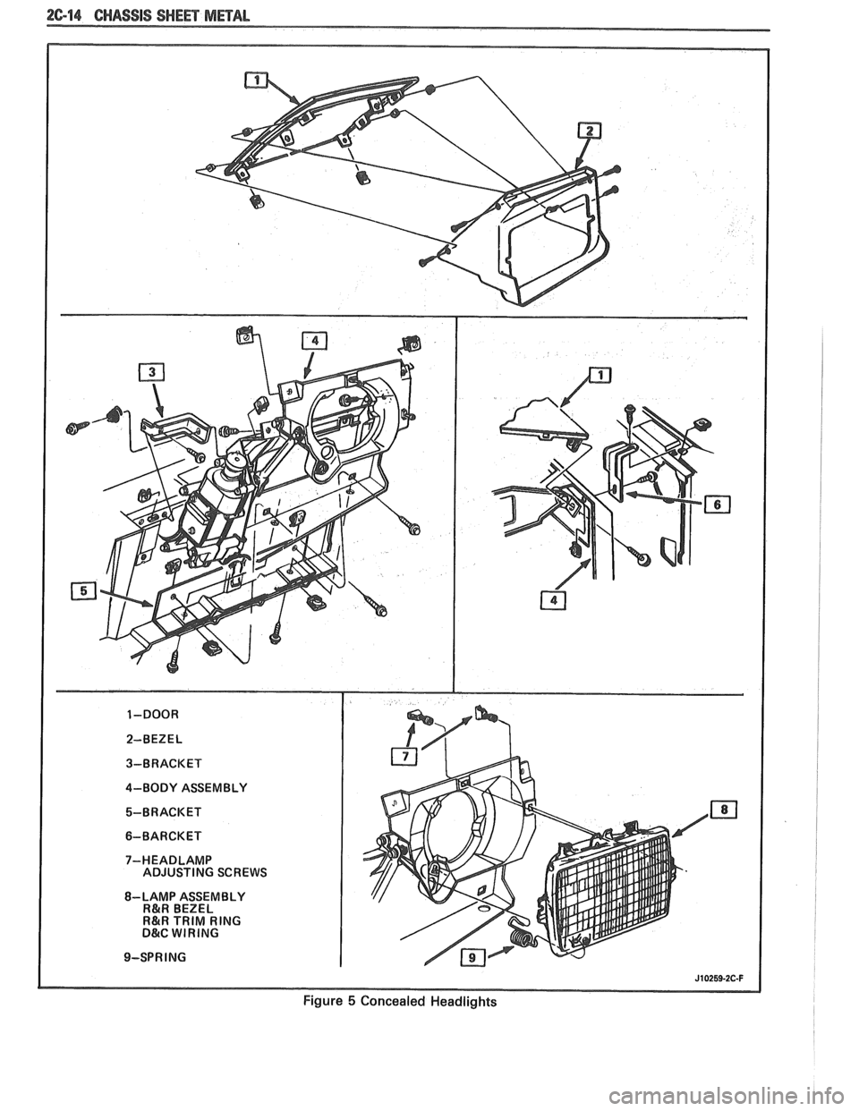
Figure 5 Concealed Headlights
Page 128 of 1825
STEERING, SUSPENSION, VIBES AND WHEELS DIAGNOSIS 3-3
Steering Wheel Kick-Back (Power)
Inspect
e Air in system
e Loose steering gear mounting
e Joints from column to steering gear loose or worn
e Tie rod ends loose
Worn or missing check valve
(800 series)
e Wheel bearings worn
e See "Too Much Play In Steering" for other
possible causes.
Steering Wheel Surges Or Jerks (Power)
Inspect
Hydraulic system - Make pressure test with gage
J 5176-D or
J 25323
e Sluggish steering gear valve
Loose pump drive belt
Cupped Tires
Inspect
Front-wheel or rear-wheel alignment
e Strut dampeners or shock absorbers weak
e Wheel bearing worn
e Excessive tire or wheel runout
e Worn ball joint
a Loose steering gear adjustment
POWER RECIRCULATING BALL
SEERING GEAR DIAGNOSIS
Hissing Noise
There is some noise in all power steering systems.
One of the most common is a hissing sound when the
steering wheel is turned and the car is not moving. This
noise will be most evident when turning the wheel
while the brakes are applied. There is no relationship
between this noise and steering performance. Do not
replace the valve unless the "hissing" noise is extremely
objectionable. A replacement valve will also have a
slight noise, and is not always a cure for the condition.
Check that the intermediate shaft joints are not loose.
Rattle or Chucking Noise
Inspect -
Pressure hose grounding out
e Tie rod ends loose
e Steering gear attachment loose
a Loose pitman shaft "over-center" adjustment.
A slight rattle may occur on turns because of
increased clearance off the "high point". This is
normal and clearance must not be reduced below
specified limits to eliminate this slight rattle.
Poor Return of Steering Wheel to Center
Front-wheel alignment
Wheel bearing worn
Tie rod end binding
Ball joint binding
Steering wheel rubbing against turn signal
housing
Steering gear adjustments
Tight or frozen intermediate steering shaft
Sticky or plugged spool valve
Momentary Increase in Effort Whsn Turning
Wheel Fast to Right or Left
Inspect
High internal leakage
Steering Wheel Surges or Jerks When Turning
With
Engine Running Especially During Parking
ln8pe~t
e Insufficient pump pressure
Sticky flow control valve
Excessive Wheel Kickback or Loose Steering
Air in system
Steering gear attachment loose
Tie rod ends loose
Wheel bearings worn
Steering gear flexible coupling loose on shaft or
rubber disc mounting nuts loose
Loose thrust bearing preload adjustment
Excessive "over-center" lash
Worn pressure port check valve
Hard Steering or Lack of Assist
(Especially During Parking)
-
Brakes applied while turning steering wheel
Intermediate shaft damaged or worn
e Sticky flow control valve
Insufficient pump pressure
Excessive internal pump leakage
Excessive internal steering gear leakage
STEERING LINKAGE DIAGNOSIS
Excessive Play or Looseness in Steering Systern
inspect
r, Worn upper ball joints
e Steering gear worm bearings loosely adjusted
Page 131 of 1825
3-6 STEERING, SUSPENSION, TIRES AND WHEELS DIAGNOSIS
Steering Wheel Loose
lnspect
Excessive clearance between holes in support or
housing and pivot pin diameters
e Damaged or missing anti-lash spring in spheres
e Upper bearing not seated in housing
e Upper bearing inner race seal missing
e Loose support screws
e Bearing preload spring missing or broken
Steering Wheel Loose (Every Other Tilt Position)
lnspect
e Loose fit between shoe and shoe pivot pin
e Shoe not free in slot
Steering Column Not Locking In Any Tilt
Position
lnspect
e Shoe seized on its pivot pin
e Shoe grooves may have burrs or dirt
e Shoe lock spring weak or broken
Steering Wheel Fails To Return To Top Tilt
Position
Inspect
e Pivot pins are bound up
e Wheel tilt spring is broken or weak
e Turn signal switch wires too tight
Noise When Tilting Column
Inspect
e Upper tilt bumpers worn
e Tilt spring rubbing in housing
TURN SIGNAL SWITCH
This diagnosis covers mechanical problems only
See Section
8A for turn signal switch electrical diagnosis.
Turn Signal Will Not Stay In Turn Position
lnspect
e Foreign material or loose parts impeding
movement of yoke
e Broken or missing detent or cancelling spring
s None of the above, replace switch
Turn Signal Will Not Cancel
lnspect
a Loose switch mounting screws
e Switch or anchor bosses broken
e Broken, missing or out of position detent, return
or cancelling spring
Worn cancelling cam
Turn Signal Difficult To Operate
0 Inspect
e Turn signal switch arm loose
e Yoke broken or distorted, replace switch
e Loose or misplaced springs
e Foreign parts andlor material
o Loose turn signal switch mounting screws
Turn Signal Will Not Indicate Lane Change
a Inspect
e Broken lane change pressure pad or spring
hanger
e Broken, missing or misplaced lane change spring
e Jammed base or wires
Hazard Switch Cannol: Be Turned Off
a Inspect
e Foreign material between hazard support
cancelling leg and yoke
e If no foreign material is found, replace turn signal
switch.
Hazard Switch Will Not Stay On or Difficult To
Turn Off
e Loose turn signal switch
a Interference with other components
e Foreign material interference
e None of the above, replace turn signal switch
No Turn Signal Lights
lnspect
e Electrical failure in chassis harness
e Inoperative turn signal flasher
e Loose chassis-to-column connector. Disconnect
column-to-chassis connector and connect new
turn signal switch to chassis and operate switch
by hand.
A. If car lights now operate normally, turn
signal switch is inoperative.
B. If
car lights do not operate, refer to Section 8A
for electrical diagnosis.
Turn Indicator Lights On, But Not Flashing
a Inspect
e Inoperative turn signal flasher
Loose chassis-to-column connection
Inoperative turn signal switch
Page 132 of 1825
STEERING, SUSPENSION, TIRES AND WHEELS DIAGNOSIS 3-7
e To determine if turn signal switch is inoperative,
substitute new turn signal switch into circuit and
operate switch by hand.
If the car's lights operate
normally, turn signal switch is inoperative.
Front Or Rear Turn Signal Lights Not Flashing
Inspect
s Burned-out or damaged turn signal bulb
e High resistance conection to ground at bulb
socket
s Loose chassis-to-column connector. Disconnect
column-to-chassis connector and connect new
turn signal switch into system and operate switch
by hand.
A. If turn signal lights are now on and flashing,
turn signal switch is inoperative.
B. If car lights do not operate, refer to Section
8A
for electrical diagnosis.
Turn Indicator Panel Lights
Inspect
Burned out bulbs or opens, grounds in the wiring
harness from the front turn signal bulb socket to the
indicator lights. Refer to Section
8A for electrical
diagnosis.
Stop Light Mot On When Turn Indicated
Inspect
s Loose column-to-chassis connection
e Disconnect the column-to-chassis connector and
connect the new turn signal switch into the
system and operate the switch by hand.
A. If the brake lights work when the switch is
in the turn position, the turn signal switch
is inoperative.
B. If the brake lights do not work, refer to Section
8A for electrical diagnosis.
Turn Signal Lights Flash Very Slowly
e Loose chassis-to-column connection
a Disconnect the column-to-chassis connector and
connect a new turn signal switch into the system
and operate the switch by hand.
A. If the lights flash at a normal rate, the turn
signal switch is inoperative.
B. If the Lights still flash very slowly, refer to
Section
8A for electrical diagnosis.
Hazard Signal Lights Will Not Flash - Turn
Signal Functions Normally
~"SPBC~
a Blown fuse
Inoperative hazard warning flasher
e Loose chassis-to-column connection
s Disconnect the column-to-chassis connector and
connect a new turn signal switch into the system,
then press in the hazard warning button and
watch the hazard warning lights.
A. If the lights now work normally, the turn
signal switch is inoperative.
B. If the lights do not flash, check the wiring
harness. Refer to Section
8A for electrical
diagnosis.
IGNITION SWITCH
Electrical System Will Not Function
Damaged ign~rion switch
e Ignition switch not adjusted properly
e Loose connector at the ignition switch
Switch Will Not Turn
Inspect
Damaged ignition switch
Switch Cannot Be Set Correctly
Inspect
Switch actuator rod deformed
e Sector to rack engaged in wrong tooth
KEY REMINDER
Figs. 1 through 11 ,
Weminder Continues To Operate With Key Out,
But Stops When Driver's Door Is Closed
e Chips, foreign material in lock cylinder bore
Sticky lock cylinder actuator tip
Damaged or broken reminder switch
Reminder Does Not Sound With Key Fully
Inserted In Lock Cylinder And The Driver's Door
Open
Inspect
1. Power not available to reminder. Refer to Sec-
tion
8A for electrical diagnosis.
2. Open in chassis wiring. Check by separating
chassis-to-column connector. Connect terminals
"E" and "F" female contacts on the chassis
connector (a bent paper clip will work). If the
reminder sounds, repair chassis wiring. If the
reminder does not sound, go to Step
A.
A. Connect a continuity meter (light) to the
male
"E" and "F" column connector
contacts. Push the key all the way into the
lock cylinder. If the light is on when the key
Page 133 of 1825
3-8 STEERING. SUSPENSION. TIRES AND WHEELS DIAGNOSIS
is in, and off when the key is out, the
function is normal. If the light is not on, the
fault is in the column. Go to Step B.
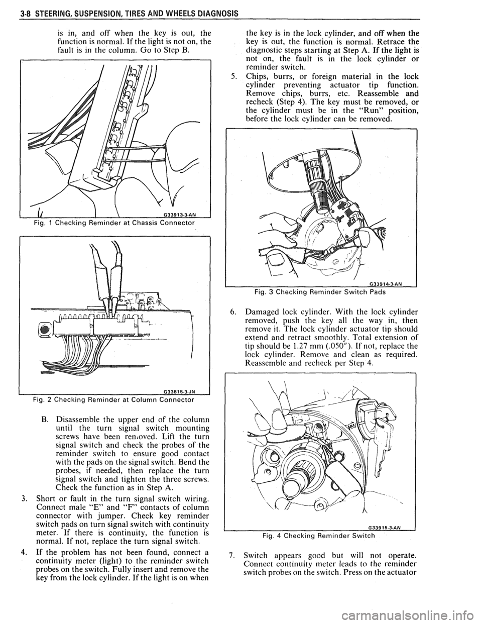
Fig. 1 Checking Reminder at Chassis Connector
Fig.
2 Checking Reminder at Column Connector
B. Disassemble the upper end of the column
until the turn
signal switch mounting
screws have been
removed. Lift the turn
signal switch and check the probes of the
reminder switch to ensure good contact
with the pads on the signal switch. Bend the
probes, if needed, then replace the turn
signal switch and tighten the three screws.
Check the function as in Step
A.
3. Short or fault in the turn signal switch wiring.
Connect male
"E" and "F" contacts of column
connector with jumper. Check key reminder
switch pads on turn signal switch with continuity
meter. If there is continuity, the function is
normal. If not, replace the turn signal switch. the
key is in the lock cylinder, and off when the
key is out, the function is normal. Retrace the
diagnostic steps starting at Step
A. If the light is
not on, the fault is in the lock cylinder or
reminder switch.
Chips, burrs, or foreign material in the lock
cylinder preventing actuator tip function.
Remove chips, burrs, etc. Reassemble and
recheck (Step 4). The key must be removed, or
the cylinder must be in the "Run" position,
before the lock cylinder can be removed.
Fig. 3 Checking Reminder Switch Pads
6. Damaged lock cylinder. With the lock cylinder
removed, push the key all the way in, then
remove it. The lock cylinder actuator tip should
extend and retract smoothly. Total extension of
tip should be
1.27 mm (.05OU). If not, replace the
lock cylinder. Remove and clean as required.
Reassemble
and recheck per Step 4.
Fig. 4 Checking Reminder Switch
4.. If the problem has not been found, connect a 7. switch appears good but will not operate, continuity meter (light) to the reminder switch
Connect continuity meter leads to the reminder
probes on the switch. Fully insert and remove the
switch probes on the switch. Press on the actuator
key from the lock cylinder. If the light is on when