MISCELLANEOUS ACCESSORIES 96-4
SCELLANEOUS ACCESSOR
General Description ................................. 9G-1
Rally Gages .................................................. 9G- 1
Tachometer ................................................. 9G- 1
Trip Odometer
............................................. 9G- 1
Electric Rear Window Defogger ................. 9G-2
Power Remote Control Rearview
Mirror ........................................................ 9G-2
Diagnosis .................................................... 9G-2
Rally Gages ............................................... 9G-2
Tachometer .................................... .... .... 9G-2
Electric Rear Window Defogger ................. 9G-2
Power Remote Control Rearview
Mirror ........................................................ 96-2
Dash and Console Mounted
Accessory Switches
................................. 9G-4
General Description .................................. 9G-4
Electronic Glare Control Mirror ................. 9G-4
On-Car Service ............................................. 9G-4
Rally Gages, Tach ....................................... 96-4.
Rear Window Defogger ............................ 96-4.
Power Remote Control Mirror .................... 9G-4
GENERAL BESCRIP"T0N
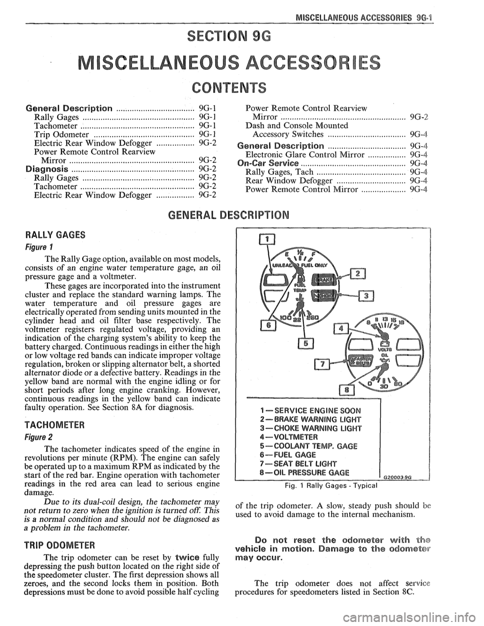
RALLY GAGES
Figure I
The Rally Gage option, available on most models,
consists of an engine water temperature gage, an oil
pressure gage and a voltmeter.
These gages are incorporated into the instrument
cluster and replace the standard warning lamps. The
water temperature and oil pressure gages are
electrically operated from sending units mounted in the
cylinder head and oil filter base respectively. The
voltmeter registers regulated voltage, providing an
indication of the charging system's ability to keep the
battery charged. Continuous readings in either the high
or low voltage red bands can indicate improper voltage
regulation, broken or slipping alternator belt,
a shorted
alternator diode
or a defective battery. Readings in the
yellow band are normal with the engine idling or for
short periods after long engine cranking. However,
continuous readings in the yellow band can indicate
faulty operation. See Section
8A for diagnosis.
TACHOMETER
Figure 2
The tachometer indicates speed of the engine in
revolutions per minute (RPM). The engine can safely
be operated up to a maximum RPM as indicated by the
start of the red bar. Engine operation with tachometer
readings in the red area can lead to serious engine
damage.
Due to its dual-coil design, the tachometer may
not return to zero when the ignition
is turned oft: This
is
a normal condition and should not be diagnosed as
a problem in the tachometer.
TRIP ODOMETER
The trip odometer can be reset by twice fully
depressing the push button located on the right side of
the speedometer cluster. The first depression shows all
zeroes, and the second locks them in position. Both
depressions must be done to avoid possible half cycling
I -SERVICE ENGINE SOON
2-BRAKE WARNING LIGHT
3-CHOKE WARNING LIGHT
4-VOLTMETER
5-COOUNT TEMP. GAGE
6-FUEL GAGE
7-SEAT BELT LIGHT
8-OIL PRESSURE GAGE G20003 9G
Fig. 1 Rally Gages - Typical
of the trip odometer. A slow, steady push should be
used to avoid damage to the internal mechanism.
Do not reset the odometer with the
vehicle in motion. Damage to the odometer
may occur.
The trip odometer does not affect service
procedures for speedometers listed in Section
8C.
REAR QUARTERS - F STYLE 8H-1
SECTION 6H
REAR QUARTERS
NOTICE: The anti-theft label found on some major sheet metal, engines, and transmissions must be masked
prior to painting, rustproofing, undercoating, etc. The mask
must be removed following the above operations.
Failure to keep the label clean and readable may result in liability for violation of Federal Vehicle Theft Prevention
Standard, and subject the vehicle owner to possible suspicion that the part was stolen.
CONTENTS
Quarter Trim .................................................... 6H- 1
Lower Trim Finishing Panel ....................... 6H- 1
Body Lock Pillar Trim Finishing
Panel
., ....................................................... 6H- 1
Upper Trim Finishing Panel Insert ............. 6H- 1
....................................................... Speakers 6H- 1
Lift Window Upper Finishing
Molding
..................................................... 6H-2
....................... Upper Trim Finishing Panel 6H-2
QUARTER TRlM
QUARTER LOWER TRlM FINISHING PANEL
Removal and Installation (Fig. 1)
Remove body lock pillar finishing panel (Fig. 3).
Remove rear
seatback lock striker.
Remove retaining screw in rearward area of
quarter lower trim panel.
Remove rear screws from sill plate and carpet
retainer (Fig.
2).
Grasp quarter lower trim panel with hand; then
pull forward and down to disengage from
pinchweld flange at weatherstrip and quarter
upper trim finishing panel.
Remove seat belt through slot in trim panel.
Remove quarter lower trim finishing panel from
car by lifting up on rear portion of sill plate and
carpet retainer; then pull quarter trim rearward.
To install, place panel retaining slots under
quarter upper trim panel and apply upward
pressure to secure.
Position panel assembly to body. Thread lap and
shoulder belt through respective slots in panel.
Install attaching screws to secure panel to body.
Replace all previously removed components.
BODY LOCK PILLAR TRlM FINISHING PANEL
Removal and lnstallation (Fig. 3)
1. Remove trim panel attaching screws.
2. Using trim removing tool J-24595B, BT-7323A
or equivalent, carefully disengage nylon fasteners
that retain body lock pillar panel to quarter upper
trim finishing panel.
3. To install, reverse removal procedures. Spare
Tire Cover Trim Finishing
Panel
........................................................ 6H-3
Rear Stowage Compartment Box
Assembly
................................................... 6H-4
Luggage Shade Cover Assembly
................. 6H-4
Exterior Moldings
........................................... 6H-6
Fuel Tank Filler Door and Pocket
Assembly
....................................................... 6H-7
Spoiler Extension
............................ .. ........... 6H-7
QUARTER UPPER TRlM FINISHING PANEL
INSERT
Removal and Installation (Fig. 4)
1. Remove coat hook.
2. Grasp panel insert with hand and pull upward to
disengage retainers from cutout slots in quarter
upper trim finishing panel (Fig. 4).
3. To install, reverse removal procedures.
REAR QUARTER SPEAKERS
The rear quarter speakers are installed to a
speaker retainer. The retainer and speaker are then
attached to the quarter inner panel by screws.
Standard Speakers
Remove or Disconnect
1. Quarter upper trim finishing panel insert
2. Screws securing speaker retainer
3. Disconnect electrical
connector from speaker
4. Speaker
Install or Connect
1. Speaker to body
2. Electrical connector
3. Screws securing speaker to retainer
4. Quarter upper trim finishing panel insert
Subwoofer Speakers (2FS/FW/FX Styles)
Remove or Disconnect (Fig. 5)
1.
Quarter upper trim finishing panel insert (Fig. 4)
2. Body lock pillar trim finishing panel (Fig. 3)
3. Two rear screws from carpet retainer (Fig.
2)
4.
Quarter lower trim finishing panel