1988 PONTIAC FIERO radio controls
[x] Cancel search: radio controlsPage 36 of 1825
HEATING AND VENTILATION 1.4-1 3
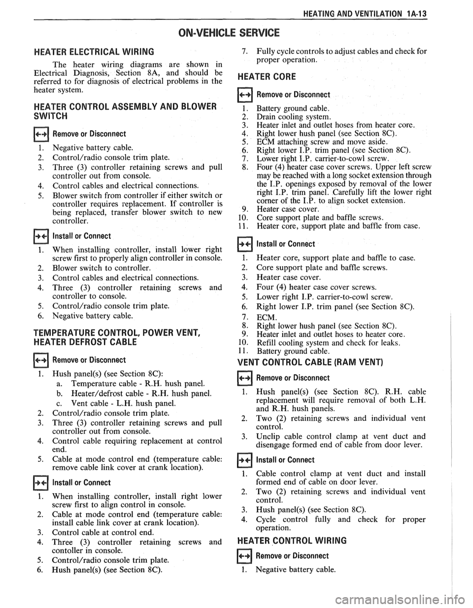
ON-VEHICLE SERVICE
HEATER ELECTRICAL WIRING
The heater wiring diagrams are shown in
Electrical Diagnosis, Section
8A, and should be
referred to for diagnosis of electrical problems in the
heater system.
HEATER CONTROL ASSEMBLY AND BLOWER
SWITCH
Remove or Disconnect
1. Negative battery cable.
2.
Control/radio console trim plate.
3. Three
(3) controller retaining screws and pull
controller out from console.
4. Control cables and electrical connections.
5. Blower switch from controller if either switch or
controller requires replacement. If controller is
being replaced, transfer blower switch to new
controller.
Install or Connect
1. When installing controller, install lower right
screw first to properly align controller in console.
2. Blower switch to controller.
3. Control cables and electrical connections.
4. Three (3) controller retaining screws and
controller to console.
5. Control/radio console trim plate.
6. Negative battery cable.
TEMPERATURE CONTROL, POWER VENT,
HEATER DEFROST CABLE
Remove or Disconnect
1. Hush panel(s) (see Section 8C):
a. Temperature
cable - R.H. hush panel.
b.
Heateddefrost cable - R.H. hush panel.
c. Vent
cable
- L.H. hush panel.
2.
Control/radio console trim plate.
3. Three (3) controller retaining screws and pull
controller out from console.
4. Control cable requiring replacement at control
end.
5. Cable at mode control end (temperature cable:
remove cable link cover at crank location).
Install or Connect
1. When installing controller, install right lower
screw first to align control in console.
2. Cable
at mode control end (temperature cable:
install cable link cover at crank location).
3. Control cable at control end.
4. Three (3) controller retaining screws and
contoller in console.
5. Control/radio console trim plate.
6. Hush panel(s) (see Section 8C).
7. Fully cycle controls to adjust cables and check for
proper operation.
HEATER CORE
Remove or Disconnect
Battery ground cable.
Drain cooling system.
Heater inlet and outlet hoses from heater core.
Right lower hush panel (see Section
8C).
ECM attaching screw and move aside.
Right lower I.P. trim panel (see Section
8C).
Lower right I.P. carrier-to-cowl screw.
Four (4) heater case cover screws. Upper left screw
may be reached with a long socket extension through
the I.P. openings exposed by removal of the lower
right I.P. trim panel. Carefully lift the lower right
corner of the I.P. to align socket extension.
Heater case cover.
Core support plate and baffle screws.
Heater core, support plate and baffle from case.
Install or Connect
1. Heater core, support plate and baffle to case.
2. Core support
plate and baffle screws.
3. Heater case cover.
4. Four (4) heater case cover screws.
5. Lower right I.P. carrier-to-cowl screw.
6. Right lower I.P. trim panel (see Section 8C).
7. ECM.
8. Right lower hush panel (see Section
8C).
9. Heater inlet and outlet hoses to heater core.
10. Refill cooling system and check for leaks.
11. Battery ground cable.
VENT CONTROL CABLE (RAM VENT)
Remove or Disconnect 1
1. Hush panel(s) (see Section 8C). R.H. cable
replacement will require removal of both L.H.
and R.H. hush panels.
2. Two
(2) retaining screws and individual vent
control.
3. Unclip
cable control clamp at vent duct and
disengage formed end of cable from door lever.
1 Install or Connect
1. Cable control clamp at vent duct and install
formed end of cable on door lever.
2, Two (2) retaining screws and individual vent
control.
3. Hush
panel@) (see Section 8C).
4. Cycle
control fully and check for proper
operation.
HEATER CONTROL WIRING I
Remove or Disconnect
1. Negative battery cable.
Page 1166 of 1825
CONTENTS
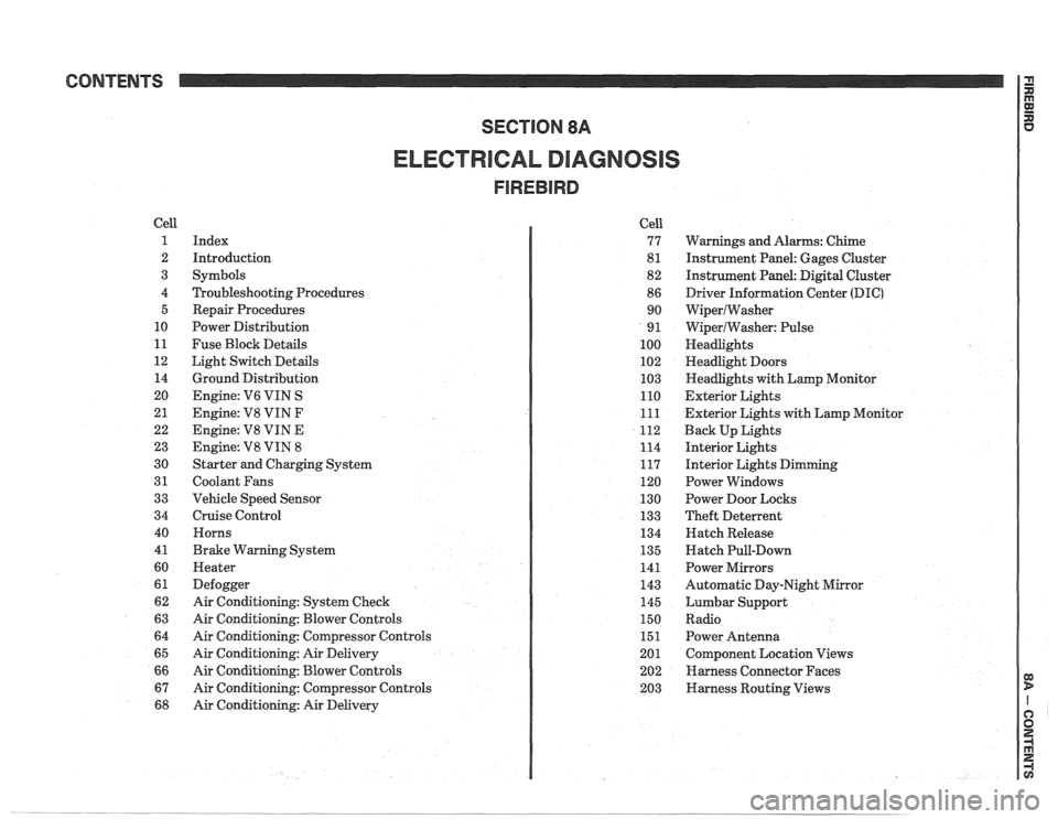
ELECTRICAL DIAGNOSIS
Cell
1
2
3
4 5
10
11
12 14
20
21
22
23
30
31
33
34
40
4
1
60
61
62
63
64
65
66
67
68
Index
Introduction
Symbols
Troubleshooting Procedures Repair Procedures
Power Distribution
Fuse Block Details
Light Switch Details
Ground Distribution
Engine:
V6 VIN S
Engine: V8 VIN
F
Engine: V8 VIN E
Engine:
V8 VIN 8
Starter and Charging System
Coolant Fans
Vehicle Speed Sensor
Cruise Control Horns
Brake Warning System
Heater
Defogger
Air Conditioning: System Check
Air Conditioning: Blower Controls
Air Conditioning: Compressor Controls
Air Conditioning: Air Delivery
Air Conditioning: Blower Controls
Air Conditioning: Compressor Controls
Air Conditioning: Air Delivery Cell
77
8
1
82
86 90
9
1
100
102
103
110
111
112
114
117
120
130
133
134
135
141
143
145
150
151
201 202
203
Warnings and Alarms: Chime
Instrument Panel: Gages Cluster
Instrument Panel:
Digital Cluster
Driver Information Center
(DIC)
WiperlWasher
WiperlWasher: Pulse
Headlights
Headlight Doors
Headlights with Lamp Monitor
Exterior Lights
Exterior Lights with Lamp Monitor
Back Up Lights
Interior Lights
Interior Lights Dimming
Power Windows
Power Door Locks
Theft Deterrent
Hatch Release
Hatch Pull-Down
Power Mirrors
Automatic Day-Night Mirror
Lumbar Support
Radio Power Antenna
Component Location Views
Harness Connector Faces
Harness Routing Views
Page 1167 of 1825
Page
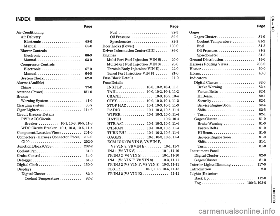
Air Conditioning
Air Delivery
Electronic
.................... 68-0
Manual
....................... 65-0
Blower Controls
Electronic
.................... 66-0
Manual
....................... 63-0
Compressor Controls Electronic
.................... 67-0
Manual
....................... 64-0
................... System Check 62-0
Alarms (Audible)
Chime
......................... 77-0
Antenna(Power) ................... 151-0
Brakes
................. Warning System 41-0
................... Charging system 30-7
...................... Cigar Lighter 114-0
Circuit Breaker Details
PWR ACC Circuit
.......... Breaker 10.1.10.3.10.5.1 1.3
WDO Circuit Breaker
10.1. 10.3. 10.5. 11-4
.......... Component Location Views 201-0
Connectors (Harness Connector Faces) 202-0
el00 .......................... 202-0
............... Junction Block ((2238) 202-2
Coolant Fan
....................... 31-0
Cruise Control
..................... 34-0
Defogger
......................... 61-0
Digital Clock
...................... 150-0
Displays Digital Cluster
.................. 82-0
Coolant Temperature
........... 82-2
Page
......................... Fuel 82-3
................... Oil Pressure 82-2
.................. Speedometer 82-3
................. Door Locks (Power) 130-0
...... Driver Information Center (DIC) 86-0
Engines
... Multi-Port Fuel Injection (VIN S) 20-0
.... Multi-Port Fuel Injection (VIN 8) 23-0
.... Throttle
Body Injection (VIN E) 22-0
...... Tuned
Port Injection (VIN F) 21-0
................. Fuse Block Details 11-0
Fuse Details
........... INST LP 10.0.10.2.10.4.1 1.1
.............. TAIL 10.0.10.2.10.4.1 1.2
................ CRANK 10.0.10.2.1 0.4
.............. CTSY 10~0.10.2.10.4.1 1.2
......... STOP HAZ 10.1.10.3.10.5.1 1.3
............ RADIO 10.1.10.3.10.5.1 1.4
............ WIPER 10.1.10.3.10.5.1 1.4
.................... HATCH 10.2.1 0.4
........... HTR AlC 10.1.10.3.10.5.1 1.4
........... CIH.FAN 10.1.10.3.10.5.1 1.4
......... TURN BIU 10.1.10.3.10.5.1 1.4
............ GAGES 10.1.10.3.10.5.1 1.4
ECM-IGN
(V6 VIN S. V8 VIN F.
........ V8 VIN 8. V8 VIN E) 10.1.1 1.7
............ INJ 1 (V6 VIN S) 10.1.1 1.10
......... FPIINJ 2 (V6 VIN S) 10.1.1 1.10
... INJ 1 (V8 VIN F. V8 VIN 8) 10.3.1 1.11
FPIINJ 2 (V8 VIN F. V8 VIN 8) 10.3.1 1.11
............ CLSTR 10.1.10.3.10.5.1 1.13
............. FPIINJ 2 (V8 VIN E) 11-12
Page
Gages
................... Gages Cluster 81-0
........... Coolant Temperature 81-2
......................... Fuel 81-3
................... Oil Pressure 81-2
.................. Speedometer 81-3
................ Ground Distribution 14-0
Harness Routing Views
............. 203-0
........................... Heater 60-0
............................ Horns 40-0
Indicators
.................. Digital Cluster 82-0
................ Brake Warning 82-4
.................. Fasten Belts 82-1
...................... Hi Beam 82-1
...................... Security 82-1
............ Service Engine Soon 82-4
......................... Shift 82-5
......................... Turn 82-1
................... Gages Cluster 81-0
................ Brake Warning 81-0
.................. Fasten Belts 81-0
...................... Hi Beam 81-0
............ Service Engine Soon 81-0
......................... Shift 81-1
......................... Turn 81-0
Instrument Panel
Digital Cluster
.................. 82-0
Gages Cluster
................... 81-0
............ Interior Lights Dimming 117-0
...................... Introduction 2-0
Lights (Exterior)
........................ Back Up 112-0
...................... Fog 100.3,10 3.0
Page 1547 of 1825
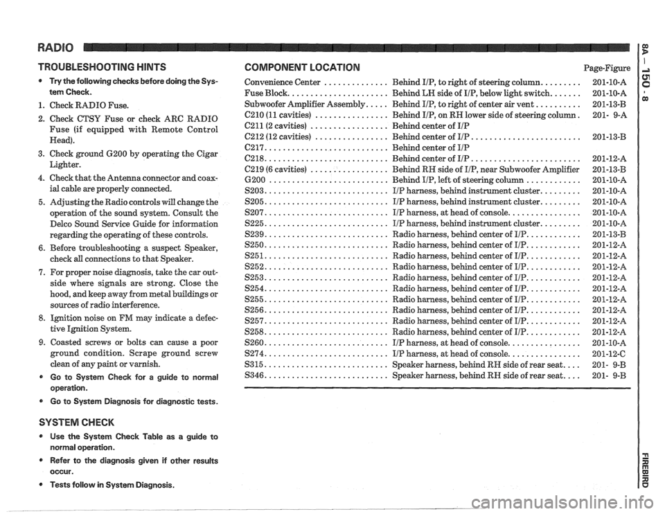
TROUBLESHOOTING HINTS
Try the following checks before doing the Sys-
tem Check
.
1 . Check RADIO Fuse .
2 . Check CTSU Fuse or check ARC RADIO
Fuse (if equipped with Remote Control
Head)
.
3 . Check ground 6200 by operating the Cigar
Lighter
.
4 . Check that the Antenna connector and coax-
ial cable are properly connected
.
5 . Adjusting the Radio controls will change the
operation of the sound system
. Consult the
Delco Sound Service Guide for information
regarding the operating of these controls
.
6 . Before troubleshooting a suspect Speaker,
cheek
all connections to that Speaker .
7 . For proper noise diagnosis. take the car out-
side where
signals are strong . Close the
hood. and keep away from metal buildings or
sources of radio interference
.
8 . Ignition noise on FM may indicate a defec-
tive Ignition System
.
9 . Coasted screws or bolts can cause a poor
ground condition
. Scrape ground screw
clean of any paint or varnish
.
Go to System Check for a guide to normal
operation
.
r Go to System Diagnosis for diagnostic tests .
SYSTEM CHECK
* Use the System Check Table as a guide to
normal operation
.
Refer to the diagnosis given if other results
occur
.
COMPONENT LOCATION Page-Figure
......... .............. Convenience Center Behind IIP. to right of steering column 201-10-A
....... Fuse Block ...................... Behind LH side of IIP. below light switch 201-10-A
.......... Subwoofer Amplifier Assembly ..... Behind IIP. to right of center air vent
201-13-B
. C210 (11 cavities) ................ Behind IIP. on RH lower side of steering column 201- 9-A
C211(2 cavities) ................. Behind center of IIP
........................ C212 (12 cavities) ................ Behind center of IIP 201-13-B
C217 ........................... Behind center of IIP
........................ C218 ........................... Behind center of IIP 201-12-A
C219 (6 cavities)
................. Behind RH side of IIP. near Subwoofer Amplifier 201-13-B
............ 6200 .......................... Behind IIP. left of steering column 201-10-A
......... $203 ........................... IIP harness. behind instrument cluster 201-10-A
......... $205 ........................... IIP harness. behind instrument cluster 201-10-A
................ $207 ........................... I/P harness. at head of console 201-10-A
......... S225 ........................... IIP harness. behind instrument cluster 201-10-A
............ $239 ........................... Radio harness. behind center of IIP 201-13-B
............ S250 ........................... Radio harness. behind center of I/P 201-12-A
............ $251 ........................... Radio harness. behind center of IIP 201-12-A
............ S252 ........................... Radio harness. behind center of IIP 201-12-A
............ S253 ........................... Radio harness. behind center of l[/P 201-12-8
............ $254 ........................... Radio harness. behind center of IIP 201-12-A
............ S255 ........................... Radio harness. behind center of I/P 201-12-A
............ ,9256 ........................... Radio harness. behind center of IIP 201-12-A
............ S257 ........................... Radio harness. behind center of IIP 201-12-A
............ S258 ........................... Radio harness. behind center of IIP 201-12-A
$260 ........................... IIP harness. at head of console ................ 201-10-A
................ S274 ........................... IIP harness. at head of console 201-12-C
$315 ........................... Speaker harness. behind RH side of rear seat .... 201- 9-B
.... $346 ........................... Speaker harness. behind RH side of rear seat 201- 9-B
Tests follow in System Diagnosis .
Page 1548 of 1825
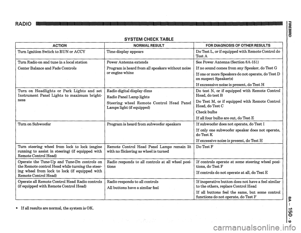
RADIO
SYSTEM CHECK TABLE
ACTION NORMAL RESULT FOR DlAGNOSlS OF OTHER RESULTS
Turn Ignition Switch to RUN or ACCU Time display appears Do
Test L, or if equipped with Remote Control do
Test A
Turn Radio on and tune
in a local station Power Antenna extends See
Power Antenna (Section 8A-151)
Center Balance and Fade Controls Program
is heard from all speakers without noise If
no sound comes from any Speaker, do Test G
or engine whine
If one or more Speakers do not operate, do Test D
on suspect
Speaker(s)
If excesssive noise is present, do Test H
Turn on Headlights or Park Lights and set
Radio digital display dims Do
test
N, or if equipped with Remote Control
Instrument Panel Lights to maximum
bright- Radio Panel Lamp khts Head, do test B
Lamps light (if equipped) Head,
do Test C
If all results are normal, the system is OK.
Page 1556 of 1825
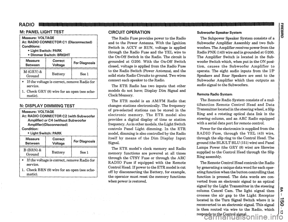
M: WNEL LIGHT TEST GlRGUlT OPERATION Subwoofer Speaker System
TOR 61 (Disconnected)
If the voltage is correct, remove Radio for
N: DISPLAY DIMMING TEST
TOW 62 (with Subwoofer
The Radio Fuse provides power to the Radio
and to the Power Antenna. With the Ignition
Switch in ACCY or RUN, voltage is applied
through the Radio Fuse and the
UEL wire to
the On-Off Switch in the Radio. The circuit is
grounded at 6200. With the On-Off Switch
closed, voltage is applied from the Radio Fuse
to the Radio Switch (Power Antenna), and the
solid state Radio Circuits to ground. Two wires
connect each speaker to the Radio.
The ETR Radio has two inputs that other
models do not have; Display Dim Signal and
ClocklMemory.
The ETR model is an AMIFM Radio that
changes stations electronically. The frequency
of pre-selected stations can be stored
in the
electronic memory. The ETR model also
provides a digital display of time or station
frequency. As in other models, the Light Switch
controls Panel Light dimming. In the
ETR
model, g is also controlled by the Radio
itself by means of the Dim Display Input
Signal.
The ETR model's clock memory and Radio
memory functions are powered at all times
through the CTSY Fuse or through the ARC
RADIO Fuse if equipped with the Remote
Control Head. If power to the ETR model is cut
off by disconnecting the Battery, for example,
the operator must reset the memory functions
when power is restored. The
Subpower Speaker
System consists of a
Subwoofer Amplifier Assembly and two Sub-
woofers. The Amplifier receives power from the
Radio PNK
(143) wire and is grounded at 6200.
The Amplifier Switch is located in the
Sub-
woofer Switch which, when put in the ON posi-
tion, causes the Subwoofer Amplifier to
operate. The eight audio inputs from the
I/P
Speakers and Rear Speakers are sent to the
Subwoofer Amplifier which then outputs an
audio signal to the Subwoofers.
Remote Radio System
The Remote Radio System consists of a mul-
tifunction Remote Control
Head and Data
Transmitter located in the steering wheel, a Slip
Ring and a rotating optical data link in the
steering
colurnn, and an ARC Radio equipped
with a serial data port for remote control.
Power for the electronics is supplied from the
RADIO Fuse, through the
YEL (43) wire,
through the slip ring to the Control Head. The
ground (the
BLKLT BLU (15 1) wire) and Pand
Larnps Power (the GRY (8) wire) are Likewise
supplied to the Control Head through the Slip
Ring assembly.
The Remote Control Head controls the Radio
by generating a unique data word for each oper-
ating function when the button controlling that
function is pressed. The data words are con-
verted from an electronic signal to an optical
signal by the Light Transmitter in the steering
column Cancel Cam. The light signal then
crosses the air gap to the Light Receptor
located in the
Turn Signal Switch where it is
reconverted to
an electronic signal. This signal
is then routed via wire to the Radio, which
responds to the Control signal.
Page 1650 of 1825
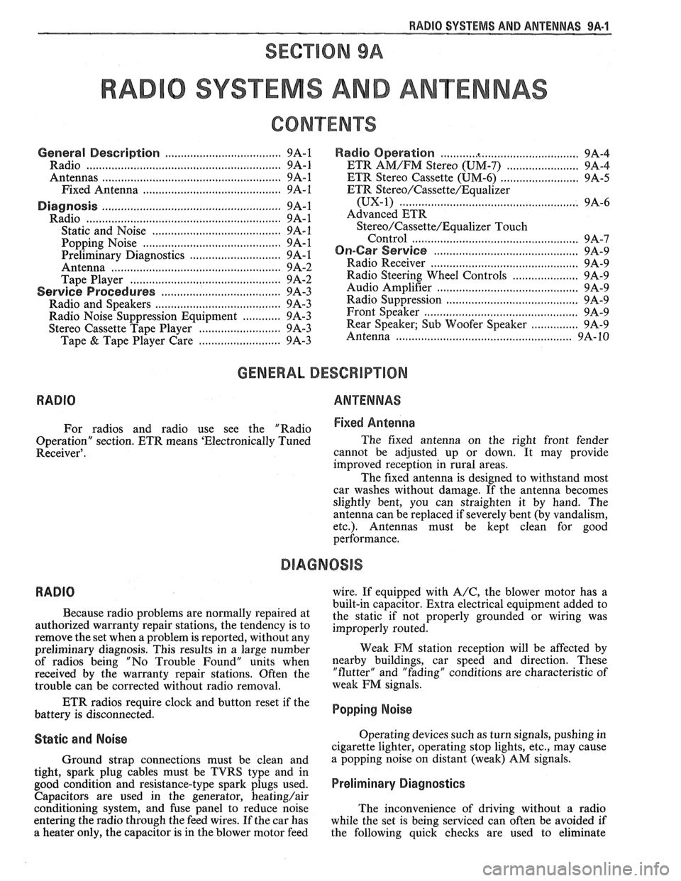
RADIO SYSTEMS AND ANTENNAS 9A-1
SECTION 9A
0 SYSTEMS AND ANTENNAS
CONTENTS
............................................. General Description .................................... 9A-1 Radio Operation 9A-4
Radio
............................................................ 9A-1 ETR AM/FM Stereo (UM-7) ....................... 9A-4
Antennas
........................................................ 9A- 1 ETR Stereo Cassette (UM-6) ......................... 9A-5
Fixed Antenna
.......................................... 9A- 1 ETR Stereo/Cassette/Eaualizer
Diagnosis ........................................................
Radio ....................... .. ................................
Static and Noise .................................... .....
........................................ Popping Noise
Preliminary Diagnostics
.............................
Antenna ................................. .. ................
Tape Player .................. .... .......................
Service Procedures ....................................
Radio and Speakers ........................... .............
Radio Noise Suppression Equipment ............
Stereo Cassette Tape Player ..........................
Tape & Tape Player Care ........................
(UX-1) ..................................................... 9A-6
Advanced ETR
Stereo/Cassette/Equalizer Touch
Control
.................................... ... .............. 9A-7
On-Car Service .............................................. 9A-9
Radio Receiver
............................................ 9A-9
Radio Steering Wheel Controls
..................... 9A-9
Audio Amplifier
........................................... 9A-9
Radio Suppression
..................................... 9A-9
Front Speaker
................................................. 9A-9
............... Rear Speaker; Sub Woofer Speaker
9A-9
Antenna
..................... .. ............................. 9A- 10
GENERAL DESCRIPUION
RADIO ANTENNAS
For radios and radio use see the "Radio Fixed Antenna
Operation" section. ETR means 'Electronically Tuned The
fixed antenna on the right front fender
Receiver'. cannot be adjusted up or down. It may provide
improved reception in rural areas.
- The fixed antenna is designed to withstand most
car washes without damage. If the antenna becomes
slightly bent, you can straighten it by hand. The
antenna can be replaced if severely bent (by vandalism,
etc.). Antennas must be kept clean for good
performance.
RADIO
Because radio problems are normally repaired at
authorized warranty repair stations, the tendency is to
remove the set when a problem is reported, without any
preliminary diagnosis. This results in a large number
of radios being "No Trouble Found" units when
received by the warranty repair stations. Often the
trouble can be corrected without radio removal. wire.
If equipped with
A/C, the blower motor has a
built-in capacitor. Extra electrical equipment added to
the static if not properly grounded or wiring was
improperly routed.
Weak
FM station reception will be affected by
nearby buildings, car speed and direction. These
"flutter" and "fading" conditions are characteristic of
weak FM signals.
ETR radios require clock and button reset if the
battery is disconnected.
Popping Noise
Static and Noise Operating devices such as turn signals, pushing in
cigarette lighter, operating stop lights, etc., may cause
Ground strap connections must be clean and
a popping noise on distant (weak) AM signals.
tight, spark plug cables must be TVRS type and in
good condition and resistance-type spark plugs used.
Preliminary Diagnostics
Capacitors are used in the generator, heating/air
conditioning system, and fuse panel to reduce noise
The inconvenience of driving without a radio
entering the radio through the feed wires. If the car has
while the set is being serviced can often be avoided if
a heater only, the capacitor is in the blower motor feed
the following quick checks are used to eliminate
Page 1654 of 1825
RADIO SYSEEMS AWlD ANTENNAS 9A-5
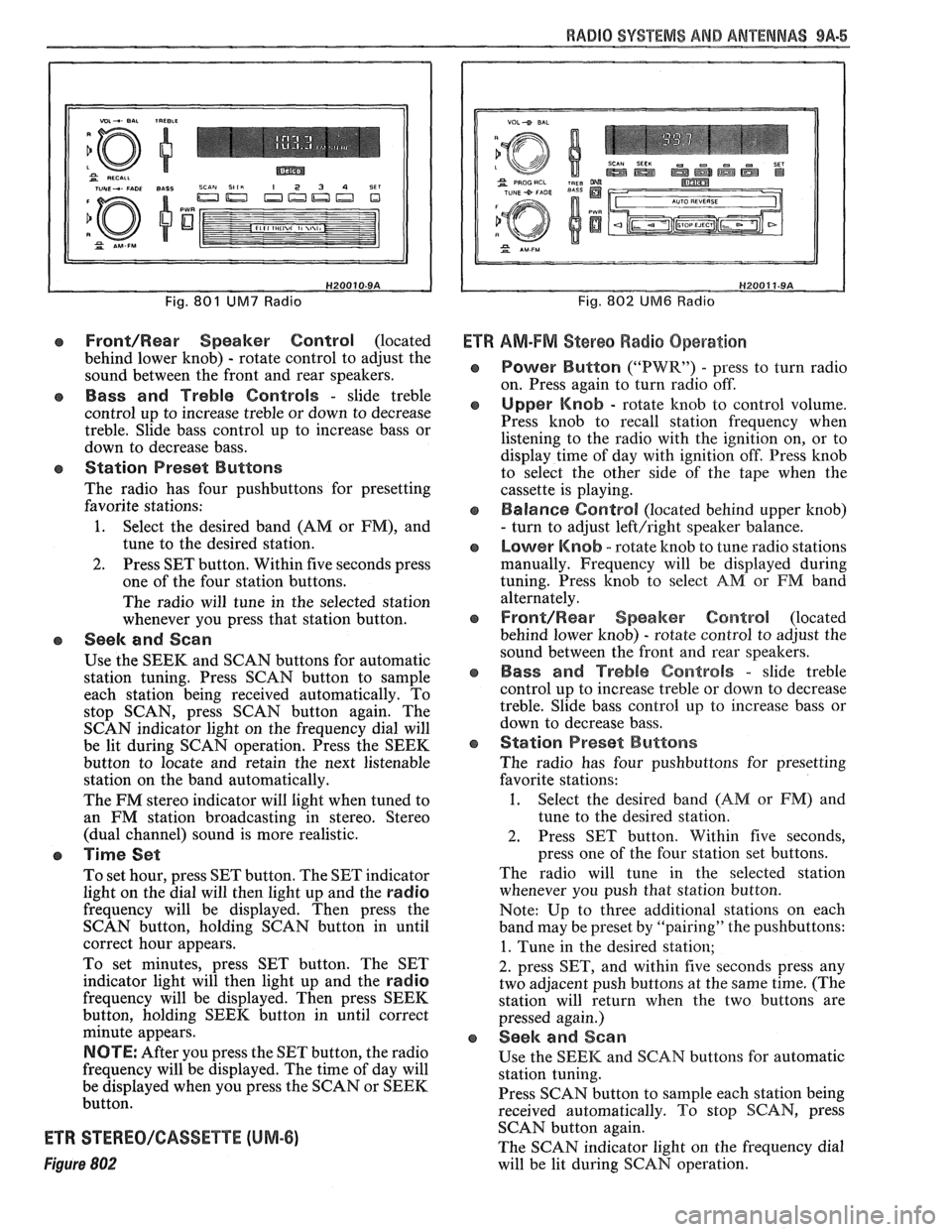
Fig. 801 UM7 Radio
Front/Rear Speaker Control (located
behind lower knob)
- rotate control to adjust the
sound between the front and rear speakers.
e Bass and Treble Controls - slide treble
control up to increase treble or down to decrease
treble. Slide bass control up to increase bass or
down to decrease bass.
e Station Preset Buttons
The radio has four pushbuttons for presetting
favorite stations:
1. Select the desired band (AM or FM), and
tune to the desired station.
2. Press SET button. Within five seconds press
one of the four station buttons.
The radio will tune in the selected station
whenever you press that station button.
e Seek and Scan
Use the SEEK and SCAN buttons for automatic
station tuning. Press SCAN button to sample
each station being received automatically. To
stop SCAN, press SCAN button again. The
SCAN indicator light on the frequency dial will
be lit during SCAN operation. Press the SEEK
button to locate and retain the next listenable
station on the band automatically.
The FM stereo indicator will light when tuned to
an FM station broadcasting in stereo. Stereo
(dual channel) sound is more realistic.
a Time Set
To set hour, press SET button. The SET indicator
light on the dial will then light up and the
radio
frequency will be displayed. Then press the
SCAN button, holding SCAN button in until
correct hour appears.
To set minutes, press SET button. The SET
indicator light will then light up and the
radio
frequency will be displayed. Then press SEEK
button, holding SEEK button in until correct
minute appears.
NOTE: After you press the SET button, the radio
frequency will be displayed. The time of day will
be displayed when you press the SCAN or SEEK
button.
ETR STEREO/GASSETTE (UM-6)
Figure 802
Fig. 802 UM6 Radio
Ef R AM-FM Stereo Radio Operation
Power Button ("PWR") - press to turn radio
on. Press again to turn radio off.
Upper Knob - rotate knob to control volume.
Press knob to recall station frequency when
listening to the radio with the ignition on, or to
display time of day with ignition off. Press knob
to select the other side of the tape when the
cassette is playing.
Balance Control (located behind upper knob)
- turn to adjust left/right speaker balance.
Lower Knob - rotate knob to tune radio stations
manually. Frequency will be displayed during
tuning. Press knob to select
AM or FM band
alternately.
Front/Rearr Speaker Control (located
behind lower knob)
- rotate control to adjust the
sound between the front and rear speakers.
Bass and Treble Controls - slide treble
control up to increase treble or down to decrease
treble. Slide bass control
up to increase bass or
down to decrease bass.
Station Preset Buttons
The radio has four pushbuttons for presetting
favorite stations:
1. Select the desired band (AM or FM) and
tune to the desired station.
2. Press SET button. Within five seconds,
press one of the four station set buttons.
The radio will tune in the selected station
whenever you push that station button.
Note: Up to three additional stations on each
band may be preset by "pairing" the pushbuttons:
1. Tune in the desired station;
2. press SET, and within five seconds press any
two adjacent push buttons at the same time. (The
station will return when the two buttons are
pressed again.)
Seek and Sean
Use the SEEK and SCAN buttons for automatic
station tuning.
Press SCAN button to
sample each station being
received automatically. To stop SCAN, press
SCAN button again.
The SCAN indicator light on the frequency dial
will be lit during SCAN operation.