1988 OPEL VECTRA jacking
[x] Cancel search: jackingPage 205 of 525
the cylinder head above the camshaft(s)
through a hose. From here the gases are
drawn into the inlet manifold/throttle body (as
applicable) and/or the air box on the
carburettor (where applicable), where they are
re-burnt with fresh air/fuel mixture, hence
reducing harmful exhaust emissions.
Maintenance
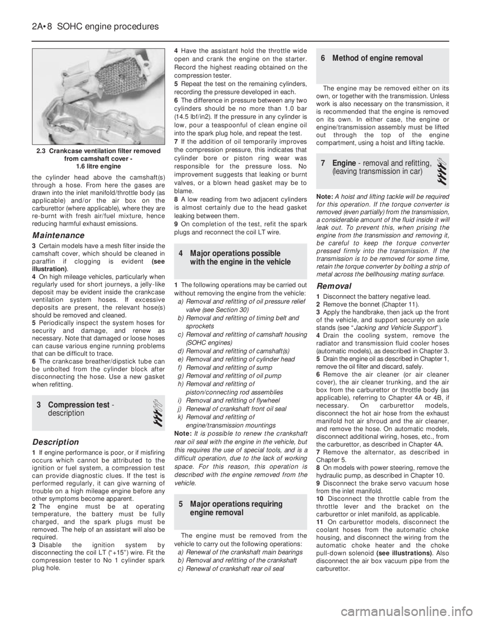
3Certain models have a mesh filter inside the
camshaft cover, which should be cleaned in
paraffin if clogging is evident (see
illustration).
4On high mileage vehicles, particularly when
regularly used for short journeys, a jelly-like
deposit may be evident inside the crankcase
ventilation system hoses. If excessive
deposits are present, the relevant hose(s)
should be removed and cleaned.
5Periodically inspect the system hoses for
security and damage, and renew as
necessary. Note that damaged or loose hoses
can cause various engine running problems
that can be difficult to trace.
6The crankcase breather/dipstick tube can
be unbolted from the cylinder block after
disconnecting the hose. Use a new gasket
when refitting.
3Compression test -
description
3
Description
1If engine performance is poor, or if misfiring
occurs which cannot be attributed to the
ignition or fuel system, a compression test
can provide diagnostic clues. If the test is
performed regularly, it can give warning of
trouble on a high mileage engine before any
other symptoms become apparent.
2The engine must be at operating
temperature, the battery must be fully
charged, and the spark plugs must be
removed. The help of an assistant will also be
required.
3Disable the ignition system by
disconnecting the coil LT (“+15”) wire. Fit the
compression tester to No 1 cylinder spark
plug hole.4Have the assistant hold the throttle wide
open and crank the engine on the starter.
Record the highest reading obtained on the
compression tester.
5Repeat the test on the remaining cylinders,
recording the pressure developed in each.
6The difference in pressure between any two
cylinders should be no more than 1.0 bar
(14.5 lbf/in2). If the pressure in any cylinder is
low, pour a teaspoonful of clean engine oil
into the spark plug hole, and repeat the test.
7If the addition of oil temporarily improves
the compression pressure, this indicates that
cylinder bore or piston ring wear was
responsible for the pressure loss. No
improvement suggests that leaking or burnt
valves, or a blown head gasket may be to
blame.
8A low reading from two adjacent cylinders
is almost certainly due to the head gasket
leaking between them.
9On completion of the test, refit the spark
plugs and reconnect the coil LT wire.
4Major operations possible
with the engine in the vehicle
1The following operations may be carried out
without removing the engine from the vehicle:
a)Removal and refitting of oil pressure relief
valve (see Section 30)
b)Removal and refitting of timing belt and
sprockets
c)Removal and refitting of camshaft housing
(SOHC engines)
d)Removal and refitting of camshaft(s)
e)Removal and refitting of cylinder head
f)Removal and refitting of sump
g)Removal and refitting of oil pump
h)Removal and refitting of
piston/connecting rod assemblies
i)Removal and refitting of flywheel
j)Renewal of crankshaft front oil seal
k)Removal and refitting of
engine/transmission mountings
Note: It is possible to renew the crankshaft
rear oil seal with the engine in the vehicle, but
this requires the use of special tools, and is a
difficult operation, due to the lack of working
space. For this reason, this operation is
described with the engine removed from the
vehicle.
5Major operations requiring
engine removal
The engine must be removed from the
vehicle to carry out the following operations:
a)Renewal of the crankshaft main bearings
b)Removal and refitting of the crankshaft
c)Renewal of crankshaft rear oil seal
6Method of engine removal
The engine may be removed either on its
own, or together with the transmission. Unless
work is also necessary on the transmission, it
is recommended that the engine is removed
on its own. In either case, the engine or
engine/transmission assembly must be lifted
out through the top of the engine
compartment, using a hoist and lifting tackle.
7Engine - removal and refitting,
(leaving transmission in car)
4
Note: A hoist and lifting tackle will be required
for this operation.If the torque converter is
removed (even partially) from the transmission,
a considerable amount of the fluid inside it will
leak out. To prevent this, when prising the
engine from the transmission and removing it,
be careful to keep the torque converter
pressed firmly into the transmission. If the
transmission is to be removed for some time,
retain the torque converter by bolting a strip of
metal across the bellhousing mating surface.
Removal
1Disconnect the battery negative lead.
2Remove the bonnet (Chapter 11).
3Apply the handbrake, then jack up the front
of the vehicle, and support securely on axle
stands (see “Jacking and Vehicle Support”).
4Drain the cooling system, remove the
radiator and transmission fluid cooler hoses
(automatic models), as described in Chapter 3.
5Drain the engine oil as described in Chapter 1,
remove the oil filter and discard, safely.
6Remove the air cleaner (or air cleaner
cover), the air cleaner trunking, and the air
box from the carburettor or throttle body (as
applicable), referring to Chapter 4A or 4B, if
necessary. On carburettor models,
disconnect the hot air hose from the exhaust
manifold hot air shroud and the air cleaner,
and remove the hose. On automatic models,
disconnect additional wiring, hoses, etc., from
the carburettor, as described in Chapter 4A.
7Remove the alternator, as described in
Chapter 5.
8On models with power steering, remove the
hydraulic pump, as described in Chapter 10.
9Disconnect the brake servo vacuum hose
from the inlet manifold.
10Disconnect the throttle cable from the
throttle lever and the bracket on the
carburettor or inlet manifold, as applicable.
11On carburettor models, disconnect the
coolant hoses from the automatic choke
housing, and disconnect the wiring from the
automatic choke heater and the choke
pull-down solenoid (see illustrations). Also
disconnect the air box vacuum pipe from the
carburettor.
2A•8SOHC engine procedures
2.3 Crankcase ventilation filter removed
from camshaft cover -
1.6 litre engine
Page 209 of 525
9Engine and transmission
mountings - renewal
3
Note: New left and right-hand
engine/transmission mounting-to-body bolts
must be used on refitting
1The engine/transmission assembly is
suspended in the engine compartment on
three mountings, two of which are attached to
the transmission, and one to the engine.
Right-hand mounting
2If not already done, apply the handbrake,
then raise the front of the vehicle, and support
securely on axle stands (see “Jacking and
Vehicle Support”)..
3Attach lifting tackle and a hoist to the
engine lifting brackets on the cylinder head,
and support the weight of the engine.
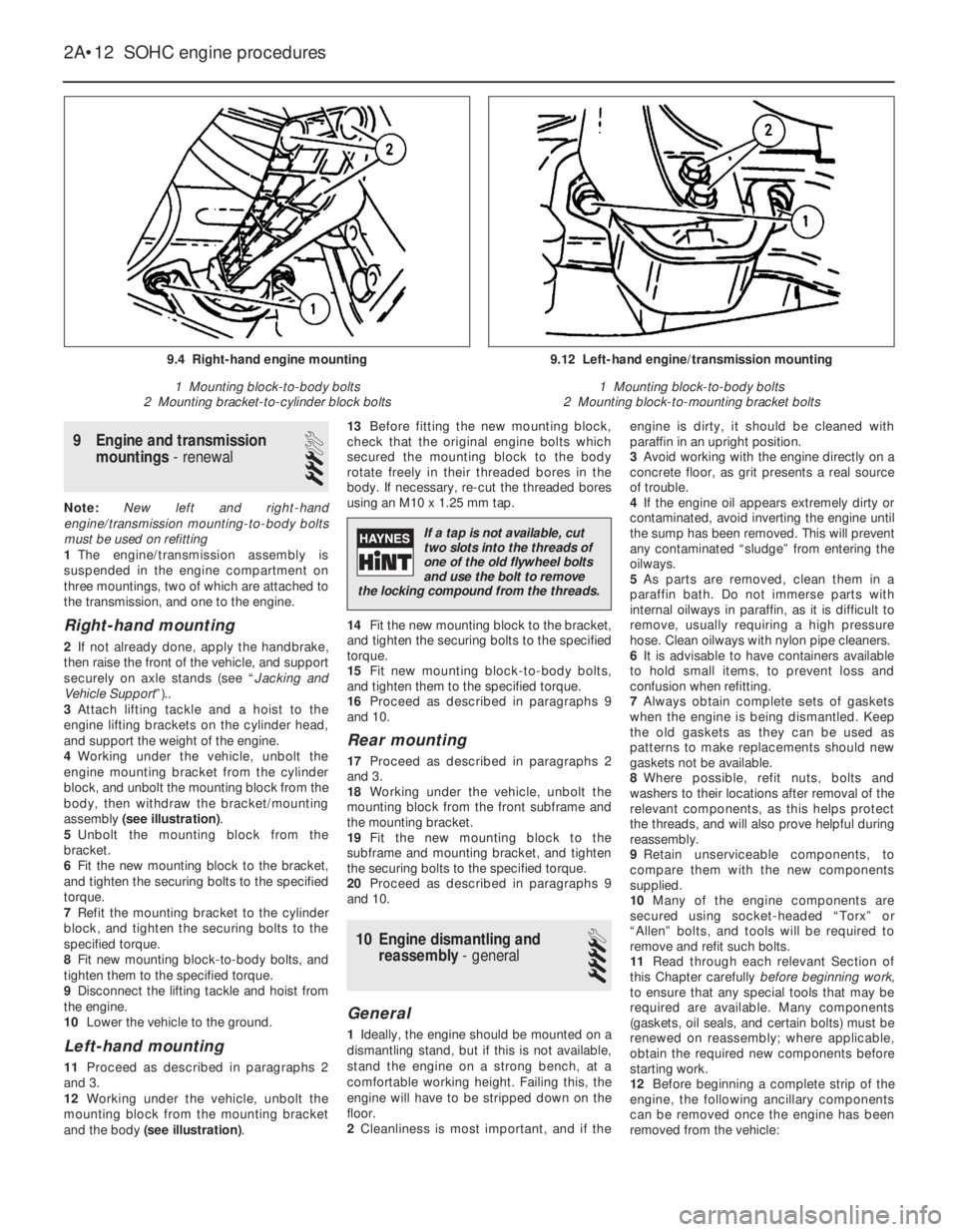
4Working under the vehicle, unbolt the
engine mounting bracket from the cylinder
block, and unbolt the mounting block from the
body, then withdraw the bracket/mounting
assembly (see illustration).
5Unbolt the mounting block from the
bracket.
6Fit the new mounting block to the bracket,
and tighten the securing bolts to the specified
torque.
7Refit the mounting bracket to the cylinder
block, and tighten the securing bolts to the
specified torque.
8Fit new mounting block-to-body bolts, and
tighten them to the specified torque.
9Disconnect the lifting tackle and hoist from
the engine.
10Lower the vehicle to the ground.
Left-hand mounting
11Proceed as described in paragraphs 2
and 3.
12Working under the vehicle, unbolt the
mounting block from the mounting bracket
and the body (see illustration).13Before fitting the new mounting block,
check that the original engine bolts which
secured the mounting block to the body
rotate freely in their threaded bores in the
body. If necessary, re-cut the threaded bores
using an M10 x 1.25 mm tap.
14Fit the new mounting block to the bracket,
and tighten the securing bolts to the specified
torque.
15Fit new mounting block-to-body bolts,
and tighten them to the specified torque.
16Proceed as described in paragraphs 9
and 10.
Rear mounting
17Proceed as described in paragraphs 2
and 3.
18Working under the vehicle, unbolt the
mounting block from the front subframe and
the mounting bracket.
19Fit the new mounting block to the
subframe and mounting bracket, and tighten
the securing bolts to the specified torque.
20Proceed as described in paragraphs 9
and 10.
10Engine dismantling and
reassembly - general
4
General
1Ideally, the engine should be mounted on a
dismantling stand, but if this is not available,
stand the engine on a strong bench, at a
comfortable working height. Failing this, the
engine will have to be stripped down on the
floor.
2Cleanliness is most important, and if theengine is dirty, it should be cleaned with
paraffin in an upright position.
3Avoid working with the engine directly on a
concrete floor, as grit presents a real source
of trouble.
4If the engine oil appears extremely dirty or
contaminated, avoid inverting the engine until
the sump has been removed. This will prevent
any contaminated “sludge” from entering the
oilways.
5As parts are removed, clean them in a
paraffin bath. Do not immerse parts with
internal oilways in paraffin, as it is difficult to
remove, usually requiring a high pressure
hose. Clean oilways with nylon pipe cleaners.
6It is advisable to have containers available
to hold small items, to prevent loss and
confusion when refitting.
7Always obtain complete sets of gaskets
when the engine is being dismantled. Keep
the old gaskets as they can be used as
patterns to make replacements should new
gaskets not be available.
8Where possible, refit nuts, bolts and
washers to their locations after removal of the
relevant components, as this helps protect
the threads, and will also prove helpful during
reassembly.
9Retain unserviceable components, to
compare them with the new components
supplied.
10Many of the engine components are
secured using socket-headed “Torx” or
“Allen” bolts, and tools will be required to
remove and refit such bolts.
11Read through each relevant Section of
this Chapter carefullybeforebeginning work,
to ensure that any special tools that may be
required are available. Many components
(gaskets, oil seals, and certain bolts) must be
renewed on reassembly; where applicable,
obtain the required new components before
starting work.
12Before beginning a complete strip of the
engine, the following ancillary components
can be removed once the engine has been
removed from the vehicle:
2A•12SOHC engine procedures
9.4 Right-hand engine mounting
1 Mounting block-to-body bolts
2 Mounting bracket-to-cylinder block bolts9.12 Left-hand engine/transmission mounting
1 Mounting block-to-body bolts
2 Mounting block-to-mounting bracket bolts
If a tap is not available, cut
two slots into the threads of
one of the old flywheel bolts
and use the bolt to remove
the locking compound from the threads.
Page 224 of 525
28Crankshaft rear oil seal -
renewal
4
Renewal
1With the engine removed from the vehicle,
remove the flywheel, or flexplate (as
applicable) as described in Sections 25 and
26.
2Punch or drill a small hole in the centre of
the now-exposed oil seal. Screw in a
self-tapping screw, and pull on the screw with
pliers to extract the seal. Several attempts
may be necessary. Be careful not to damage
the sealing face of the crankshaft.
3Clean the oil seal seat with a wooden or
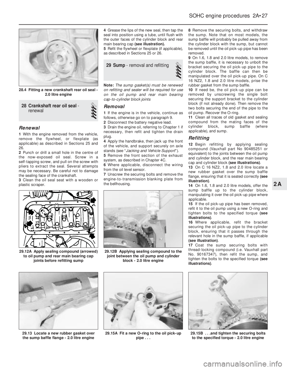
plastic scraper.4Grease the lips of the new seal, then tap the
seal into position using a tube, until flush with
the outer faces of the cylinder block and rear
main bearing cap (see illustration).
5Refit the flywheel or flexplate (if applicable),
as described in Sections 25 or 26.
29Sump - removal and refitting
4
Note: The sump gasket(s) must be renewed
on refitting and sealer will be required for use
on the oil pump and rear main bearing
cap-to-cylinder block joints
Removal
1If the engine is in the vehicle, continue as
follows, otherwise go on to paragraph 9.
2Disconnect the battery negative lead.
3Drain the engine oil, referring to Chapter 1 if
necessary, then refit and tighten the drain
plug.
4Apply the handbrake, then jack up the front
of the vehicle, and support securely on axle
stands (see “Jacking and Vehicle Support”).
5Remove the front section of the exhaust
system, as described in Chapter 4C.
6Where applicable, disconnect the wiring
from the oil level sensor.
7Unscrew the securing bolts and remove the
engine-to-transmission blanking plate from
the bellhousing.8Remove the securing bolts, and withdraw
the sump. Note that on most models, the
sump baffle will probably be pulled away from
the cylinder block with the sump, but cannot
be removed until the oil pick-up pipe has been
removed.
9On 1.6, 1.8 and 2.0 litre models, to remove
the sump baffle, it is necessary to unbolt the
bracket securing the oil pick-up pipe to the
cylinder block. The baffle can then be
manipulated over the oil pick-up pipe. On C
16 NZ2, 1.8 and 2.0 litre models, prise the
rubber gasket from the sump baffle.
10If need be, the oil pick-up pipe can be
removed by unscrewing the single bolt
securing the support bracket to the cylinder
block (if not already done). Then remove the
two bolts securing the end of the pipe to the
oil pump. Recover the O-ring.
11Clean all traces of old gasket and sealing
compound from the mating faces of the
cylinder block, sump baffle (where
applicable), and sump.
Refitting
12Begin refitting by applying sealing
compound (Vauxhall part No 90485251 or
equivalent) to the joints between the oil pump
and cylinder block, and the rear main bearing
cap and cylinder block (see illustrations).
13On C 16 NZ2, 1.8 and 2.0 litre locate a
new rubber gasket over the sump baffle
flange, ensuring that it is seated correctly (see
illustration).
14On 1.6, 1.8 and 2.0 litre models, offer the
sump baffle up to the cylinder block,
manipulating it over the oil pick-up pipe where
applicable.
15If the oil pick-up pipe has been removed,
refit it to the oil pump using a new O-ring and
tighten bolts to the specified torque (see
illustrations).
16Where applicable, refit the bracket
securing the oil pick-up pipe to the cylinder
block, ensuring that it passes through the
relevant hole in the sump baffle, if applicable
(see illustration).
17Coat the sump securing bolts with
thread-locking compound (i.e. Vauxhall part
No. 90167347), then refit the sump, and
tighten the bolts to the specified torque (see
illustrations).
SOHC engine procedures 2A•27
29.12B Applying sealing compound to the
joint between the oil pump and cylinder
block - 2.0 litre engine
29.15B . . .and tighten the securing bolts
to the specified torque - 2.0 litre engine29.15A Fit a new O-ring to the oil pick-up
pipe . . .29.13 Locate a new rubber gasket over
the sump baffle flange - 2.0 litre engine
29.12A Apply sealing compound (arrowed)
to oil pump and rear main bearing cap
joints before refitting sump
28.4 Fitting a new crankshaft rear oil seal -
2.0 litre engine
2A
Page 240 of 525
REF
Overall length: *
Saloon models . . . . . . . . . . . . . . . . . . . . . . . . . . . . . . . . . . .4432 mm
Hatchback models . . . . . . . . . . . . . . . . . . . . . . . . . . . . . . . .4352 mm
Overall width: *
All models . . . . . . . . . . . . . . . . . . . . . . . . . . . . . . . . . . . . . .1876 mm
Overall height (unladen): *
All models . . . . . . . . . . . . . . . . . . . . . . . . . . . . . . . . . . . . . .1400 mm
Wheelbase: *
All models . . . . . . . . . . . . . . . . . . . . . . . . . . . . . . . . . . . . . .2600 mm
Track:
Front: *
All models . . . . . . . . . . . . . . . . . . . . . . . . . . . . . . . . . . . .1426 mm
Rear: *
All models . . . . . . . . . . . . . . . . . . . . . . . . . . . . . . . . . . . .1423 mm
Ground clearance (minimum): *
All models . . . . . . . . . . . . . . . . . . . . . . . . . . . . . . . . . . . . . . . . .120 mm
Weights
Kerb weight: *
Dependent on model . . . . . . . . . . . . . . . . . . . . . . . . . .1098 ± 101 kg
Maximum gross vehicle weight: *
All models . . . . . . . . . . . . . . . . . . . . . . . . . . . . . . . .Refer to VIN plate
Maximum roof rack load: *
All models . . . . . . . . . . . . . . . . . . . . . . . . . . . . . . . . . . . . . . . .100 kg
Maximum towing hitch downward load: *
All models . . . . . . . . . . . . . . . . . . . . . . . . . . . . . . . . . . . . . . . . .75 kg
Maximum towing weight: *
Trailer with brakes . . . . . . . . . . . . . . . . . . . . . . . . . . . .1175 ± 175 kg
Trailer without brakes . . . . . . . . . . . . . . . . . . . . . . . . . . .550 ± 50 kg
* Exact details depend upon model and specification.
Refer to owners handbook.
Dimensions and Weights . . . . . . . . . . . . . . . . . .REF•1
Conversion Factors . . . . . . . . . . . . . . . . . . . . . . .REF•2
Buying Spare Parts . . . . . . . . . . . . . . . . . . . . . . .REF•3
Vehicle Identification . . . . . . . . . . . . . . . . . . . . . .REF•3
General Repair Procedures . . . . . . . . . . . . . . . . .REF•4
Jacking and Vehicle Support . . . . . . . . . . . . . . .REF•5Radio/cassette unit Anti-theft System . . . . . . . .REF•5
Tools and Working Facilities . . . . . . . . . . . . . . . .REF•6
MOT Test Checks . . . . . . . . . . . . . . . . . . . . . . . .REF•8
Fault Finding . . . . . . . . . . . . . . . . . . . . . . . . . . .REF•12
Glossary of Technical Terms . . . . . . . . . . . . . . .REF•20
Index . . . . . . . . . . . . . . . . . . . . . . . . . . . . . . . . .REF•25
Reference REF•1
Dimensions and Weights
Page 244 of 525
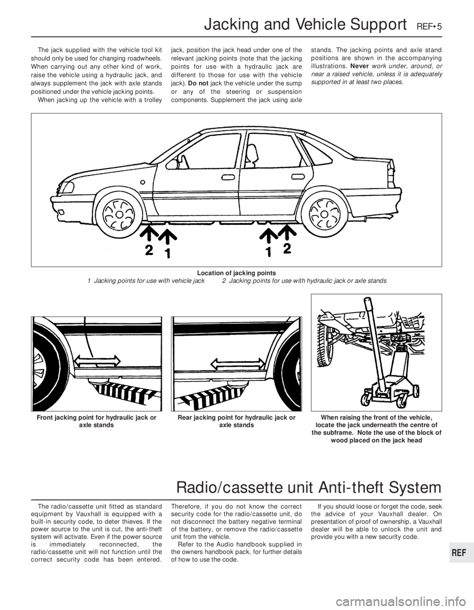
The jack supplied with the vehicle tool kit
should only be used for changing roadwheels.
When carrying out any other kind of work,
raise the vehicle using a hydraulic jack, and
always supplement the jack with axle stands
positioned under the vehicle jacking points.
When jacking up the vehicle with a trolleyjack, position the jack head under one of the
relevant jacking points (note that the jacking
points for use with a hydraulic jack are
different to those for use with the vehicle
jack). Do not jack the vehicle under the sump
or any of the steering or suspension
components. Supplement the jack using axlestands. The jacking points and axle stand
positions are shown in the accompanying
illustrations. Never work under, around, or
near a raised vehicle, unless it is adequately
supported in at least two places.
The radio/cassette unit fitted as standard
equipment by Vauxhall is equipped with a
built-in security code, to deter thieves. If the
power source to the unit is cut, the anti-theft
system will activate. Even if the power source
is immediately reconnected, the
radio/cassette unit will not function until the
correct security code has been entered.Therefore, if you do not know the correct
security code for the radio/cassette unit, do
not disconnect the battery negative terminal
of the battery, or remove the radio/cassette
unit from the vehicle.
Refer to the Audio handbook supplied in
the owners handbook pack, for further details
of how to use the code.If you should loose or forget the code, seek
the advice of your Vauxhall dealer. On
presentation of proof of ownership, a Vauxhall
dealer will be able to unlock the unit and
provide you with a new security code.
Jacking and Vehicle Support REF•5
Rear jacking point for hydraulic jack or
axle standsWhen raising the front of the vehicle,
locate the jack underneath the centre of
the subframe. Note the use of the block of
wood placed on the jack headFront jacking point for hydraulic jack or
axle stands
Location of jacking points
1 Jacking points for use with vehicle jack 2 Jacking points for use with hydraulic jack or axle stands
REF
Radio/cassette unit Anti-theft System
Page 265 of 525
oil and filter renewal - 0•17, 1•2, 1•9
oil cooler - 2B•10
oil level - 0•12
oil pump - 2A•28, 2B•9
piston rings - 2A•30
piston/connecting rod - 2A•29
removal - 2A•8, 2B•3
SOHC - 2A•1 et seq
sump - 2A•27, 2B•9
timing belt - 2A•13, 2B•3, 2B•6
undershield - 11•13
valve lifters - 2A•24, 2B•9
valves - 2A•5, 2B•2
Environmental considerations- REF•4
Exhaust manifold- 4C•5
Exhaust system check- 1•11, 4C•5
Expansion tank- 3•5
FFan (radiator)- 3•5
Fault diagnosis- REF•12 et seq
automatic transmission - REF•12, REF•16
braking system - REF•12, REF•17
clutch - REF•12, REF•15
cooling system - REF•12, REF•15
driveshafts - REF•12, REF•16
electrical system - REF•12, REF•18
engine - REF•12, REF•13
fuel and exhaust systems - REF•12, REF•15
manual transmission - REF•12, REF•16
steering - REF•12, REF•17
suspension - REF•12, REF•17
Flexplate (automatic transmission)- 2A•26
Flushing (cooling system)- 3•2
Flywheel- 2A•26
Foglamp- 12•11
Fuel and exhaust (carburettor) systems-
4A•1 et seq
Fuel and exhaust (fuel injection) systems-
4B•1 et seq
Fuel and exhaust systems - emissions-
4C•1 et seq
Fuel and exhaust systems:
accelerator cable - 4A•5
accelerator pedal - 4A•5
air box - 4B•5
air cleaner - 1•3, 1•13, 4A•3, 4B•4
air pump/cut off valve - 4C•2
air temperature control - 4B•5
airflow meters - 4B•12
automatic choke - 4A•9
carbon canister - 4C•4
carburettor - 4A•5, 4A•11
catalytic converter - 4C•3
control unit - 4B•16
depressurising fuel system - 4B•5
EGR components - 4C•2
exhaust manifold - 4C•5
exhaust system check - 1•11, 4C•5
fault diagnosis - REF•12, REF•15
filler cap - 11•13
fuel filters - 1•3, 1•14, 4B•6
fuel flow damper - 4B•8
fuel injector(s) - 4B•13
fuel level sender unit - 4A•4, 4B•8
fuel pressure regulator - 4B•10
fuel pump - 4A•3, 4B•6fuel tank - 4A•4, 4B•7
fuel vapour separator - 4A•4
idle speed/mixture adjustment - 4A•7,
4A•12, 4B•9, 4B•11
inlet manifold - 4A•12, 4B•17
knock sensor - 4B•17
lambda sensor - 4C•4
manifolds - 4A•12, 4B•17, 4C•5
mixture (CO) - 4A•7, 4A•12, 4B•9
oxygen sensor - 4C•4
Pierburg 2E3 - 4A•5
potentiometer - 4B•12, 4B•16
throttle cable - 4A•5
throttle pedal - 4A•5
Fuses- 12•1, 12•3
GGear selector linkage- 7A•2
Gearbox - see Manual or Automatic
transmission
Gearbox oil- 0•17, 1•2, 1•15
Gearchange lever- 7A•3
Glass- 11•9
Glossary of technical terms- REF•20
Glove compartment- 11•18
HHandbrake adjustment- 9•18
Handbrake cables- 9•19
Handbrake lever- 9•20
Handles (door)- 11•7
Hazard warning switch- 12•4
Headlamp alignment- 12•10
Headlamp unit- 12•9
Headlining- 11•19
Heater blower motor switch- 12•4
Heater control panel- 3•6
Heater matrix- 3•7
Heating systems- 3•1 et seq
Horn- 12•8
Hose and fluid leak check- 0•9, 1•9
Hoses brake- 9•18
IIdle speed/mixture/adjustment- 4A•7,
4A•12, 4B•9, 4B•11
Ignition coil- 5•9
Ignition switch- 12•3
Ignition system- 5•2
Igniton timing- 5•2, 5•13
Indicator lamps- 12•11
Indicator switch- 12•4
Injector(s)- 4B•13
Inlet manifold- 4A•12, 4B•17
Input shaft (clutch) oil seal- 7A•4
Instrument panel- 12•6
Interior lamps- 12•8
Interior trim panels- 11•14
Introduction to the Vauxhall Cavalier- 0•4
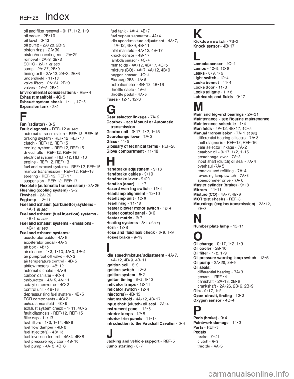
JJacking and vehicle support- REF•5
Jump starting- 0•7
KKickdown switch - 7B•3
Knock sensor- 4B•17
LLambda sensor- 4C•4
Lamps- 12•8, 12•9
Leaks- 0•9, 1•9
Light switch- 12•4
Locks bonnet- 11•4
Locks door- 11•8
Locks tailgate- 11•6
Lubricants and fluids- 0•17
MMain and big-end bearings- 2A•31
Maintenance - see Routine maintenance
Maintenance schedule- 1•4
Manifolds- 4A•12, 4B•17, 4C•5
Manual transmission- 7A•1 et seq
differential bearing oil seals - 7A•3
fault diagnosis - REF•12, REF•16
gear selector linkage - 7A•2
gearbox oil - 0•17, 1•2, 1•15
gearchange lever - 7A•3
input shaft (clutch) oil seal - 7A•4
overhaul -7A•5
removal and refitting - 7A•4
reversing lamp switch - 7A•6
speedometer drive - 7A•6
Master cylinder (brake)- 9•13
Mirrors- 11•11
Mixture (CO)- 4A•7, 4B•9
MOT test checks- REF•8
Mountings (engine/transmission)- 2A•12,
2B•3
NNumber plate lamp- 12•11
OOil change- 0•17, 1•2, 1•9
Oil cooler- 2B•10
Oil filter- 1•2, 1•9
Oil pressure warning lamp switch- 12•5
Oil pump- 2A•28, 2B•9
Oil seals:
differential bearing - 7A•3
general - REF •4
camshaft - 2A•18, 2B•6
crankshaft - 2A•26, 2B•6, 2B•9
Oils- 0•17, 1•2
Open-circuit, finding - 12•2
Oxygen sensor- 4C•4
PPads (brake)- 9•4
Paintwork damage- 11•2
Parts- REF•3
Pedals
brake - 9•21
clutch - 6•3
throttle - 4A•5
REF•26Index