1988 OPEL VECTRA transmission
[x] Cancel search: transmissionPage 1 of 525
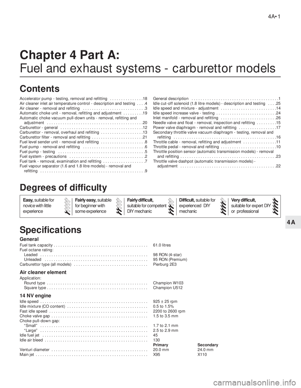
4A
General
Fuel tank capacity . . . . . . . . . . . . . . . . . . . . . . . . . . . . . . . . . . . . . . . . . . 61.0 litres
Fuel octane rating:
Leaded . . . . . . . . . . . . . . . . . . . . . . . . . . . . . . . . . . . . . . . . . . . . . . . . 98 RON (4-star)
Unleaded . . . . . . . . . . . . . . . . . . . . . . . . . . . . . . . . . . . . . . . . . . . . . . 95 RON (Premium)
Carburettor type (all models) . . . . . . . . . . . . . . . . . . . . . . . . . . . . . . . . . Pierburg 2E3
Air cleaner element
Application:
Round type . . . . . . . . . . . . . . . . . . . . . . . . . . . . . . . . . . . . . . . . . . . . . Champion W103
Square type . . . . . . . . . . . . . . . . . . . . . . . . . . . . . . . . . . . . . . . . . . . . . Champion U512
14 NV engine
Idle speed . . . . . . . . . . . . . . . . . . . . . . . . . . . . . . . . . . . . . . . . . . . . . . . . 925 ± 25 rpm
Idle mixture (CO content) . . . . . . . . . . . . . . . . . . . . . . . . . . . . . . . . . . . . 0.5 to 1.5%
Fast idle speed . . . . . . . . . . . . . . . . . . . . . . . . . . . . . . . . . . . . . . . . . . . . 2200 to 2600 rpm
Choke valve gap . . . . . . . . . . . . . . . . . . . . . . . . . . . . . . . . . . . . . . . . . . . 1.5 to 3.5 mm
Choke pull-down gap:
“Small” . . . . . . . . . . . . . . . . . . . . . . . . . . . . . . . . . . . . . . . . . . . . . . . . 1.7 to 2.1 mm
“Large” . . . . . . . . . . . . . . . . . . . . . . . . . . . . . . . . . . . . . . . . . . . . . . . . 2.5 to 2.9 mm
Idle fuel jet . . . . . . . . . . . . . . . . . . . . . . . . . . . . . . . . . . . . . . . . . . . . . . . 45
Idle air bleed . . . . . . . . . . . . . . . . . . . . . . . . . . . . . . . . . . . . . . . . . . . . . . 130
Primary Secondary
Venturi diameter . . . . . . . . . . . . . . . . . . . . . . . . . . . . . . . . . . . . . . . . . . . 20.0 mm 24.0 mm
Main jet . . . . . . . . . . . . . . . . . . . . . . . . . . . . . . . . . . . . . . . . . . . . . . . . . . X95 X110
Chapter 4 Part A:
Fuel and exhaust systems - carburettor models
Accelerator pump - testing, removal and refitting . . . . . . . . . . . . . . .18
Air cleaner inlet air temperature control - description and testing . . . .4
Air cleaner - removal and refitting . . . . . . . . . . . . . . . . . . . . . . . . . . . .3
Automatic choke unit - removal, refitting and adjustment . . . . . . . . .19
Automatic choke vacuum pull-down units - removal, refitting and
adjustment . . . . . . . . . . . . . . . . . . . . . . . . . . . . . . . . . . . . . . . . . . .20
Carburettor - general . . . . . . . . . . . . . . . . . . . . . . . . . . . . . . . . . . . . .12
Carburettor - removal, overhaul and refitting . . . . . . . . . . . . . . . . . . .13
Carburettor filter - removal and refitting . . . . . . . . . . . . . . . . . . . . . . .21
Fuel level sender unit - removal and refitting . . . . . . . . . . . . . . . . . . . .8
Fuel pump - removal and refitting . . . . . . . . . . . . . . . . . . . . . . . . . . . .6
Fuel pump - testing . . . . . . . . . . . . . . . . . . . . . . . . . . . . . . . . . . . . . . .5
Fuel system - precautions . . . . . . . . . . . . . . . . . . . . . . . . . . . . . . . . . .2
Fuel tank - removal, examination and refitting . . . . . . . . . . . . . . . . . . .7
Fuel vapour separator (1.6 and 1.8 litre models) - removal and
refitting . . . . . . . . . . . . . . . . . . . . . . . . . . . . . . . . . . . . . . . . . . . . . . .9General description . . . . . . . . . . . . . . . . . . . . . . . . . . . . . . . . . . . . . . .1
Idle cut-off solenoid (1.8 litre models) - description and testing . . . .25
Idle speed and mixture - adjustment . . . . . . . . . . . . . . . . . . . . . . . . .14
Idle speed increase valve - testing . . . . . . . . . . . . . . . . . . . . . . . . . . .24
Inlet manifold - removal and refitting . . . . . . . . . . . . . . . . . . . . . . . . .26
Needle valve and float - removal, inspection and refitting . . . . . . . . .15
Power valve diaphragm - removal and refitting . . . . . . . . . . . . . . . . .17
Secondary throttle valve vacuum diaphragm - testing, removal and
refitting . . . . . . . . . . . . . . . . . . . . . . . . . . . . . . . . . . . . . . . . . . . . . .16
Throttle cable - removal, refitting and adjustment . . . . . . . . . . . . . . .11
Throttle pedal - removal and refitting . . . . . . . . . . . . . . . . . . . . . . . . .10
Throttle position sensor (automatic transmission models) - removal
and refitting . . . . . . . . . . . . . . . . . . . . . . . . . . . . . . . . . . . . . . . . . . .23
Throttle valve dashpot (automatic transmission models) -
adjustment . . . . . . . . . . . . . . . . . . . . . . . . . . . . . . . . . . . . . . . . . . .22
4A•1
Specifications Contents
Easy,suitable for
novice with little
experienceFairly easy,suitable
for beginner with
some experienceFairly difficult,
suitable for competent
DIY mechanic
Difficult,suitable for
experienced DIY
mechanicVery difficult,
suitable for expert DIY
or professional
Degrees of difficulty
54321
Page 2 of 525
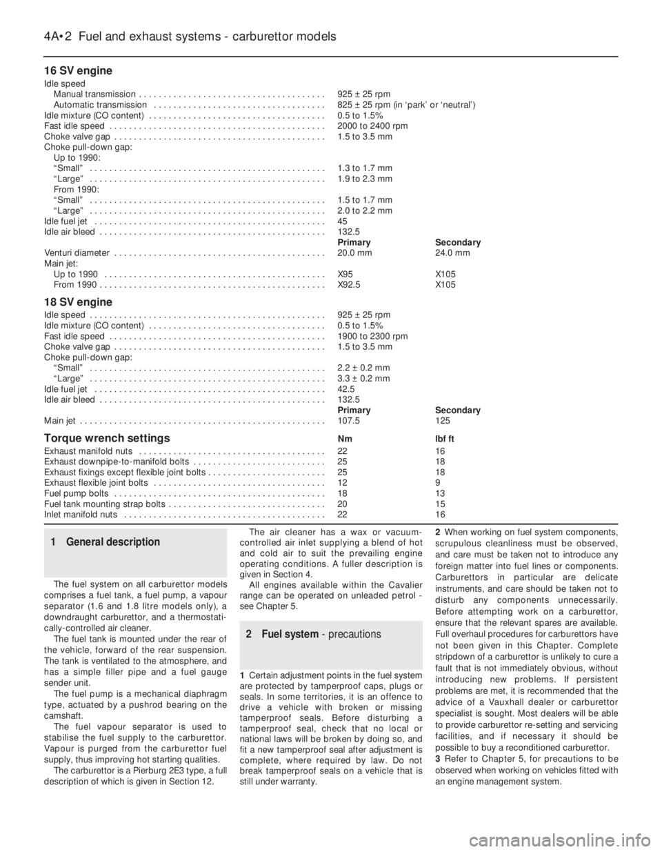
16 SV engine
Idle speed
Manual transmission . . . . . . . . . . . . . . . . . . . . . . . . . . . . . . . . . . . . . .925 ±25 rpm
Automatic transmission . . . . . . . . . . . . . . . . . . . . . . . . . . . . . . . . . . .825 ±25 rpm (in ‘park’ or ‘neutral’)
Idle mixture (CO content) . . . . . . . . . . . . . . . . . . . . . . . . . . . . . . . . . . . .0.5 to 1.5%
Fast idle speed . . . . . . . . . . . . . . . . . . . . . . . . . . . . . . . . . . . . . . . . . . . .2000 to 2400 rpm
Choke valve gap . . . . . . . . . . . . . . . . . . . . . . . . . . . . . . . . . . . . . . . . . . .1.5 to 3.5 mm
Choke pull-down gap:
Up to 1990:
“Small” . . . . . . . . . . . . . . . . . . . . . . . . . . . . . . . . . . . . . . . . . . . . . . . .1.3 to 1.7 mm
“Large” . . . . . . . . . . . . . . . . . . . . . . . . . . . . . . . . . . . . . . . . . . . . . . . .1.9 to 2.3 mm
From 1990:
“Small” . . . . . . . . . . . . . . . . . . . . . . . . . . . . . . . . . . . . . . . . . . . . . . . .1.5 to 1.7 mm
“Large” . . . . . . . . . . . . . . . . . . . . . . . . . . . . . . . . . . . . . . . . . . . . . . . .2.0 to 2.2 mm
Idle fuel jet . . . . . . . . . . . . . . . . . . . . . . . . . . . . . . . . . . . . . . . . . . . . . . .45
Idle air bleed . . . . . . . . . . . . . . . . . . . . . . . . . . . . . . . . . . . . . . . . . . . . . .132.5
PrimarySecondary
Venturi diameter . . . . . . . . . . . . . . . . . . . . . . . . . . . . . . . . . . . . . . . . . . .20.0 mm24.0 mm
Main jet:
Up to 1990 . . . . . . . . . . . . . . . . . . . . . . . . . . . . . . . . . . . . . . . . . . . . .X95X105
From 1990 . . . . . . . . . . . . . . . . . . . . . . . . . . . . . . . . . . . . . . . . . . . . . .X92.5X105
18 SV engine
Idle speed . . . . . . . . . . . . . . . . . . . . . . . . . . . . . . . . . . . . . . . . . . . . . . . .925 ±25 rpm
Idle mixture (CO content) . . . . . . . . . . . . . . . . . . . . . . . . . . . . . . . . . . . .0.5 to 1.5%
Fast idle speed . . . . . . . . . . . . . . . . . . . . . . . . . . . . . . . . . . . . . . . . . . . .1900 to 2300 rpm
Choke valve gap . . . . . . . . . . . . . . . . . . . . . . . . . . . . . . . . . . . . . . . . . . .1.5 to 3.5 mm
Choke pull-down gap:
“Small” . . . . . . . . . . . . . . . . . . . . . . . . . . . . . . . . . . . . . . . . . . . . . . . .2.2 ±0.2 mm
“Large” . . . . . . . . . . . . . . . . . . . . . . . . . . . . . . . . . . . . . . . . . . . . . . . .3.3 ±0.2 mm
Idle fuel jet . . . . . . . . . . . . . . . . . . . . . . . . . . . . . . . . . . . . . . . . . . . . . . .42.5
Idle air bleed . . . . . . . . . . . . . . . . . . . . . . . . . . . . . . . . . . . . . . . . . . . . . .132.5
PrimarySecondary
Main jet . . . . . . . . . . . . . . . . . . . . . . . . . . . . . . . . . . . . . . . . . . . . . . . . . .107.5125
Torque wrench settingsNmlbf ft
Exhaust manifold nuts . . . . . . . . . . . . . . . . . . . . . . . . . . . . . . . . . . . . . .2216
Exhaust downpipe-to-manifold bolts . . . . . . . . . . . . . . . . . . . . . . . . . . .2518
Exhaust fixings except flexible joint bolts . . . . . . . . . . . . . . . . . . . . . . . .2518
Exhaust flexible joint bolts . . . . . . . . . . . . . . . . . . . . . . . . . . . . . . . . . . .129
Fuel pump bolts . . . . . . . . . . . . . . . . . . . . . . . . . . . . . . . . . . . . . . . . . . .1813
Fuel tank mounting strap bolts . . . . . . . . . . . . . . . . . . . . . . . . . . . . . . . .2015
Inlet manifold nuts . . . . . . . . . . . . . . . . . . . . . . . . . . . . . . . . . . . . . . . . .2216
1General description
The fuel system on all carburettor models
comprises a fuel tank, a fuel pump, a vapour
separator (1.6 and 1.8 litre models only), a
downdraught carburettor, and a thermostati-
cally-controlled air cleaner.
The fuel tank is mounted under the rear of
the vehicle, forward of the rear suspension.
The tank is ventilated to the atmosphere, and
has a simple filler pipe and a fuel gauge
sender unit.
The fuel pump is a mechanical diaphragm
type, actuated by a pushrod bearing on the
camshaft.
The fuel vapour separator is used to
stabilise the fuel supply to the carburettor.
Vapour is purged from the carburettor fuel
supply, thus improving hot starting qualities.
The carburettor is a Pierburg 2E3 type, a full
description of which is given in Section 12.The air cleaner has a wax or vacuum-
controlled air inlet supplying a blend of hot
and cold air to suit the prevailing engine
operating conditions. A fuller description is
given in Section 4.
All engines available within the Cavalier
range can be operated on unleaded petrol -
see Chapter 5.
2Fuel system - precautions
1Certain adjustment points in the fuel system
are protected by tamperproof caps, plugs or
seals. In some territories, it is an offence to
drive a vehicle with broken or missing
tamperproof seals. Before disturbing a
tamperproof seal, check that no local or
national laws will be broken by doing so, and
fit a new tamperproof seal after adjustment is
complete, where required by law. Do not
break tamperproof seals on a vehicle that is
still under warranty.2When working on fuel system components,
scrupulous cleanliness must be observed,
and care must be taken not to introduce any
foreign matter into fuel lines or components.
Carburettors in particular are delicate
instruments, and care should be taken not to
disturb any components unnecessarily.
Before attempting work on a carburettor,
ensure that the relevant spares are available.
Full overhaul procedures for carburettors have
not been given in this Chapter. Complete
stripdown of a carburettor is unlikely to cure a
fault that is not immediately obvious, without
introducing new problems. If persistent
problems are met, it is recommended that the
advice of a Vauxhall dealer or carburettor
specialist is sought. Most dealers will be able
to provide carburettor re-setting and servicing
facilities, and if necessary it should be
possible to buy a reconditioned carburettor.
3Refer to Chapter 5, for precautions to be
observed when working on vehicles fitted with
an engine management system.
4A•2Fuel and exhaust systems - carburettor models
Page 12 of 525
Refitting
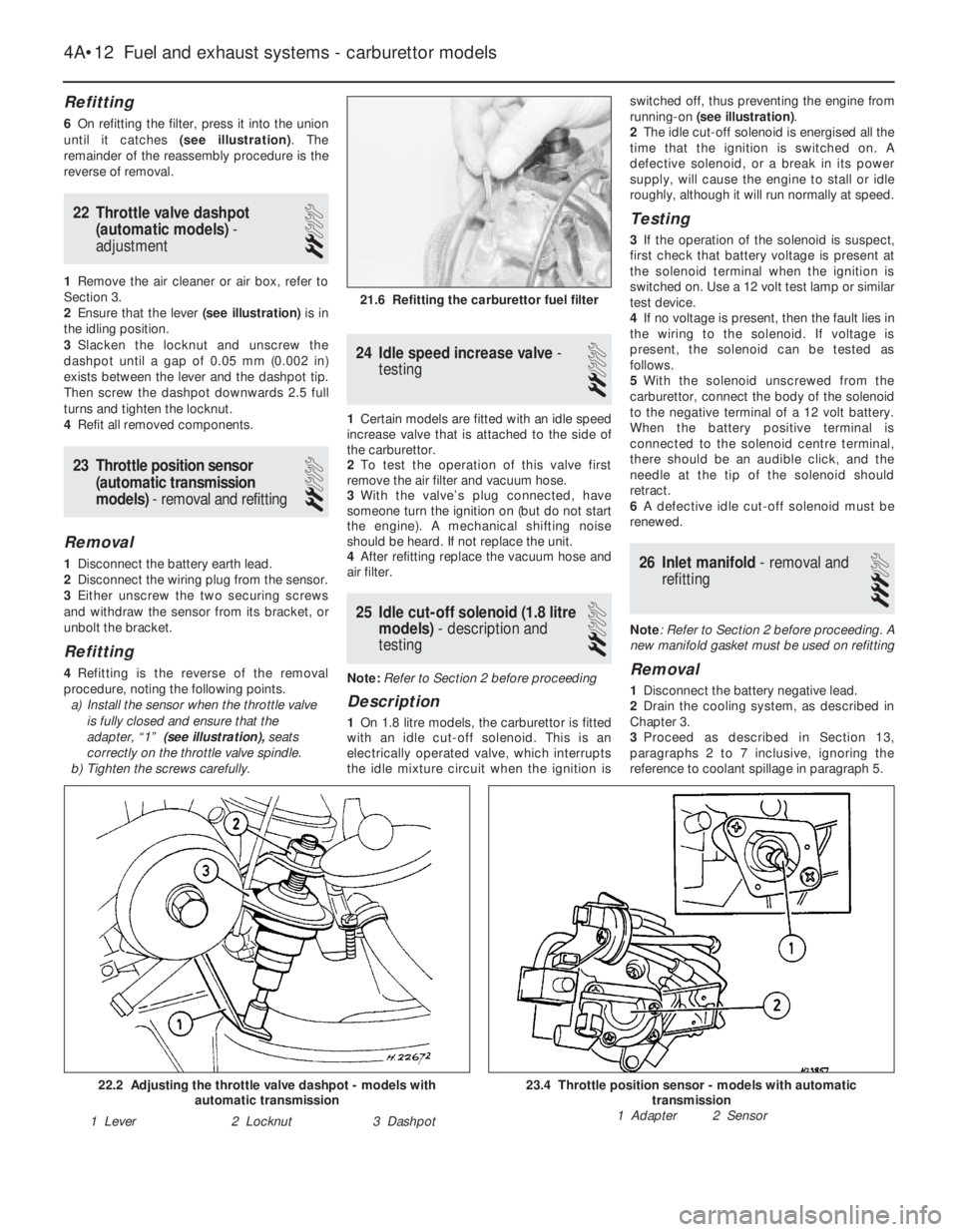
6On refitting the filter, press it into the union
until it catches (see illustration). The
remainder of the reassembly procedure is the
reverse of removal.
22Throttle valve dashpot
(automatic models) -
adjustment
2
1Remove the air cleaner or air box, refer to
Section 3.
2Ensure that the lever (see illustration)is in
the idling position.
3Slacken the locknut and unscrew the
dashpot until a gap of 0.05 mm (0.002 in)
exists between the lever and the dashpot tip.
Then screw the dashpot downwards 2.5 full
turns and tighten the locknut.
4Refit all removed components.
23Throttle position sensor
(automatic transmission
models) - removal and refitting
2
Removal
1Disconnect the battery earth lead.
2Disconnect the wiring plug from the sensor.
3Either unscrew the two securing screws
and withdraw the sensor from its bracket, or
unbolt the bracket.
Refitting
4Refitting is the reverse of the removal
procedure, noting the following points.
a)Install the sensor when the throttle valve
is fully closed and ensure that the
adapter, “1” (see illustration),seats
correctly on the throttle valve spindle.
b)Tighten the screws carefully.
24Idle speed increase valve -
testing
2
1Certain models are fitted with an idle speed
increase valve that is attached to the side of
the carburettor.
2To test the operation of this valve first
remove the air filter and vacuum hose.
3With the valve’s plug connected, have
someone turn the ignition on (but do not start
the engine). A mechanical shifting noise
should be heard. If not replace the unit.
4After refitting replace the vacuum hose and
air filter.
25Idle cut-off solenoid (1.8 litre
models) - description and
testing
2
Note: Refer to Section 2 before proceeding
Description
1On 1.8 litre models, the carburettor is fitted
with an idle cut-off solenoid. This is an
electrically operated valve, which interrupts
the idle mixture circuit when the ignition isswitched off, thus preventing the engine from
running-on (see illustration).
2The idle cut-off solenoid is energised all the
time that the ignition is switched on. A
defective solenoid, or a break in its power
supply, will cause the engine to stall or idle
roughly, although it will run normally at speed.
Testing
3If the operation of the solenoid is suspect,
first check that battery voltage is present at
the solenoid terminal when the ignition is
switched on. Use a 12 volt test lamp or similar
test device.
4If no voltage is present, then the fault lies in
the wiring to the solenoid. If voltage is
present, the solenoid can be tested as
follows.
5With the solenoid unscrewed from the
carburettor, connect the body of the solenoid
to the negative terminal of a 12 volt battery.
When the battery positive terminal is
connected to the solenoid centre terminal,
there should be an audible click, and the
needle at the tip of the solenoid should
retract.
6A defective idle cut-off solenoid must be
renewed.
26Inlet manifold - removal and
refitting
3
Note: Refer to Section 2 before proceeding. A
new manifold gasket must be used on refitting
Removal
1Disconnect the battery negative lead.
2Drain the cooling system, as described in
Chapter 3.
3Proceed as described in Section 13,
paragraphs 2 to 7 inclusive, ignoring the
reference to coolant spillage in paragraph 5.
4A•12Fuel and exhaust systems - carburettor models
21.6 Refitting the carburettor fuel filter
23.4 Throttle position sensor - models with automatic
transmission
1 Adapter 2 Sensor22.2 Adjusting the throttle valve dashpot - models with
automatic transmission
1 Lever2 Locknut3 Dashpot
Page 16 of 525
1General information and
precautions
The electrical system is of 12-volt negative
earth type. Power for the lights and all
electrical accessories is supplied by a
lead/acid type battery, which is charged by
the alternator.
This Chapter covers repair and service
procedures for the various electrical
components not associated with engine.
Information on the battery, alternator and
starter motor can be found in Chapter 5.
It should be noted that, before working on
any component in the electrical system, the
battery negative terminal should first be
disconnected, to prevent the possibility of
electrical short-circuits and/or fires.
Whenever the occasion arises, carefully
check the routing of the wiring harness,
ensuring that it is correctly secured by the
clips or ties provided so that it cannot chafe
against other components. Carefully check
points such as the clutch cable bracket,
clutch housing and harness support bracket,
the inlet manifold, the horn mounting bracket,
the starter motor terminals, and the rear
bumper and number plate lamp.
If evidence is found of the harness having
chafed against other components, repair the
damage and ensure that the harness is
secured or protected so that the problem
cannot occur again.
2Electrical fault-finding -
general information
Note:Refer to the precautions given in “Safety
first!” (at the beginning of this manual) and to
Section 1 of this Chapter before starting work.
The following tests relate to testing of the main
electrical circuits, and should not be used to
test delicate electronic circuits (such as anti-
lock braking systems), particularly where an
electronic control module is used.
A typical electrical circuit consists of an
electrical component, any switches, relays,
motors, fuses, fusible links or circuit breakers
related to that component, and the wiring and
connectors that link the component to boththe battery and the chassis. To help to
pinpoint a problem in an electrical circuit,
wiring diagrams are included at the end of this
Chapter.
Before attempting to diagnose an electrical
fault, first study the appropriate wiring
diagram, to obtain a complete understanding
of the components included in the particular
circuit concerned. The possible sources of a
fault can be narrowed down by noting
whether other components related to the
circuit are operating properly. If several
components or circuits fail at one time, the
problem is likely to be related to a shared fuse
or earth connection.
Electrical problems usually stem from
simple causes, such as loose or corroded
connections, a faulty earth connection, a
blown fuse, a melted fusible link, or a faulty
relay (refer to Section 3 for details of testing
relays). Visually inspect the condition of all
fuses, wires and connections in a problem
circuit before testing the components. Use
the wiring diagrams to determine which
terminal connections will need to be checked,
to pinpoint the trouble-spot.
The basic tools required for electrical fault-
finding include the following:
a)a circuit tester or voltmeter (a 12-volt bulb
with a set of test leads can also be used
for certain tests).
b)a self-powered test light (sometimes
known as a continuity tester).
c)an ohmmeter (to measure resistance).
d)a battery.
e)a set of test leads.
f)a jumper wire, preferably with a circuit
breaker or fuse incorporated, which can
be used to bypass suspect wires or
electrical components.
Before attempting to locate a problem with
test instruments, use the wiring diagram to
determine where to make the connections.
To find the source of an intermittent wiring
fault (usually due to a poor or dirty
connection, or damaged wiring insulation), a
“wiggle” test can be performed on the wiring.
This involves wiggling the wiring by hand, to
see if the fault occurs as the wiring is moved.
It should be possible to narrow down the
source of the fault to a particular section of
wiring. This method of testing can be used in
conjunction with any of the tests described in
the following sub-Sections.
Apart from problems due to poor
connections, two basic types of fault can
occur in an electrical circuit - open-circuit, or
short-circuit.
Open-circuit faults are caused by a break
somewhere in the circuit, which prevents
current from flowing. An open-circuit fault will
prevent a component from working, but will
not cause the relevant circuit fuse to blow.
Short-circuit faults are caused by a “short”
somewhere in the circuit, which allows the
current flowing in the circuit to “escape” along
an alternative route, usually to earth. Short-
circuit faults are normally caused by abreakdown in wiring insulation, which allows a
feed wire to touch either another wire, or an
earthed component such as the bodyshell. A
short-circuit fault will normally cause the
relevant circuit fuse to blow.
Finding an open-circuit
To check for an open-circuit, connect one
lead of a circuit tester or voltmeter to either
the negative battery terminal or a known good
earth.
Connect the other lead to a connector in
the circuit being tested, preferably nearest to
the battery or fuse.
Switch on the circuit, remembering that
some circuits are live only when the ignition
switch is moved to a particular position.
If voltage is present (indicated either by the
tester bulb lighting or a voltmeter reading, as
applicable), this means that the section of the
circuit between the relevant connector and
the battery is problem-free.
Continue to check the remainder of the
circuit in the same fashion.
When a point is reached at which no
voltage is present, the problem must lie
between that point and the previous test point
with voltage. Most problems can be traced to
a broken, corroded or loose connection.
Finding a short-circuit
To check for a short-circuit, first disconnect
the load(s) from the circuit (loads are the
components that draw current from a circuit,
such as bulbs, motors, heating elements, etc.).
Remove the relevant fuse from the circuit,
and connect a circuit tester or voltmeter to the
fuse connections.
Switch on the circuit, remembering that
some circuits are live only when the ignition
switch is moved to a particular position.
If voltage is present (indicated either by the
tester bulb lighting or a voltmeter reading, as
applicable), this means that there is a short-
circuit.
If no voltage is present, but the fuse still
blows with the load(s) connected, this indicates
an internal fault in the load(s).
Finding an earth fault
The battery negative terminal is connected
to “earth” (the metal of the
engine/transmission and the car body), and
most systems are wired so that they only
receive a positive feed. The current returning
through the metal of the car body. This means
that the component mounting and the body
form part of that circuit. Loose or corroded
mountings can therefore cause a range of
electrical faults, ranging from total failure of a
circuit, to a puzzling partial fault. In particular,
lights may shine dimly (especially when
another circuit sharing the same earth point is
in operation). Motors (e.g. wiper motors or the
radiator cooling fan motor) may run slowly,
and the operation of one circuit may have an
affect on another. Note that on many vehicles,
earth straps are used between certain
components, such as the engine/transmission
and the body, usually where there is no metal-
12•2Body electrical systems
Warning: Before carrying out
any work on the electrical
system, read through the
precautions given in “Safety
first!” at the beginning of this manual, and
in Chapter 5.
Caution:If the radio/cassette player fitted
to the vehicle is one with an anti-theft
security code, as the standard unit is, refer
to “Radio/cassette player anti-theft system
- precaution”in the Reference Section of
this manual before disconnecting the
battery.
Page 32 of 525
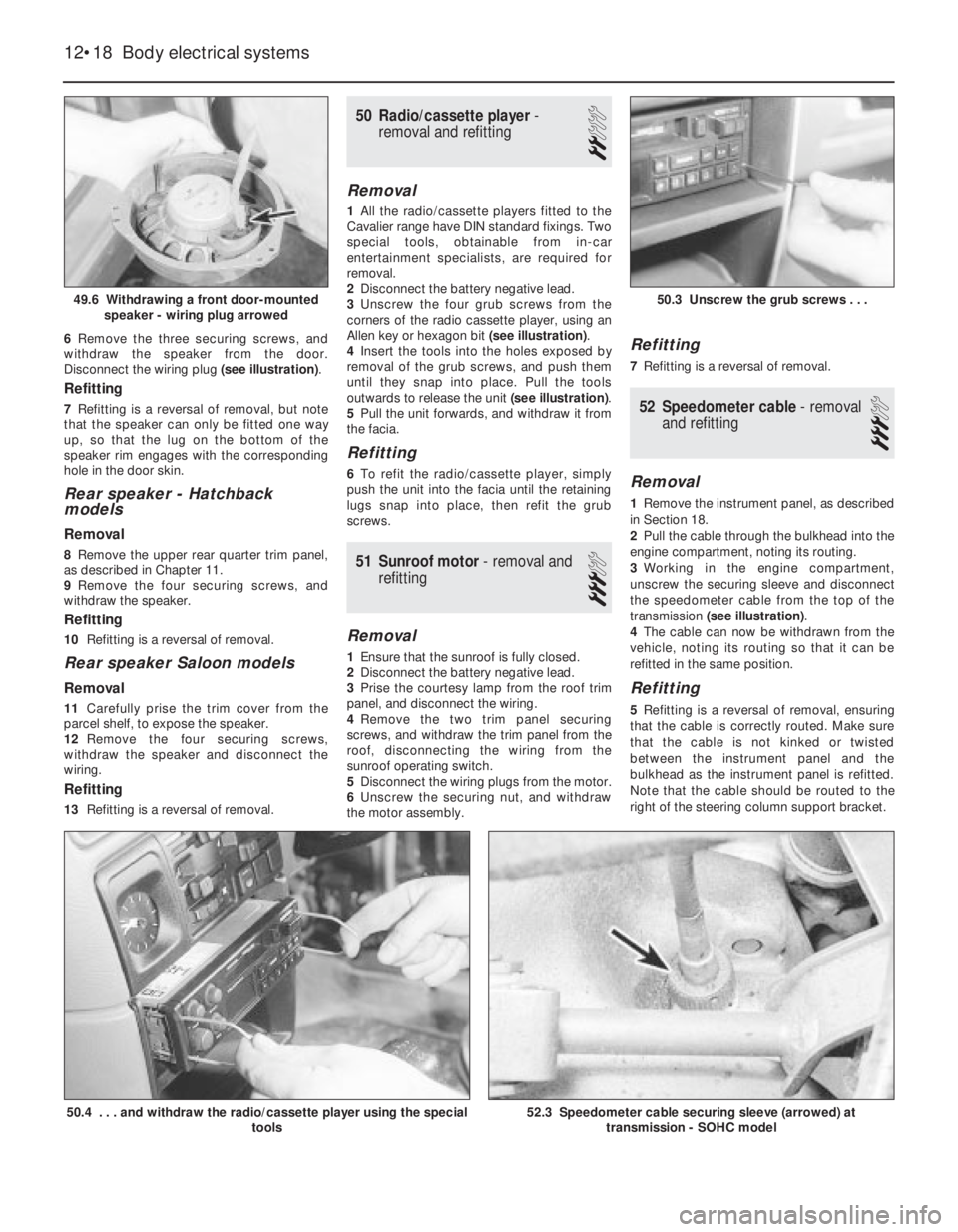
6Remove the three securing screws, and
withdraw the speaker from the door.
Disconnect the wiring plug (see illustration).
Refitting
7Refitting is a reversal of removal, but note
that the speaker can only be fitted one way
up, so that the lug on the bottom of the
speaker rim engages with the corresponding
hole in the door skin.
Rear speaker -Hatchback
models
Removal
8Remove the upper rear quarter trim panel,
as described in Chapter 11.
9Remove the four securing screws, and
withdraw the speaker.
Refitting
10Refitting is a reversal of removal.
Rear speaker Saloon models
Removal
11Carefully prise the trim cover from the
parcel shelf, to expose the speaker.
12Remove the four securing screws,
withdraw the speaker and disconnect the
wiring.
Refitting
13Refitting is a reversal of removal.
50Radio/cassette player -
removal and refitting
2
Removal
1All the radio/cassette players fitted to the
Cavalier range have DIN standard fixings. Two
special tools, obtainable from in-car
entertainment specialists, are required for
removal.
2Disconnect the battery negative lead.
3Unscrew the four grub screws from the
corners of the radio cassette player, using an
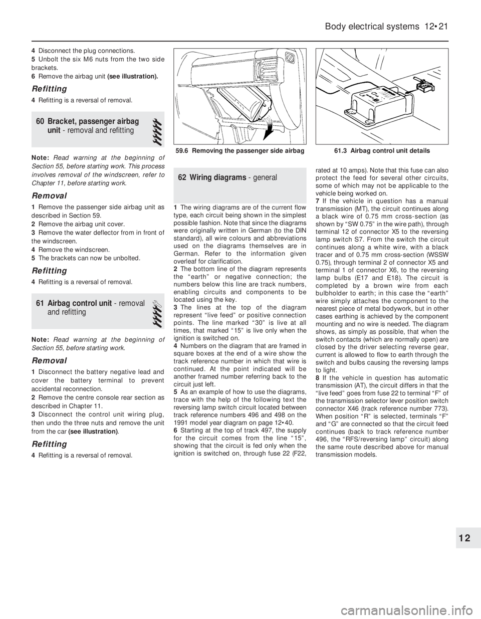
Allen key or hexagon bit (see illustration).
4Insert the tools into the holes exposed by
removal of the grub screws, and push them
until they snap into place. Pull the tools
outwards to release the unit (see illustration).
5Pull the unit forwards, and withdraw it from
the facia.
Refitting
6To refit the radio/cassette player, simply
push the unit into the facia until the retaining
lugs snap into place, then refit the grub
screws.
51Sunroof motor - removal and
refitting
3
Removal
1Ensure that the sunroof is fully closed.
2Disconnect the battery negative lead.
3Prise the courtesy lamp from the roof trim
panel, and disconnect the wiring.
4Remove the two trim panel securing
screws, and withdraw the trim panel from the
roof, disconnecting the wiring from the
sunroof operating switch.
5Disconnect the wiring plugs from the motor.
6Unscrew the securing nut, and withdraw
the motor assembly.
Refitting
7Refitting is a reversal of removal.
52Speedometer cable - removal
and refitting
3
Removal
1Remove the instrument panel, as described
in Section 18.
2Pull the cable through the bulkhead into the
engine compartment, noting its routing.
3Working in the engine compartment,
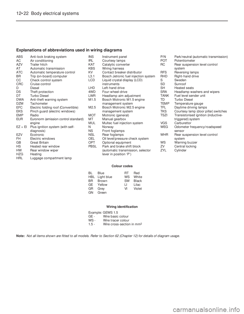
unscrew the securing sleeve and disconnect
the speedometer cable from the top of the
transmission (see illustration).
4The cable can now be withdrawn from the
vehicle, noting its routing so that it can be
refitted in the same position.
Refitting
5Refitting is a reversal of removal, ensuring
that the cable is correctly routed. Make sure
that the cable is not kinked or twisted
between the instrument panel and the
bulkhead as the instrument panel is refitted.
Note that the cable should be routed to the
right of the steering column support bracket.
12•18Body electrical systems
49.6 Withdrawing a front door-mounted
speaker - wiring plug arrowed
50.4 . . . and withdraw the radio/cassette player using the special
tools52.3 Speedometer cable securing sleeve (arrowed) at
transmission - SOHC model
50.3 Unscrew the grub screws . . .
Page 35 of 525
4Disconnect the plug connections.
5Unbolt the six M6 nuts from the two side
brackets.
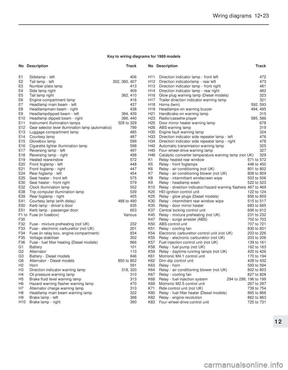
6Remove the airbag unit (see illustration).
Refitting
4Refitting is a reversal of removal.
60Bracket, passenger airbag
unit - removal and refitting
5
Note: Read warning at the beginning of
Section 55, before starting work. This process
involves removal of the windscreen, refer to
Chapter 11, before starting work.
Removal
1Remove the passenger side airbag unit as
described in Section 59.
2Remove the airbag unit cover.
3Remove the water deflector from in front of
the windscreen.
4Remove the windscreen.
5The brackets can now be unbolted.
Refitting
4Refitting is a reversal of removal.
61Airbag control unit - removal
and refitting
4
Note: Read warning at the beginning of
Section 55, before starting work.
Removal
1Disconnect the battery negative lead and
cover the battery terminal to prevent
accidental reconnection.
2Remove the centre console rear section as
described in Chapter 11.
3Disconnect the control unit wiring plug,
then undo the three nuts and remove the unit
from the car (see illustration).
Refitting
4Refitting is a reversal of removal.
62Wiring diagrams -general
1The wiring diagrams are of the current flow
type, each circuit being shown in the simplest
possible fashion. Note that since the diagrams
were originally written in German (to the DIN
standard), all wire colours and abbreviations
used on the diagrams themselves are in
German. Refer to the information given
overleaf for clarification.
2The bottom line of the diagram represents
the “earth” or negative connection; the
numbers below this line are track numbers,
enabling circuits and components to be
located using the key.
3The lines at the top of the diagram
represent “live feed” or positive connection
points. The line marked “30” is live at all
times, that marked “15” is live only when the
ignition is switched on.
4Numbers on the diagram that are framed in
square boxes at the end of a wire show the
track reference number in which that wire is
continued. At the point indicated will be
another framed number referring back to the
circuit just left.
5As an example of how to use the diagrams,
trace with the help of the following text the
reversing lamp switch circuit located between
track reference numbers 496 and 498 on the
1991 model year diagram on page 12•40.
6Starting at the top of track 497, the supply
for the circuit comes from the line “15”,
showing that the circuit is fed only when the
ignition is switched on, through fuse 22 (F22,rated at 10 amps). Note that this fuse can also
protect the feed for several other circuits,
some of which may not be applicable to the
vehicle being worked on.
7If the vehicle in question has a manual
transmission (MT), the circuit continues along
a black wire of 0.75 mm cross-section (as
shown by “SW 0.75” in the wire path), through
terminal 12 of connector X5 to the reversing
lamp switch S7. From the switch the circuit
continues along a white wire, with a black
tracer and of 0.75 mm cross-section (WSSW
0.75), through terminal 2 of connector X5 and
terminal 1 of connector X6, to the reversing
lamp bulbs (E17 and E18). The circuit is
completed by a brown wire from each
bulbholder to earth; in this case the “earth”
wire simply attaches the component to the
nearest piece of metal bodywork, but in other
cases earthing is achieved by the component
mounting and no wire is needed. The diagram
shows, as simply as possible, that when the
switch contacts (which are normally open) are
closed by the driver selecting reverse gear,
current is allowed to flow to earth through the
switch and bulbs causing the reversing lamps
to light.
8If the vehicle in question has automatic
transmission (AT), the circuit differs in that the
“live feed” goes from fuse 22 to terminal “F” of
the transmission selector lever position switch
connector X46 (track reference number 773).
When position “R” is selected, terminals “F”
and “G” are connected so that the circuit feed
continues (back to track reference number
496, the “RFS/reversing lamp” circuit) along
the same route described above for manual
transmission models.
Body electrical systems 12•21
61.3 Airbag control unit details59.6 Removing the passenger side airbag
12
Page 36 of 525
12•22Body electrical systems
Explanations of abbreviations used in wiring diagrams
ABSAnti-lock braking system
ACAir conditioning
AZVTrailer hitch
ATAutomatic transmission
ATCAutomatic temperature control
BRTrip (on-board) computer
CCCheck control system
CRCCruise control
DDiesel
DSTheft protection
DTTurbo Diesel
DWAAnti-theft warning system
DZMTachometer
EFCElectric folding roof (Convertible)
EKSPinch guard (electric windows)
EMPRadio
EUREuronorm (emission control standard)
engine
EZ + ElPlus ignition system (with self-
diagnosis)
EZVEcotronic
FHElectric windows
GBGreat Britain
HSHeated rear window
HWRear window wiper
HZGHeating
HRLLuggage compartment lampINSInstrument panel
IRLCourtesy lamps
KATCatalytic converter
KBSWiring harness
KVContact breaker distributor
L3.1Bosch Jetronic fuel injection system
LCDLiquid crystal display (LCD)
instruments
LHDLeft-hand drive
4WDFour-wheel-drive
LWRHeadlamp aim adjustment
M1.5Bosch Motronic M1.5 engine
management system
M2.5Bosch Motronic M2.5 engine
management system
MOTMotronic (general)
MTManual gearbox
MULMultec fuel injection system
NNorway
NSFront foglamps
NSLRear foglamps
OELOil level/pressure check system
OPTOptional equipment
PBSLPark and brake shift block
(automatic transmission, selector
lever in position ‘P’)P/NPark/neutral (automatic transmission)
POTPotentiometer
RCRear suspension level control
system
RFSReversing lamps
RHDRight-hand drive
SSweden
SDSunroof
SHHeated seats
SRAHeadlamp washers and wipers
TANKFuel level sender unit
TDTurbo Diesel
TEMPTemperature gauge
TFLDaytime driving lamps
TKSCourtesy lamp (door pillar) switches
TSZITransistorised ignition (inductive-
triggered) system
VGSCarburettor
WEGOdometer frequency/roadspeed
sensor
WHRRear suspension level control
system
WSWarning buzzer
ZVCentral locking
ZYLCylinder
Colour codes
BLBlue
HBLLight blue
BRBrown
GEYellow
GRGrey
GNGreenRTRed
WSWhite
SWBlack
LILilac
VIViolet
Wiring identification
Example: GEWS 1.5
GE -Wire basic colour
WS -Wire tracer colour
1.5 -Wire cross-section in mm
2
Note: Not all items shown are fitted to all models. Refer to Section 62 (Chapter 12) for details of diagram usage.
Page 37 of 525
Wiring diagrams 12•23
12
Key to wiring diagrams for 1989 models
E1Sidelamp - left406
E2Tail lamp -left302, 380, 407
E3Number plate lamp413
E4Side lamp right409
E5Tail lamp right382, 410
E6Engine compartment lamp416
E7Headlamp main beam - left437
E8Headlampmain beam - right438
E9Headlampdipped beam - left384, 439
E10Headlamp dipped beam - right386, 440
E11Instrument illumination lamps328 to 329
E12Gear selector lever illumination lamp (automatics)799
E13Luggage compartment lamp485
E14Courtesy lamp487
E15Glovebox lamp599
E16Cigarette lighter illumination lamp598
E17Reversing lamp - left497
E18Reversing lamp - right498
E19Heated rearwindow572
E20Front foglamp -left448
E21Front foglamp - right447
E24Rear foglamp - left454
E25Seat heater -front left575
E30Seat heater - front right579
E32Clock illumination lamp552
E38Trip computer illumination lamp539
E39Rear foglamp - right455
E41Courtesy lamp (with delay)488 to 490
E50Kerb lamp - driver’s door635
E51Kerb lamp - passenger door653
F1 toFuse (in fusebox)Various
F30
F32Fuse - mixture preheating (not UK)232
F33Fuse - electronic carburettor (not UK)201
F34Fuse (in relay box, engine compartment)834
F35Voltage stabiliser302
F36Fuse - fuel filter heating (Diesel models)866
G1Battery101
G2Alternator110
G3Battery - Diesel models846
G6Alternator - Diesel models850 to 852
H2Horn591
H3Direction indicator warning lamp318, 320
H4Oil pressure warning lamp310
H5Brake fluid level warning lamp313
H6Hazard warning flasher warning lamp470
H7Alternator charge warning lamp310
H8Headlamp main beam warning lamp322
H9Brake lamp - left388
H10Brake lamp - right390H11Direction indicator lamp - front left472
H12Direction indicatorlamp - rear left473
H13Direction indicator lamp - front right481
H14Direction indicator lamp - rear right482
H16Glow plug warning lamp (Diesel models)323
H17Trailer direction indicator warning lamp321
H18Horns (twin)592, 593
H19Headlamps-on warning buzzer494, 495
H21Handbrake-on warning lamp315
H23Radio/cassette player585, 586
H25Door mirror heater warning lamp678
H26ABS warning lamp319
H30Engine fault warning lamp324
H33Direction indicator side repeater lamp - left476
H34Direction indicator side repeater lamp - right478
H42Automatic transmission warning lamp325
H45Four-wheel-drive warning lamp327
H46Catalytic converter temperature warning lamp (not UK)329
K1Relay-heated rear window571 to 572
K5Relay - front foglamps448 to 450
K6Relay - air conditioning (not UK)801 to 802
K7Relay - air conditioning blower (not UK)808 to 809
K8Relay - intermittent windscreen wipe503 to 506
K9Relay - headlamp wash522 to 523
K10Relay - direction indicator/hazard warning flashers467 to 469
K20HEI ignition control unit122 to 124
K25Relay - glow plugs (Diesel models)856 to 859
K30Relay - intermittent rear window wipe515 to 517
K35Relay - door mirror heater683 to 685
K37Central locking control unit606 to 612
K45Relay - mixture preheating (not UK)231 to 232
K47Relay - surge arrester (ABS)702 to 703
K50ABS control unit707 to 721
K51Relay - cooling fan830 to 831
K54Electronic carburettor control unit (not UK)203 to 226
K55Relay - electronic carburettor (not UK)203 to 206
K57Fuel injection control unit (not UK)139 to 161
K58Relay -fuel pump (not UK)162 to 163
K59Relay - daytime running lamps (not UK)420 to 426
K61Motronic M4.1 control unit170 to 194
K62Dim-dip control unit428 to 432
K63Relay - horn593 to 594
K64Relay - air conditioning blower (not UK)802 to 803
K67Relay -cooling fan827 to 828
K68Relay -fuel injection system294 to 299, 196 to 199
K69Motronic M2.5 control unit267 to 297
K71Ride control unit (not UK)739 to 754
K80Relay -fuel filter heater (Diesel models)865 to 866
K82Relay - engine revolution862 to 863
K83Four-wheel-drive control unit725 to 731 NoDescriptionTrackNoDescriptionTrack