1988 OPEL VECTRA jacking
[x] Cancel search: jackingPage 116 of 525
4Certain models may have additional
underbody shields and splashguards fitted,
which may be attached to the wheel arch liners.
32Engine undershield (DOHC
models) - removal and
refitting
2
Removal
1Apply the handbrake, then jack up the front
of the vehicle, and support on axle stands
(see “Jacking and Vehicle Support”).
2Extract the two securing screws, and
remove the oil filter access panel.
3Working around the edges of the splash
shield, remove the self tapping screws that
secure the shield to the body, noting that
some of the screws also secure the wheel
arch liners.
4With the help of an assistant, pull the shield
from the vehicle, and place it to one side to
avoid damage.
Refitting
5Refitting is a reversal of removal.
33Fuel filler flap -removal and
refitting
2
Removal
1Open the flap for access to the four screws
securing the flap to the rear wing.2Remove the securing screws, and withdraw
the flap.
Refitting
3Refitting is a reversal of removal.
34Sunroof components -
removal and refitting
4
Note:The sunroof is a complex piece of
equipment consisting of a large number of
components. It is strongly recommended that
the sunroof mechanism is not disturbed unless
necessary. If the sunroof mechanism is faulty, or
requires overhaul, consult a dealer for advice.
Glass panel
Removal
1Push the sunshade fully rearwards, and
open the glass panel halfway.
2Extract the four securing screws from the
front edge of the guide rail plastic surround,
and withdraw the surround down through the
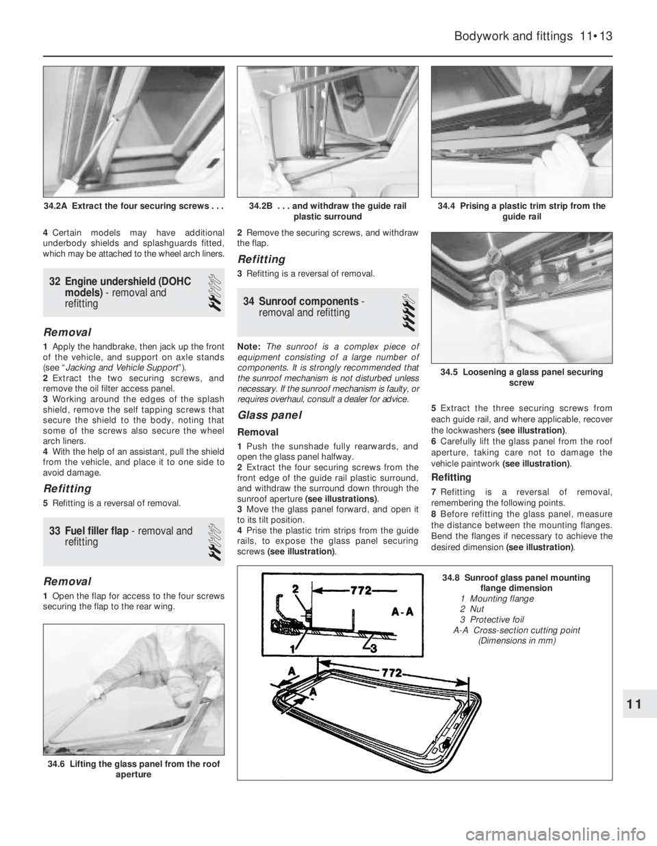
sunroof aperture (see illustrations).
3Move the glass panel forward, and open it
to its tilt position.
4Prise the plastic trim strips from the guide
rails, to expose the glass panel securing
screws (see illustration).5Extract the three securing screws from
each guide rail, and where applicable, recover
the lockwashers (see illustration).
6Carefully lift the glass panel from the roof
aperture, taking care not to damage the
vehicle paintwork (see illustration).
Refitting
7Refitting is a reversal of removal,
remembering the following points.
8Before refitting the glass panel, measure
the distance between the mounting flanges.
Bend the flanges if necessary to achieve the
desired dimension (see illustration).
Bodywork and fittings 11•13
34.4 Prising a plastic trim strip from the
guide rail
34.6 Lifting the glass panel from the roof
aperture
34.5 Loosening a glass panel securing
screw
34.2B . . . and withdraw the guide rail
plastic surround34.2A Extract the four securing screws . . .
11
34.8 Sunroof glass panel mounting
flange dimension
1 Mounting flange
2 Nut
3 Protective foil
A-A Cross-section cutting point
(Dimensions in mm)
Page 127 of 525
2Exhaust gas recirculation
(EGR) system - general
The system reintroduces small amounts of
exhaust gas into the combustion cycle to
reduce the generation of oxides of nitrogen
(NOx).
On C16 NZ, C16 NZ2 and C18 NZ engines,
the volume of exhaust gas reintroduced is
governed by manifold vacuum, through the
EGR valve mounted on the inlet manifold.
When the valve is opened small amounts of
exhaust gas are allowed to enter the inlet
tract, passing through ports in the cylinder
head.
On X16 SZ engines the EGR valve is
operated by an EGR module, mounted on the
left-hand side of the engine compartment
behind the battery. This module amplifies
signals received from the fuel system ECU
and operates the EGR valve electronically
providing precise control of exhaust gas
recirculation under all engine conditions.
3EGR valve (Multec system
models) - testing, removal and
refitting
2
Testing
1On C16 NZ, C16 NZ2 and C18 NZ engines,
it is recommended that the system is checked
annually, by checking the movement of the
valve’s diaphragm carrier plate as follows.
Note that the carrier plate is visible only
through the apertures in the underside of the
valve, so a battery-operated torch and small
mirror may be useful. On X16 SZ engines,
Vauxhall test equipment is necessary to check
the EGR system.
2With the engine fully warmed up to normal
operating temperature and idling, briefly open
and close the throttle. The carrier plate should
move upwards as the manifold vacuum
changes. When the engine is idling smoothly
again, press the carrier plate upwards (do this
very carefully, so that the plate is not distorted or
the diaphragm damaged). The idle speed should
drop significantly (approximately 100 rpm).
3If the valve does not respond as described,
it must be cleaned.
Removal
4Pull off the hose from the valve, then unbolt
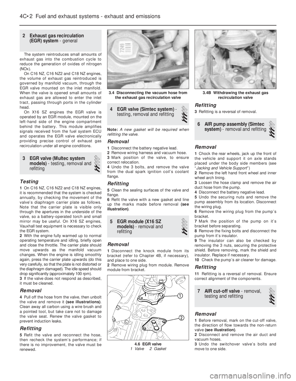
the valve and remove it (see illustrations).
Clean away all carbon using a wire brush and
a pointed tool, but take care not to damage
the valve seat. Renew the valve gasket to
prevent induction leaks.
Refitting
5Refit the valve and reconnect the hose,
then recheck the system’s performance; if
there is no improvement, the valve must be
renewed.
4EGR valve (Simtec system) -
testing, removal and refitting
3
Note: A new gasket will be required when
refitting the valve.
Removal
1Disconnect the battery negative lead.
2Remove wiring harness and vacuum hose.
3Mark position of the valve, to ensure
correct relocation.
4Undo the 3 bolts, and remove the valve
from the dual spark ignition coil’s coolant
flange.
Refitting
5Clean the sealing surfaces of the valve and
flange.
6Refit the valve with a new gasket and line
up the marks made before removal (see
illustration).
5EGR module (X16 SZ
models) - removal and
refitting
2
Removal
1Disconnect the knock module from its
bracket (refer to Chapter 4B, if necessary),
and place to one side.
2Remove wiring plug from module. Remove
module from bracket.
Refitting
3Refitting is a reversal of removal.
6AIR pump assembly (Simtec
system) - removal and refitting
3
Removal
1Chock the rear wheels, jack up the front of
the vehicle and support it on axle stands
placed under the body side members (see
“Jacking and Vehicle Support”)
2Remove the left hand front wheel and inner
wheel arch lining.
3Loosen the hose clamp and remove the air
duct hose from the pump.
4Disconnect the battery negative lead.
5Undo the securing nuts and remove the
pump assembly from its location. Disconnect
the wiring plug.
6Remove the wiring plug from the pump’s
bracket.
7Mark the position of the pump on it’s
bracket before separating.
8Remove the fixing bolts and disconnect the
pump from it’s insulator.
9The insulator can also be checked by
removing the 3 nuts, securing the protective
shield. Before removing, mark the shield and
insulator. Replace if necessary.
10Check the pump’s air cleaner for damage.
Refitting
11Refitting is a reversal of removal. Ensure
correct alignment of the components.
7AIR cut-off valve - removal,
testing and refitting
3
Removal
1Before removal, mark on the cut-off valve,
the direction of flow towards the non-return
valve (see illustration).
2Disconnect and remove the air duct and
vacuum hoses.
3Undo the switchover valve’s bolts and
move to one side.
4C•2Fuel and exhaust systems - exhaust and emissions
3.4 Disconnecting the vacuum hose from
the exhaust gas recirculation valve
4.6 EGR valve
1 Valve 2 Gasket
3.4B Withdrawing the exhaust gas
recirculation valve
Page 129 of 525
b)Always keep the ignition and fuel systems
well maintained according to the
manufacturers schedule (see “Routine
maintenance” and the relevant Chapter).
In particular, ensure that the air cleaner
filter element, the fuel filter and the spark
plugs are renewed at the correct intervals.
If the inlet air/fuel mixture is allowed to
become too rich due to neglect, the
unburned surplus will enter and burn in
the catalytic converter, overheating the
element and eventually destroying the
converter.
c)If the engine develops a misfire, do not
drive the vehicle at all (or at least as little
as possible) until the fault is cured. The
misfire will allow unburned fuel to enter
the converter, which will result in its
overheating, as noted above.
d)The engine control indicator (the outline
of an engine with a lightning symbol
superimposed), will light when the ignition
is switched on and the engine is started,
then it will go out. While it may light briefly
while the engine is running, it should go
out again immediately and stays unlit. If it
lights and stays on while the engine is
running, seek the advice of a Vauxhall
dealer as soon as possible. A fault has
occurred in the fuel injection/ignition
system that, apart from increasing fuel
consumption and impairing the engine’s
performance, may damage the catalytic
converter.
e)DO NOT push or tow-start the vehicle.
This will soak the catalytic converter in
unburned fuel causing it to overheat when
the engine does start see (b) above.
f)DO NOT switch off the ignition at high
engine speeds. If the ignition is switched
off at anything above idle speed,
unburned fuel will enter the (very hot)
catalytic converter, with the possible risk
of its igniting on the element and
damaging the converter.
g)DO NOT use fuel or engine oil additives.
These may contain substances harmful to
the catalytic converter.
h)DO NOT continue to use the vehicle if the
engine burns oil to the extent of leaving a
visible trail of blue smoke. The unburned
carbon deposits will clog the converter
passages and reduce its efficiency; in
severe cases the element will overheat.
i)Remember that the catalytic converter
operates at very high temperatures hence
the heat shields on the vehicle’s under-
body and the casing will become hot
enough to ignite combustible materials
that brush against it. DO NOT, therefore,
park the vehicle in dry undergrowth, over
long grass or over piles of dead leaves.
j)Remember that the catalytic converter is
FRAGlLE. Do not strike it with tools during
servicing work. Take great care when
working on the exhaust system. Ensure
that the converter is well clear of any
jacks or other lifting gear used to raise thevehicle. Do not drive the vehicle over
rough ground, road humps, etc., in such a
way as to ground the exhaust system.
k)In some cases, particularly when the
vehicle is new and/or is used for
stop/start driving, a sulphurous smell (like
that of rotten eggs) may be noticed from
the exhaust. This is common to many
catalytic converter-equipped vehicles and
seems to be due to the small amount of
sulphur found in some petrol’s reacting
with hydrogen in the exhaust to produce
hydrogen sulphide (CS) gas. While this
gas is toxic, it is not produced in sufficient
amounts to be a problem. Once the
vehicle has covered a few thousand miles
the problem should disappear. In the
meanwhile a change of driving style or of
the brand of petrol may effect a solution.
l)The catalytic converter, used on a
well-maintained and well-driven vehicle,
should last for between 50 000 and 100
000 miles. From this point on, careful
checks should be made at all specified
service intervals of the CO level to ensure
that the converter is still operating
efficiently. If the converter is no longer
effective it must be renewed.
11Carbon canister - removal
and refitting
3
Removal
1Apply the handbrake, then jack up the front
of the vehicle, and support securely on axle
stands placed under the body side members
(see “Jacking and Vehicle Support”).
2Remove the front right hand wheel and
wheel arch liner.
3Note the hose and pipe connections to the
canister, or label them, to ensure that they are
reconnected to their original unions, then
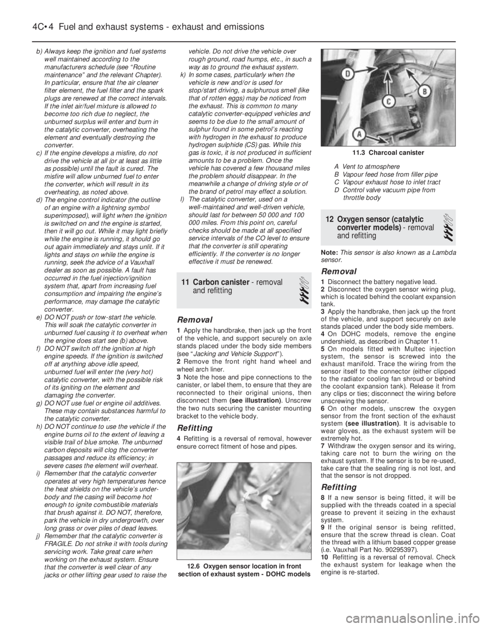
disconnect them (see illustration). Unscrew
the two nuts securing the canister mounting
bracket to the vehicle body.
Refitting
4Refitting is a reversal of removal, however
ensure correct fitment of hose and pipes.
12Oxygen sensor (catalytic
converter models) - removal
and refitting
3
Note: This sensor is also known as a Lambda
sensor.
Removal
1Disconnect the battery negative lead.
2Disconnect the oxygen sensor wiring plug,
which is located behind the coolant expansion
tank.
3Apply the handbrake, then jack up the front
of the vehicle, and support securely on axle
stands placed under the body side members.
4On DOHC models, remove the engine
undershield, as described in Chapter 11.
5On models fitted with Multec injection
system, the sensor is screwed into the
exhaust manifold. Trace the wiring from the
sensor itself to the connector (either clipped
to the radiator cooling fan shroud or behind
the coolant expansion tank). Release it from
any clips or ties; disconnect the wiring before
unscrewing the sensor.
6On other models, unscrew the oxygen
sensor from the front section of the exhaust
system (see illustration). It is advisable to
wear gloves, as the exhaust system will be
extremely hot.
7Withdraw the oxygen sensor and its wiring,
taking care not to burn the wiring on the
exhaust system. If the sensor is to be re-used,
take care that the sealing ring is not lost, and
that the sensor is not dropped.
Refitting
8If a new sensor is being fitted, it will be
supplied with the threads coated in a special
grease to prevent it seizing in the exhaust
system.
9If the original sensor is being refitted,
ensure that the screw thread is clean. Coat
the thread with a lithium based copper grease
(i.e. Vauxhall Part No. 90295397).
10Refitting is a reversal of removal. Check
the exhaust system for leakage when the
engine is re-started.
4C•4Fuel and exhaust systems - exhaust and emissions
12.6 Oxygen sensor location in front
section of exhaust system - DOHC models
11.3 Charcoal canister
A Vent to atmosphere
B Vapour feed hose from filler pipe
C Vapour exhaust hose to inlet tract
D Control valve vacuum pipe from
throttle body
Page 130 of 525
13Exhaust manifold - removal
and refitting
3
Note:New manifold-to-cylinder head, and
manifold-to-downpipe, gaskets must be used
on refitting. Exhaust manifolds on DOHC
models are of tubular design, which form part
of the front section of the exhaust.
Removal
1Disconnect the battery negative lead.
2Disconnect the HT leads from the spark
plugs, if necessary labelling them to ensure
refitting to the correct cylinders.
3Loosen the clamp screw and disconnect
the air cleaner hot air tube from the shroud on
the manifold, if fitted. Remove the securing
screws and withdraw the hot air shroud from
the manifold.
4Working under the manifold, unscrew and
remove the four bolts securing the exhaust
downpipe to the manifold.
5If fitted, disconnect the oxygen sensor
wiring
6Separate the downpipe from the manifold,
and support with wire or string. Do not allow
the front section of the exhaust system to hang
under its own weight. Recover the gasket.
7Unscrew the securing nuts, and withdraw
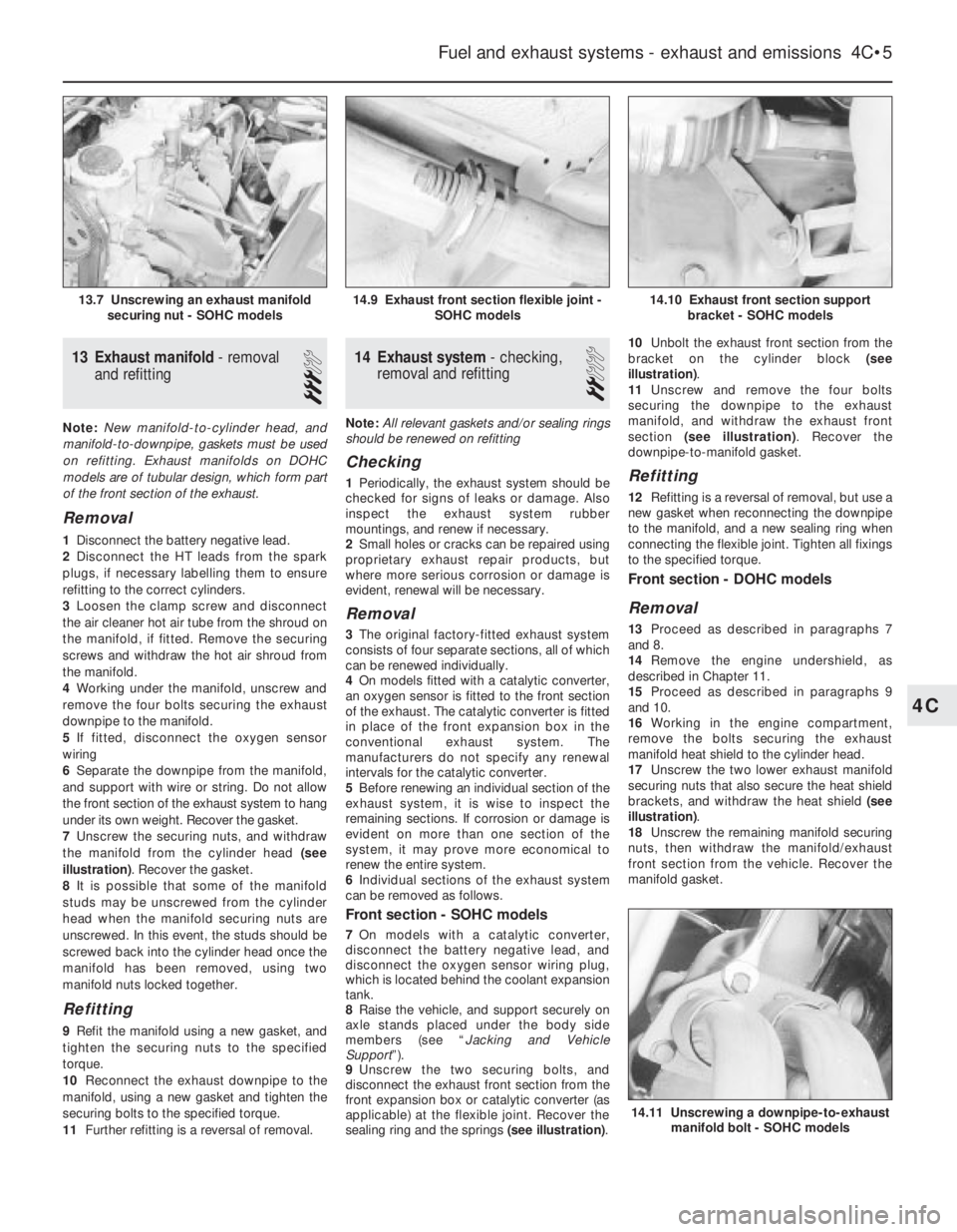
the manifold from the cylinder head (see
illustration). Recover the gasket.
8It is possible that some of the manifold
studs may be unscrewed from the cylinder
head when the manifold securing nuts are
unscrewed. In this event, the studs should be
screwed back into the cylinder head once the
manifold has been removed, using two
manifold nuts locked together.
Refitting
9Refit the manifold using a new gasket, and
tighten the securing nuts to the specified
torque.
10Reconnect the exhaust downpipe to the
manifold, using a new gasket and tighten the
securing bolts to the specified torque.
11Further refitting is a reversal of removal.
14Exhaust system - checking,
removal and refitting
2
Note: All relevant gaskets and/or sealing rings
should be renewed on refitting
Checking
1Periodically, the exhaust system should be
checked for signs of leaks or damage. Also
inspect the exhaust system rubber
mountings, and renew if necessary.
2Small holes or cracks can be repaired using
proprietary exhaust repair products, but
where more serious corrosion or damage is
evident, renewal will be necessary.
Removal
3The original factory-fitted exhaust system
consists of four separate sections, all of which
can be renewed individually.
4On models fitted with a catalytic converter,
an oxygen sensor is fitted to the front section
of the exhaust. The catalytic converter is fitted
in place of the front expansion box in the
conventional exhaust system. The
manufacturers do not specify any renewal
intervals for the catalytic converter.
5Before renewing an individual section of the
exhaust system, it is wise to inspect the
remaining sections. If corrosion or damage is
evident on more than one section of the
system, it may prove more economical to
renew the entire system.
6Individual sections of the exhaust system
can be removed as follows.
Front section - SOHC models
7On models with a catalytic converter,
disconnect the battery negative lead, and
disconnect the oxygen sensor wiring plug,
which is located behind the coolant expansion
tank.
8Raise the vehicle, and support securely on
axle stands placed under the body side
members (see “Jacking and Vehicle
Support”).
9Unscrew the two securing bolts, and
disconnect the exhaust front section from the
front expansion box or catalytic converter (as
applicable) at the flexible joint. Recover the
sealing ring and the springs (see illustration).10Unbolt the exhaust front section from the
bracket on the cylinder block (see
illustration).
11Unscrew and remove the four bolts
securing the downpipe to the exhaust
manifold, and withdraw the exhaust front
section (see illustration). Recover the
downpipe-to-manifold gasket.
Refitting
12Refitting is a reversal of removal, but use a
new gasket when reconnecting the downpipe
to the manifold, and a new sealing ring when
connecting the flexible joint. Tighten all fixings
to the specified torque.
Front section - DOHC models
Removal
13Proceed as described in paragraphs 7
and 8.
14Remove the engine undershield, as
described in Chapter 11.
15Proceed as described in paragraphs 9
and 10.
16Working in the engine compartment,
remove the bolts securing the exhaust
manifold heat shield to the cylinder head.
17Unscrew the two lower exhaust manifold
securing nuts that also secure the heat shield
brackets, and withdraw the heat shield (see
illustration).
18Unscrew the remaining manifold securing
nuts, then withdraw the manifold/exhaust
front section from the vehicle. Recover the
manifold gasket.
Fuel and exhaust systems - exhaust and emissions 4C•5
14.10 Exhaust front section support
bracket - SOHC models
14.11 Unscrewing a downpipe-to-exhaust
manifold bolt - SOHC models
14.9 Exhaust front section flexible joint -
SOHC models13.7 Unscrewing an exhaust manifold
securing nut - SOHC models
4C
Page 135 of 525
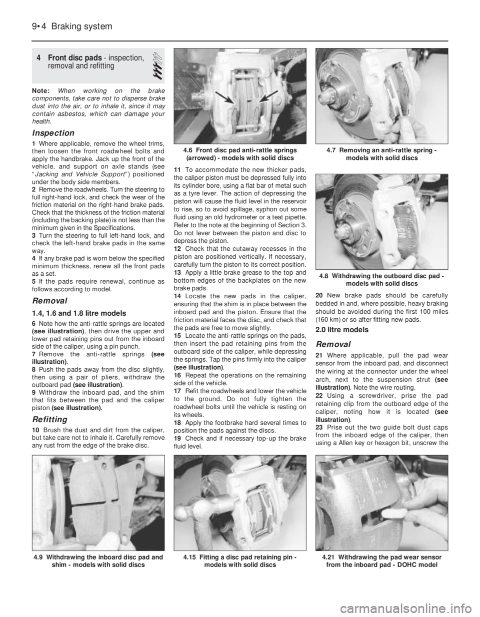
4Front disc pads - inspection,
removal and refitting
3
Note: When working on the brake
components, take care not to disperse brake
dust into the air, or to inhale it, since it may
contain asbestos, which can damage your
health.
Inspection
1Where applicable, remove the wheel trims,
then loosen the front roadwheel bolts and
apply the handbrake. Jack up the front of the
vehicle, and support on axle stands (see
“Jacking and Vehicle Support”) positioned
under the body side members.
2Remove the roadwheels. Turn the steering to
full right-hand lock, and check the wear of the
friction material on the right-hand brake pads.
Check that the thickness of the friction material
(including the backing plate) is not less than the
minimum given in the Specifications.
3Turn the steering to full left-hand lock, and
check the left-hand brake pads in the same
way.
4If any brake pad is worn below the specified
minimum thickness, renew all the front pads
as a set.
5If the pads require renewal, continue as
follows according to model.
Removal
1.4, 1.6 and 1.8 litre models
6Note how the anti-rattle springs are located
(see illustration), then drive the upper and
lower pad retaining pins out from the inboard
side of the caliper, using a pin punch.
7Remove the anti-rattle springs (see
illustration).
8Push the pads away from the disc slightly,
then using a pair of pliers, withdraw the
outboard pad (see illustration).
9Withdraw the inboard pad, and the shim
that fits between the pad and the caliper
piston (see illustration).
Refitting
10Brush the dust and dirt from the caliper,
but take care not to inhale it. Carefully remove
any rust from the edge of the brake disc.11To accommodate the new thicker pads,
the caliper piston must be depressed fully into
its cylinder bore, using a flat bar of metal such
as a tyre lever. The action of depressing the
piston will cause the fluid level in the reservoir
to rise, so to avoid spillage, syphon out some
fluid using an old hydrometer or a teat pipette.
Refer to the note at the beginning of Section 3.
Do not lever between the piston and disc to
depress the piston.
12Check that the cutaway recesses in the
piston are positioned vertically. If necessary,
carefully turn the piston to its correct position.
13Apply a little brake grease to the top and
bottom edges of the backplates on the new
brake pads.
14Locate the new pads in the caliper,
ensuring that the shim is in place between the
inboard pad and the piston. Ensure that the
friction material faces the disc, and check that
the pads are free to move slightly.
15Locate the anti-rattle springs on the pads,
then insert the pad retaining pins from the
outboard side of the caliper, while depressing
the springs. Tap the pins firmly into the caliper
(see illustration).
16Repeat the operations on the remaining
side of the vehicle.
17Refit the roadwheels and lower the vehicle
to the ground. Do not fully tighten the
roadwheel bolts until the vehicle is resting on
its wheels.
18Apply the footbrake hard several times to
position the pads against the discs.
19Check and if necessary top-up the brake
fluid level.20New brake pads should be carefully
bedded in and, where possible, heavy braking
should be avoided during the first 100 miles
(160 km) or so after fitting new pads.
2.0 litre models
Removal
21Where applicable, pull the pad wear
sensor from the inboard pad, and disconnect
the wiring at the connector under the wheel
arch, next to the suspension strut (see
illustration). Note the wire routing.
22Using a screwdriver, prise the pad
retaining clip from the outboard edge of the
caliper, noting how it is located (see
illustration).
23Prise out the two guide bolt dust caps
from the inboard edge of the caliper, then
using a Allen key or hexagon bit, unscrew the
9•4Braking system
4.6 Front disc pad anti-rattle springs
(arrowed) - models with solid discs
4.8 Withdrawing the outboard disc pad -
models with solid discs
4.21 Withdrawing the pad wear sensor
from the inboard pad - DOHC model4.15 Fitting a disc pad retaining pin -
models with solid discs4.9 Withdrawing the inboard disc pad and
shim - models with solid discs
4.7 Removing an anti-rattle spring -
models with solid discs
Page 136 of 525
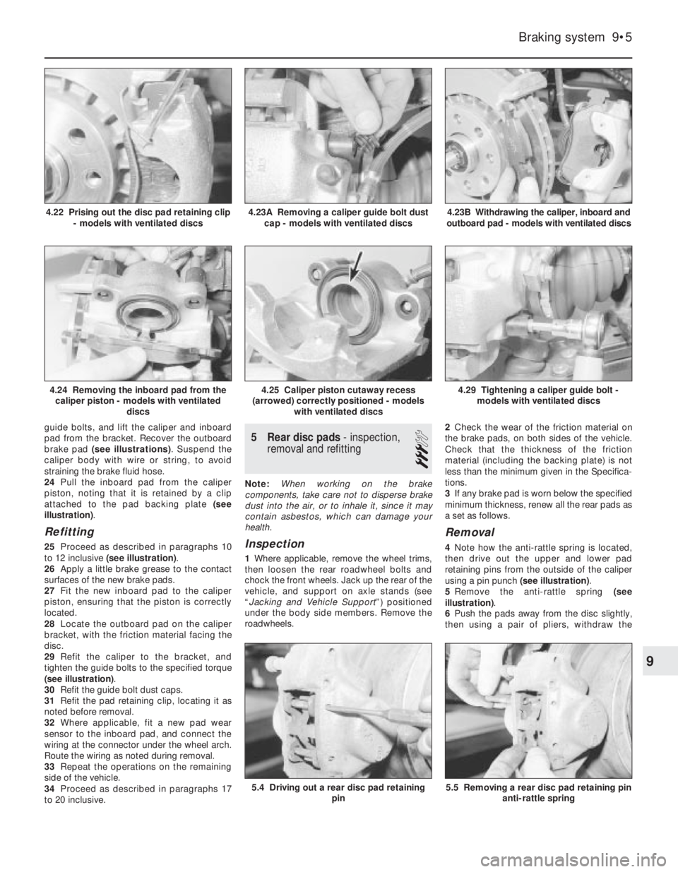
guide bolts, and lift the caliper and inboard
pad from the bracket. Recover the outboard
brake pad (see illustrations). Suspend the
caliper body with wire or string, to avoid
straining the brake fluid hose.
24Pull the inboard pad from the caliper
piston, noting that it is retained by a clip
attached to the pad backing plate (see
illustration).
Refitting
25Proceed as described in paragraphs 10
to 12 inclusive (see illustration).
26Apply a little brake grease to the contact
surfaces of the new brake pads.
27Fit the new inboard pad to the caliper
piston, ensuring that the piston is correctly
located.
28Locate the outboard pad on the caliper
bracket, with the friction material facing the
disc.
29Refit the caliper to the bracket, and
tighten the guide bolts to the specified torque
(see illustration).
30Refit the guide bolt dust caps.
31Refit the pad retaining clip, locating it as
noted before removal.
32Where applicable, fit a new pad wear
sensor to the inboard pad, and connect the
wiring at the connector under the wheel arch.
Route the wiring as noted during removal.
33Repeat the operations on the remaining
side of the vehicle.
34Proceed as described in paragraphs 17
to 20 inclusive.
5Rear disc pads - inspection,
removal and refitting
3
Note: When working on the brake
components, take care not to disperse brake
dust into the air, or to inhale it, since it may
contain asbestos, which can damage your
health.
Inspection
1Where applicable, remove the wheel trims,
then loosen the rear roadwheel bolts and
chock the front wheels. Jack up the rear of the
vehicle, and support on axle stands (see
“Jacking and Vehicle Support”) positioned
under the body side members. Remove the
roadwheels.2Check the wear of the friction material on
the brake pads, on both sides of the vehicle.
Check that the thickness of the friction
material (including the backing plate) is not
less than the minimum given in the Specifica-
tions.
3If any brake pad is worn below the specified
minimum thickness, renew all the rear pads as
a set as follows.
Removal
4Note how the anti-rattle spring is located,
then drive out the upper and lower pad
retaining pins from the outside of the caliper
using a pin punch (see illustration).
5Remove the anti-rattle spring (see
illustration).
6Push the pads away from the disc slightly,
then using a pair of pliers, withdraw the
Braking system 9•5
4.23B Withdrawing the caliper, inboard and
outboard pad - models with ventilated discs
5.5 Removing a rear disc pad retaining pin
anti-rattle spring5.4 Driving out a rear disc pad retaining
pin
4.29 Tightening a caliper guide bolt -
models with ventilated discs4.25 Caliper piston cutaway recess
(arrowed) correctly positioned - models
with ventilated discs4.24 Removing the inboard pad from the
caliper piston - models with ventilated
discs
4.23A Removing a caliper guide bolt dust
cap - models with ventilated discs4.22 Prising out the disc pad retaining clip
- models with ventilated discs
9
Page 137 of 525
outboard pad and anti-squeal shim that fits
between the pad and the caliper body.
7Withdraw the inboard pad and anti-squeal
shim.
Refitting
8Proceed as described in Section 4,
paragraphs 10 and 11.
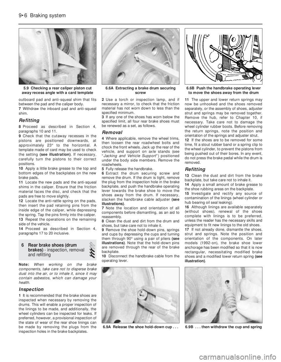
9Check that the cutaway recesses in the
pistons are positioned downwards, at
approximately 23°to the horizontal. A
template made of card may be used to check
the setting (see illustration). If necessary,
carefully turn the pistons to their correct
positions.
10Apply a little brake grease to the top and
bottom edges of the backplates on the new
brake pads.
11Locate the new pads and the anti-squeal
shims in the caliper. Ensure that the friction
material faces the disc, and check that the
pads are free to move slightly.
12Locate the anti-rattle spring on the pads,
then insert the pad retaining pins from the
inside edge of the caliper, while depressing
the spring. Tap the pins firmly into the caliper.
13Repeat the operations on the remaining
side of the vehicle.
14Proceed as described in Section 4,
paragraphs 17 to 20 inclusive.
6Rear brake shoes (drum
brakes) - inspection, removal
and refitting
3
Note: When working on the brake
components, take care not to disperse brake
dust into the air, or to inhale it, since it may
contain asbestos, which can damage your
health.
Inspection
1It is recommended that the brake shoes are
inspected when necessary by removing the
drums. This will enable a proper inspection of
the linings to be made, and additionally, the
wheel cylinders can be inspected for leaks. If
preferred, however, a provisional inspection of
the state of wear of the rear shoe linings can
be made by removing the plugs from the
inspection holes in the brake backplates.2Use a torch or inspection lamp, and if
necessary a mirror, to check that the friction
material has not worn down to less than the
specified minimum.
3If any one of the shoes has worn below the
specified limit, all four rear brake shoes must
be renewed as a set, as follows.
Removal
4Where applicable, remove the wheel trims,
then loosen the rear roadwheel bolts and
chock the front wheels. Jack up the rear of the
vehicle, and support on axle stands (see
“Jacking and Vehicle Support”) positioned
under the body side members. Remove the
roadwheels.
5Fully release the handbrake.
6Extract the drum securing screw and
remove the drum. If the drum is tight, remove
the plug from the inspection hole in the brake
backplate, and push the handbrake operating
lever towards the brake shoe to move the
shoes away from the drum. If necessary,
slacken the handbrake cable adjuster (see
illustrations).
7Note the location and orientation of all
components before dismantling, as an aid to
reassembly.
8Clean the dust and dirt from the drum and
shoes, but take care not to inhale it.
9Remove the shoe hold-down pins, springs
and cups by depressing the cups and turning
them through 90°using a pair of pliers (see
illustrations). Note that the hold-down pins
are removed through the rear of the brake
backplate.
10Disconnect the handbrake cable from the
operating lever.11The upper and lower return springs may
now be unhooked and the shoes removed
separately, or the assembly of shoes, adjuster
strut and springs may be removed together.
Remove the hub, refer to Chapter 10, if
necessary. Take care not to damage the
wheel cylinder rubber boots. Before removing
the return springs, note the position and
orientation of the springs and adjuster strut.
12If the shoes are to be removed for some
time, fit a stout rubber band or a spring clip to
the wheel cylinder, to prevent the pistons from
being pushed out of their bores. In any event,
do not press the brake pedal while the drum is
removed.
Refitting
13Clean the dust and dirt from the brake
backplate, but take care not to inhale it.
14Apply a small amount of brake grease to
the shoe rubbing areas on the backplate.
15Investigate and rectify any source of
contamination of the linings (wheel cylinder or
hub bearing oil seal leaking).
16Although linings are available separately
(without shoes), renewal of the shoes
complete with linings is to be preferred,
unless the reader has the necessary skills and
equipment to fit new linings to the old shoes.
17If not already done, dismantle the shoes,
strut and springs. Note the position and
orientation of the components. On later
models (1992-on), the brake shoe lower
anchorage has been modified so that it is now
rectangular, necessitating modified brake
shoes and a modified lower return spring (see
illustration).
9•6Braking system
5.9 Checking a rear caliper piston cut
away recess angle with a card template6.6B Push the handbrake operating lever
to move the shoes away from the drum
6.9B . . . then withdraw the cup and spring6.9A Release the shoe hold-down cup . . .
6.6A Extracting a brake drum securing
screw
Page 139 of 525
5If any one of the shoes has worn below the
specified limit, all four handbrake shoes must
be renewed as a set, as follows.
SOHC models
Removal
6Clean the dust and dirt from the various
components, but take care not to inhale it.
7Disconnect the handbrake cable and the
return spring from the handbrake operating
lever at the brake backplate. If necessary,
slacken the handbrake cable adjustment, with
reference to Section 26.
8Remove the shoe hold-down pins, springs
and cups by depressing the cups and turning
them through 90°using a pair of pliers. Note
that the hold-down pins are removed through
the rear of the brake backplate.
9The shoes, adjuster, handbrake operating
lever and return springs can now be removed
together as an assembly.
10Note the position and orientation of all
components, then unhook the upper and
lower return springs from the shoes, and
recover the handbrake operating lever and the
adjuster.
Refitting
11Apply a little brake grease to the threads
of the adjuster, then screw it together to its
minimum length. Also apply a little brake
grease to the shoe rubbing areas on the
lockplate.
12Fit one of the new brake shoes, and
secure it to the backplate with the hold-down
pin, spring and cup.
13Fit the handbrake operating lever in
position.
14Fit the remaining brake shoe, and secure
with the hold-down pin, spring and cup.
15Hook the upper return spring onto the
shoes.
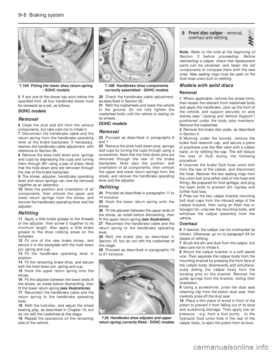
16Fit the adjuster between the lower ends of
the shoes, as noted before dismantling, then
fit the lower return spring (see illustrations).
17Reconnect the handbrake cable and the
return spring to the handbrake operating
lever.
18Refit the hub/disc, and adjust the wheel
bearing play, as described in Chapter 10, but
do not refit the roadwheel at this stage.
19Repeat the operations on the remaining
side of the vehicle.20Check the handbrake cable adjustment,
as described in Section 26.
21Refit the roadwheels and lower the vehicle
to the ground. Do not fully tighten the
roadwheel bolts until the vehicle is resting on
its wheels.
DOHC models
Removal
22Proceed as described in paragraphs 6
and 7.
23Remove the shoe hold-down pins, springs
and cups by turning the cups through using a
screwdriver. Note that the hold-down pins are
removed through the rear of the brake
backplate. Note also the position and
orientation of all components, then unhook
the upper and lower return springs from the
shoes, and recover the handbrake operating
lever and the adjuster.
Refitting
24Proceed as described in paragraphs 11 to
14 inclusive.
25Hook the lower return spring onto the
shoes.
26Fit the adjuster between the upper ends of
the shoes, as noted before dismantling, then
fit the upper return spring (see illustration).
27Reconnect the handbrake cable and the
return spring to the handbrake operating
lever.
28Refit the brake disc as described in
Section 10, but do not refit the roadwheel at
this stage.
29Proceed as described in paragraphs 19
to 21 inclusive.
8Front disc caliper - removal,
overhaul and refitting
3
Note: Refer to the note at the beginning of
Section 3 before proceeding. Before
dismantling a caliper, check that replacement
parts can be obtained, and retain the old
components to compare them with the new
ones. New sealing rings must be used on the
fluid hose union bolt on refitting
Models with solid discs
Removal
1Where applicable, remove the wheel trims,
then loosen the relevant front roadwheel bolts
and apply the handbrake. Jack up the front of
the vehicle, and support securely on axle
stands (see “Jacking and Vehicle Support”)
positioned under the body side members.
Remove the roadwheel.
2Remove the brake disc pads, as described
in Section 4.
3Working under the bonnet, remove the
brake fluid reservoir cap, and secure a piece
of polythene over the filler neck with a rubber
band, or by refitting the cap. This will reduce
the loss of fluid during the following
procedure.
4Unscrew the brake fluid hose union bolt
from the rear of the caliper, and disconnect
the hose. Recover the two sealing rings from
the union bolt (one either side of the hose end
fitting). Be prepared for fluid spillage, and plug
the open ends to prevent dirt ingress and
further fluid loss.
5Prise out the two caliper bracket mounting
bolt dust caps from the inboard edge of the
caliper bracket, then using an Allen key or
hexagon bit, unscrew the mounting bolts, and
withdraw the caliper assembly from the
vehicle.
Overhaul
6If desired, the caliper can be overhauled as
follows. Otherwise, go on to paragraph 24 for
details of refitting.
7Brush the dirt and dust from the caliper, but
take care not to inhale it.
8Mount the caliper bracket in a soft-jawed
vice. Then separate the caliper body from the
mounting bracket by pressing the front face of
the caliper body downwards and simultane-
ously sliding the caliper body from the
locating pins on the bracket. Recover the
guide springs from the bracket, noting their
orientation.
9Using a screwdriver, prise the dust seal
retaining clip from the piston dust seal, then
carefully prise off the dust seal.
10Place a thin piece of wood in front of the
piston to prevent it from falling out of its bore
and sustaining damage. Then apply low air
pressure - e.g. from a foot pump - to the
hydraulic fluid union hole in the rear of the
caliper body, to eject the piston from its bore.
9•8Braking system
7.16A Fitting the lower shoe return spring
- SOHC models
7.26 Handbrake shoe adjuster and upper
return spring correctly fitted - DOHC models
7.16B Handbrake shoe components
correctly assembled - SOHC models