1988 OPEL VECTRA bonnet
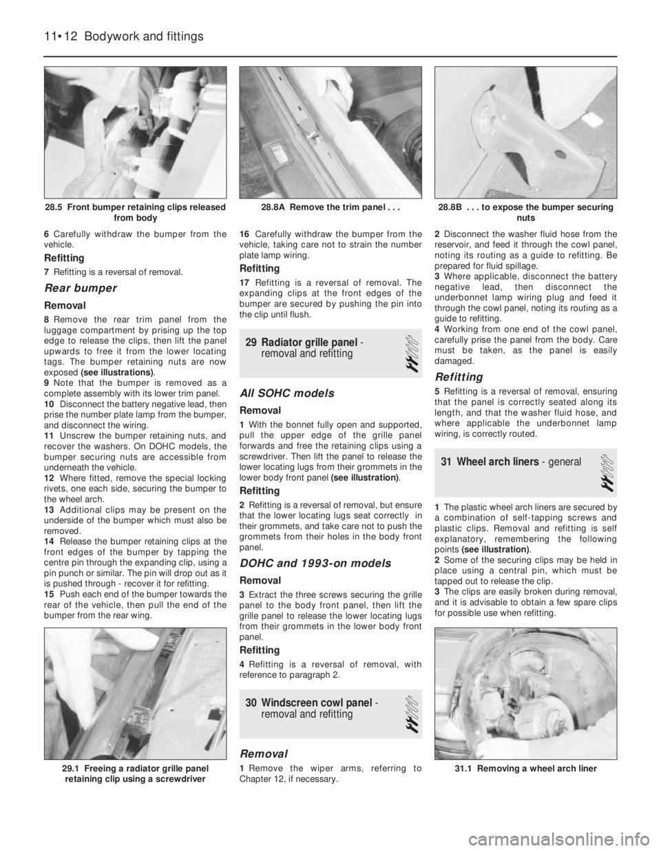
[x] Cancel search: bonnetPage 23 of 525
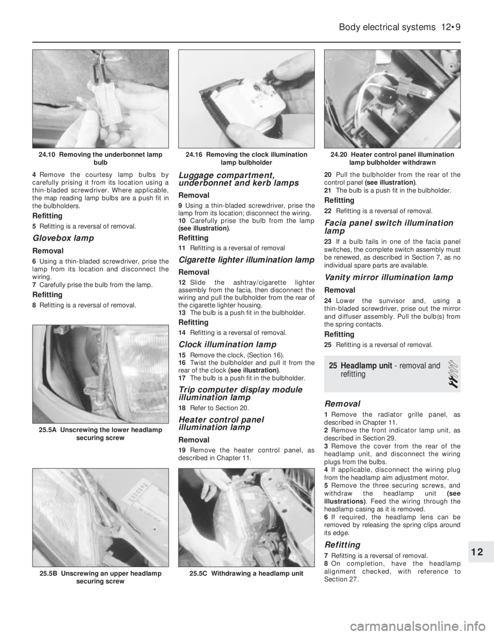
4Remove the courtesy lamp bulbs by
carefully prising it from its location using a
thin-bladed screwdriver. Where applicable,
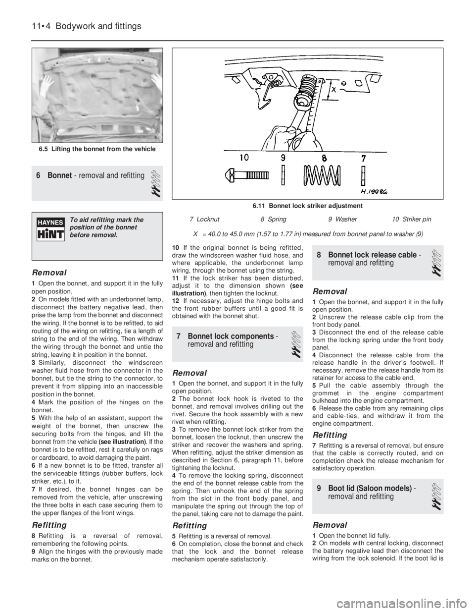
the map reading lamp bulbs are a push fit in
the bulbholders.
Refitting
5Refitting is a reversal of removal.
Glovebox lamp
Removal
6Using a thin-bladed screwdriver, prise the
lamp from its location and disconnect the
wiring.
7Carefully prise the bulb from the lamp.
Refitting
8Refitting is a reversal of removal.
Luggage compartment,
underbonnet and kerb lamps
Removal
9Using a thin-bladed screwdriver, prise the
lamp from its location; disconnect the wiring.
10Carefully prise the bulb from the lamp
(see illustration).
Refitting
11Refitting is a reversal of removal
Cigarette lighter illumination lamp
Removal
12Slide the ashtray/cigarette lighter
assembly from the facia, then disconnect the
wiring and pull the bulbholder from the rear of
the cigarette lighter housing.
13The bulb is a push fit in the bulbholder.
Refitting
14Refitting is a reversal of removal.
Clock illumination lamp
15Remove the clock, (Section 16).
16Twist the bulbholder and pull it from the
rear of the clock (see illustration).
17The bulb is a push fit in the bulbholder.
Trip computer display module
illumination lamp
18Refer to Section 20.
Heater control panel
illumination lamp
Removal
19Remove the heater control panel, as
described in Chapter 11. 20Pull the bulbholder from the rear of the
control panel (see illustration).
21The bulb is a push fit in the bulbholder.
Refitting
22Refitting is a reversal of removal.
Facia panel switch illumination
lamp
23If a bulb fails in one of the facia panel
switches, the complete switch assembly must
be renewed, as described in Section 7, as no
individual spare parts are available.
Vanity mirror illumination lamp
Removal
24Lower the sunvisor and, using a
thin-bladed screwdriver, prise out the mirror
and diffuser assembly. Pull the bulb(s) from
the spring contacts.
Refitting
25Refitting is a reversal of removal.
25Headlamp unit - removal and
refitting
2
Removal
1Remove the radiator grille panel, as
described in Chapter 11.
2Remove the front indicator lamp unit, as
described in Section 29.
3Remove the cover from the rear of the
headlamp unit, and disconnect the wiring
plugs from the bulbs.
4If applicable, disconnect the wiring plug
from the headlamp aim adjustment motor.
5Remove the three securing screws, and
withdraw the headlamp unit (see
illustrations). Feed the wiring through the
headlamp casing as it is removed.
6If required, the headlamp lens can be
removed by releasing the spring clips around
its edge.
Refitting
7Refitting is a reversal of removal.
8On completion, have the headlamp
alignment checked, with reference to
Section 27.
Body electrical systems 12•9
24.20 Heater control panel illumination
lamp bulbholder withdrawn
25.5C Withdrawing a headlamp unit25.5B Unscrewing an upper headlamp
securing screw
25.5A Unscrewing the lower headlamp
securing screw
24.16 Removing the clock illumination
lamp bulbholder24.10 Removing the underbonnet lamp
bulb
12
Page 27 of 525
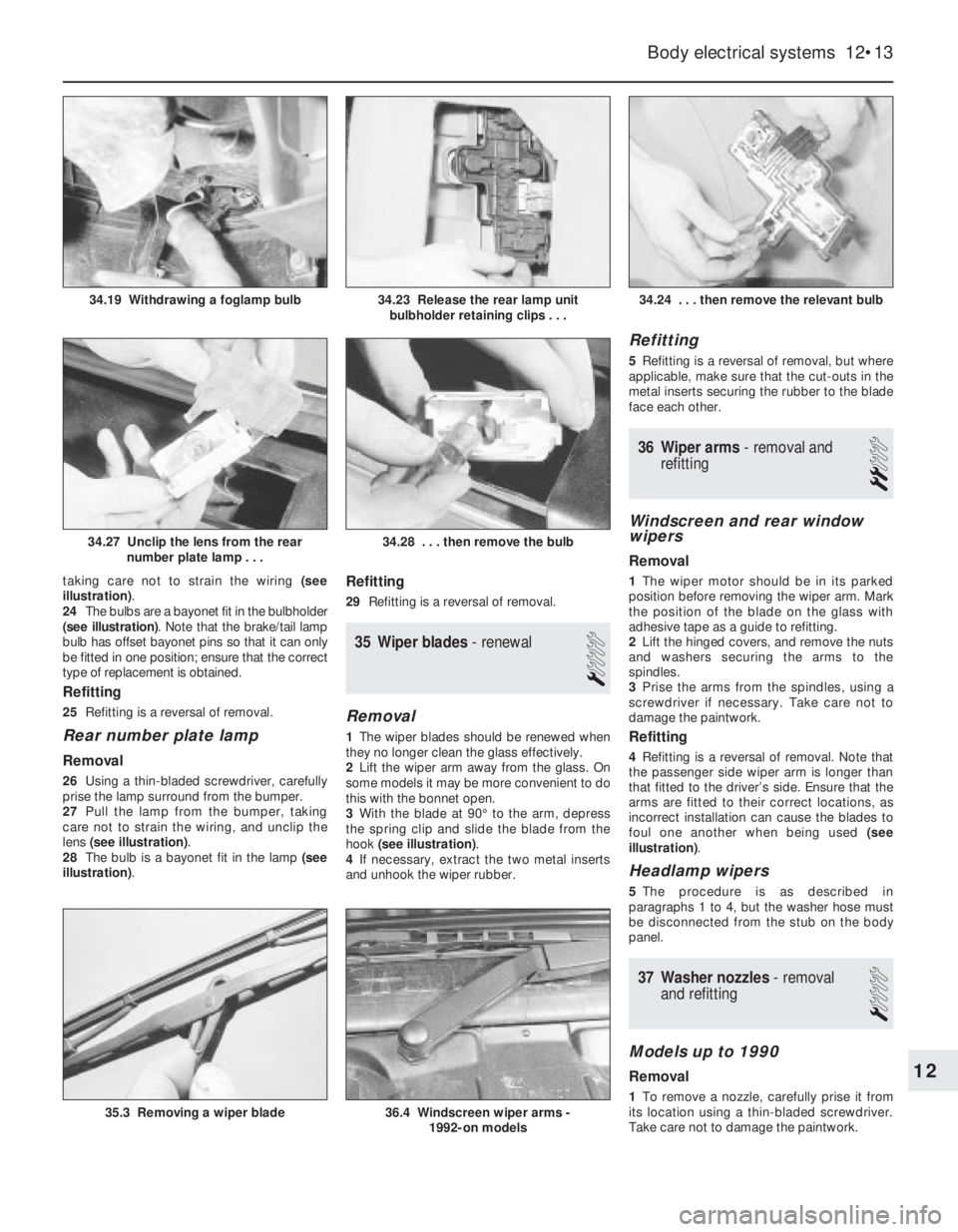
taking care not to strain the wiring (see
illustration).
24The bulbs are a bayonet fit in the bulbholder
(see illustration). Note that the brake/tail lamp
bulb has offset bayonet pins so that it can only
be fitted in one position; ensure that the correct
type of replacement is obtained.
Refitting
25Refitting is a reversal of removal.
Rear number plate lamp
Removal
26Using a thin-bladed screwdriver, carefully
prise the lamp surround from the bumper.
27Pull the lamp from the bumper, taking
care not to strain the wiring, and unclip the
lens (see illustration).
28The bulb is a bayonet fit in the lamp (see
illustration).
Refitting
29Refitting is a reversal of removal.
35Wiper blades -renewal
1
Removal
1The wiper blades should be renewed when
they no longer clean the glass effectively.
2Lift the wiper arm away from the glass. On
some models it may be more convenient to do
this with the bonnet open.
3With the blade at 90°to the arm, depress
the spring clip and slide the blade from the
hook (see illustration).
4If necessary, extract the two metal inserts
and unhook the wiper rubber.
Refitting
5Refitting is a reversal of removal, but where
applicable, make sure that the cut-outs in the
metal inserts securing the rubber to the blade
face each other.
36Wiper arms - removal and
refitting
2
Windscreen and rear window
wipers
Removal
1The wiper motor should be in its parked
position before removing the wiper arm. Mark
the position of the blade on the glass with
adhesive tape as a guide to refitting.
2Lift the hinged covers, and remove the nuts
and washers securing the arms to the
spindles.
3Prise the arms from the spindles, using a
screwdriver if necessary. Take care not to
damage the paintwork.
Refitting
4Refitting is a reversal of removal. Note that
the passenger side wiper arm is longer than
that fitted to the driver’s side. Ensure that the
arms are fitted to their correct locations, as
incorrect installation can cause the blades to
foul one another when being used (see
illustration).
Headlamp wipers
5The procedure is as described in
paragraphs 1 to 4, but the washer hose must
be disconnected from the stub on the body
panel.
37Washer nozzles - removal
and refitting
1
Models up to 1990
Removal
1To remove a nozzle, carefully prise it from
its location using a thin-bladed screwdriver.
Take care not to damage the paintwork.
Body electrical systems 12•13
34.24 . . . then remove the relevant bulb
36.4 Windscreen wiper arms -
1992-on models35.3 Removing a wiper blade
34.28 . . . then remove the bulb34.27 Unclip the lens from the rear
number plate lamp . . .
34.23 Release the rear lamp unit
bulbholder retaining clips . . .34.19 Withdrawing a foglamp bulb
12
Page 33 of 525
53Anti-theft alarm - general
1Certain models are fitted with an anti-theft
alarm as standard equipment.
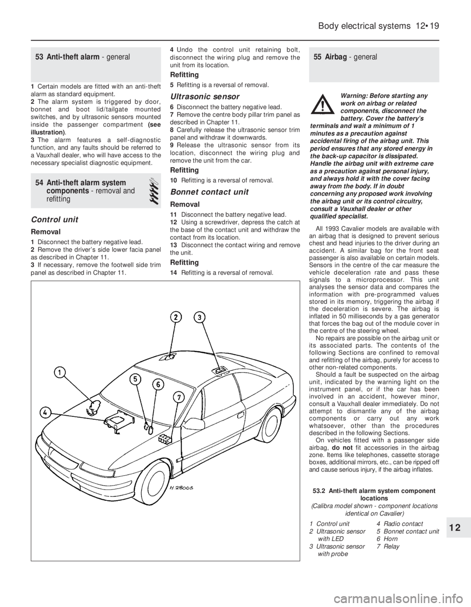
2The alarm system is triggered by door,
bonnet and boot lid/tailgate mounted
switches, and by ultrasonic sensors mounted
inside the passenger compartment (see
illustration).
3The alarm features a self-diagnostic
function, and any faults should be referred to
a Vauxhall dealer, who will have access to the
necessary specialist diagnostic equipment.
54Anti-theft alarm system
components -removal and
refitting
4
Control unit
Removal
1Disconnect the battery negative lead.
2Remove the driver’s side lower facia panel
as described in Chapter 11.
3If necessary, remove the footwell side trim
panel as described in Chapter 11.4Undo the control unit retaining bolt,
disconnect the wiring plug and remove the
unit from its location.
Refitting
5Refitting is a reversal of removal.
Ultrasonic sensor
6Disconnect the battery negative lead.
7Remove the centre body pillar trim panel as
described in Chapter 11.
8Carefully release the ultrasonic sensor trim
panel and withdraw it downwards.
9Release the ultrasonic sensor from its
location, disconnect the wiring plug and
remove the unit from the car.
Refitting
10Refitting is a reversal of removal.
Bonnet contact unit
Removal
11Disconnect the battery negative lead.
12Using a screwdriver, depress the catch at
the base of the contact unit and withdraw the
contact from its location.
13Disconnect the contact wiring and remove
the unit.
Refitting
14Refitting is a reversal of removal.
55Airbag - general
All 1993 Cavalier models are available with
an airbag that is designed to prevent serious
chest and head injuries to the driver during an
accident. A similar bag for the front seat
passenger is also available on certain models.
Sensors in the centre of the car measure the
vehicle deceleration rate and pass these
signals to a microprocessor. This unit
analyses the sensor data and compares the
information with pre-programmed values
stored in its memory, triggering the airbag if
the deceleration is severe. The airbag is
inflated in 50 milliseconds by a gas generator
that forces the bag out of the module cover in
the centre of the steering wheel.
No repairs are possible on the airbag unit or
its associated parts. The contents of the
following Sections are confined to removal
and refitting of the airbag, purely for access to
other non-related components.
Should a fault be suspected on the airbag
unit, indicated by the warning light on the
instrument panel, or if the car has been
involved in an accident, however minor,
consult a Vauxhall dealer immediately. Do not
attempt to dismantle any of the airbag
components or carry out any work
whatsoever, other than the procedures
described in the following Sections.
On vehicles fitted with a passenger side
airbag, do notfit accessories in the airbag
zone. Items like telephones, cassette storage
boxes, additional mirrors, etc., can be ripped off
and cause serious injury, if the airbag inflates.
Body electrical systems 12•19
12
53.2 Anti-theft alarm system component
locations
(Calibra model shown - component locations
identical on Cavalier)
1 Control unit
2 Ultrasonic sensor
with LED
3 Ultrasonic sensor
with probe4 Radio contact
5 Bonnet contact unit
6 Horn
7 Relay
Warning: Before starting any
work on airbag or related
components, disconnect the
battery. Cover the battery’s
terminals and wait a minimum of 1
minutes as a precaution against
accidental firing of the airbag unit. This
period ensures that any stored energy in
the back-up capacitor is dissipated.
Handle the airbag unit with extreme care
as a precaution against personal injury,
and always hold it with the cover facing
away from the body. If in doubt
concerning any proposed work involving
the airbag unit or its control circuitry,
consult a Vauxhall dealer or other
qualified specialist.
Page 54 of 525
12•40Wiring diagrams
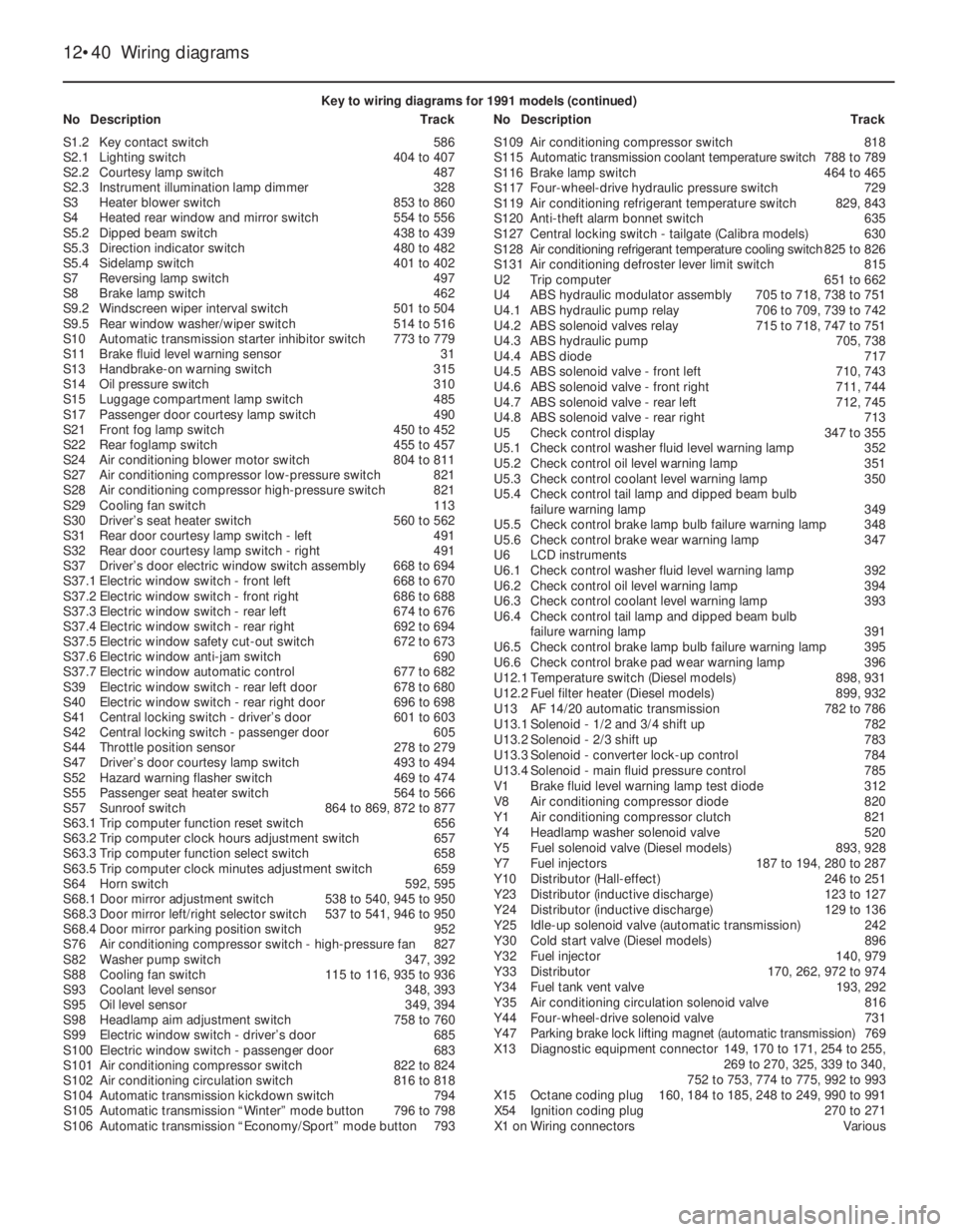
Key to wiring diagrams for 1991 models (continued)
NoDescriptionTrackNoDescriptionTrack
S1.2Key contact switch586
S2.1Lighting switch404 to 407
S2.2Courtesy lamp switch487
S2.3Instrument illumination lamp dimmer328
S3Heater blower switch853 to 860
S4Heated rear window and mirror switch554 to 556
S5.2Dipped beam switch438 to 439
S5.3Direction indicator switch480 to 482
S5.4Sidelamp switch401 to 402
S7Reversing lamp switch497
S8Brake lamp switch462
S9.2Windscreen wiper interval switch501 to 504
S9.5Rear window washer/wiper switch514 to 516
S10Automatic transmission starter inhibitor switch773 to 779
S11Brake fluid level warning sensor31
S13Handbrake-on warning switch315
S14Oil pressure switch310
S15Luggage compartment lamp switch485
S17Passenger door courtesy lamp switch490
S21Front fog lamp switch450 to 452
S22Rear foglamp switch455 to 457
S24Air conditioning blower motor switch804 to 811
S27Air conditioning compressor low-pressure switch821
S28Air conditioning compressor high-pressure switch821
S29Cooling fan switch113
S30Driver’s seat heater switch560 to 562
S31Rear door courtesy lamp switch - left491
S32Rear door courtesy lamp switch - right491
S37Driver’s door electric window switch assembly668 to 694
S37.1Electric window switch - front left668 to 670
S37.2Electric window switch - front right686 to 688
S37.3Electric window switch - rear left674 to 676
S37.4Electric window switch - rear right692 to 694
S37.5Electric window safety cut-out switch672 to 673
S37.6Electric window anti-jam switch690
S37.7Electric window automatic control677 to 682
S39Electric window switch - rear left door678 to 680
S40Electric window switch - rear right door696 to 698
S41Central locking switch - driver’s door601 to 603
S42Central locking switch - passenger door605
S44Throttle position sensor278 to 279
S47Driver’s door courtesy lamp switch493 to 494
S52Hazard warning flasher switch469 to 474
S55Passenger seat heater switch564 to 566
S57Sunroof switch864 to 869, 872 to 877
S63.1Trip computer function reset switch656
S63.2Trip computer clock hours adjustment switch657
S63.3Trip computer function select switch658
S63.5Trip computer clock minutes adjustment switch659
S64Horn switch592, 595
S68.1Door mirror adjustment switch538 to 540, 945 to 950
S68.3Door mirror left/right selector switch537 to 541, 946 to 950
S68.4Door mirror parking position switch952
S76Air conditioning compressor switch - high-pressure fan827
S82Washer pump switch347, 392
S88Cooling fan switch115 to 116, 935 to 936
S93Coolant level sensor348, 393
S95Oil level sensor349, 394
S98Headlamp aim adjustment switch758 to 760
S99Electric window switch - driver’s door685
S100Electric window switch - passenger door683
S101Air conditioning compressor switch822 to 824
S102Air conditioning circulation switch816 to 818
S104Automatic transmission kickdown switch794
S105Automatic transmission “Winter” mode button796 to 798
S106Automatic transmission “Economy/Sport” mode button793S109Air conditioning compressor switch818
S115Automatic transmission coolant temperature switch788 to 789
S116Brake lamp switch464 to 465
S117Four-wheel-drive hydraulic pressure switch729
S119Air conditioning refrigerant temperature switch829, 843
S120Anti-theft alarm bonnet switch635
S127Central locking switch - tailgate (Calibra models)630
S128Air conditioning refrigerant temperature cooling switch825 to 826
S131Air conditioning defroster lever limit switch815
U2Trip computer651 to 662
U4ABS hydraulic modulator assembly705 to 718, 738 to 751
U4.1ABS hydraulic pump relay706 to 709, 739 to 742
U4.2ABS solenoid valves relay715 to 718, 747 to 751
U4.3ABS hydraulic pump705, 738
U4.4ABS diode717
U4.5ABS solenoid valve - front left710, 743
U4.6ABS solenoid valve - front right711, 744
U4.7ABS solenoid valve - rear left712, 745
U4.8ABS solenoid valve - rear right713
U5Check control display347 to 355
U5.1Check control washer fluid level warning lamp352
U5.2Check control oil level warning lamp351
U5.3Check control coolant level warning lamp350
U5.4Check control tail lamp and dipped beam bulb
failure warning lamp349
U5.5Check control brake lamp bulb failure warning lamp348
U5.6Check control brake wear warning lamp347
U6LCD instruments
U6.1Check control washer fluid level warning lamp392
U6.2Check control oil level warning lamp394
U6.3Check control coolant level warning lamp393
U6.4Check control tail lamp and dipped beam bulb
failure warning lamp391
U6.5Check control brake lamp bulb failure warning lamp395
U6.6Check control brake pad wear warning lamp396
U12.1Temperature switch (Diesel models)898, 931
U12.2Fuel filter heater (Diesel models)899, 932
U13AF14/20automatic transmission782 to 786
U13.1Solenoid - 1/2 and 3/4 shift up782
U13.2Solenoid - 2/3 shift up783
U13.3Solenoid - converter lock-up control784
U13.4Solenoid - main fluid pressure control785
V1Brake fluid level warning lamp test diode312
V8Air conditioning compressor diode820
Y1Air conditioning compressor clutch821
Y4Headlamp washer solenoid valve520
Y5Fuel solenoid valve (Diesel models)893, 928
Y7Fuel injectors187 to 194, 280 to 287
Y10Distributor (Hall-effect)246 to 251
Y23Distributor (inductive discharge)123 to 127
Y24Distributor (inductive discharge)129 to 136
Y25Idle-up solenoid valve (automatic transmission)242
Y30Cold start valve (Diesel models)896
Y32Fuel injector140, 979
Y33Distributor170, 262, 972 to 974
Y34Fuel tank vent valve193, 292
Y35Air conditioning circulation solenoid valve816
Y44Four-wheel-drive solenoid valve731
Y47Parking brake lock lifting magnet (automatic transmission)769
X13Diagnostic equipment connector149, 170 to 171, 254 to 255,
269 to 270, 325, 339 to 340,
752 to 753, 774 to 775, 992 to 993
X15Octane coding plug160, 184 to 185, 248 to 249, 990 to 991
X54Ignition coding plug270 to 271
X1 onWiring connectorsVarious
Page 91 of 525
28The system also incorporates a separate
ignition amplifier module that transmits
amplified signals from the main system
module to trigger the HT pulse from the
ignition coil. The module is mounted on the
ignition coil’s bracket/baseplate.
29Additionally, the Motronic module
receives information from a cylinder
block-mounted knock sensor, which senses
“knocking” (or pre-ignition) just as it begins to
occur, enabling the module to retard the
ignition timing, thus preventing engine
damage.
Simtec 56.1
30This system uses increased amount of
electronic components instead of mechanical
parts as sensors and actuators with the
Simtec engine management system. This
provides more precise operating data as well
as greater problem free motoring.
31The control unit is equipped with
electronic ignition control. Called ‘Micropro-
cessor Spark Timing System, inductive
triggered’, (or MSTS-i), and means that the
mechanical high voltage distributor is no
longer needed. It is located behind the trim
panel, on the right-hand side footwell (door
pillar).
32The ignition coil is replaced by a dual
spark ignition coil, which is switched directly
by the output stages in the control unit.
33A camshaft sensor will maintain
emergency operation, should the crankshaft
inductive pulse pick-up, malfunction. These
sense TDC (‘Top Dead Centre’), crankshaft
angle and engine speed. The signals are used
by the control unit to calculate ignition point
and for fuel injection.
34The ‘hot film airflow meter’ determines the
mass of air taken in by the engine. The system
uses this information to calculate the correct
amount of fuel needed for injection in the
engine.
35The air inlet temperature sensor (NTC), is
fitted in the air inlet duct between the air
cleaner and the hot mass air flow meter.
36A controlled canister purge valve is
actuated by the system. The tank ventilation is
monitored closely with the Lambda control (or
oxygen sensor) and adaptation by the
computer within the control unit.
37A knock control system is also fitted. This
eliminates the need for octane number
adjustment, as it is performed automatically
through the control unit.
3Electrical system -
precautions
1It is necessary to take extra care when
working on the electrical system, to avoid
damage to semi-conductor devices (diodes
and transistors), and to avoid the risk of
personal injury. Along with the precautions
given in the “Safety first!” Section at the
beginning of this manual, take note of the
following points when working on the system.
2Always remove rings, watches, etc. before
working on the electrical system. Even with
the battery disconnected, discharge could
occur if a component live terminal is earthed
through a metal object. This could cause a
shock or nasty burn.
3Do not reverse the battery connections.
Components such as the alternator, or any
other component having semi-conductor
circuitry, could be irreparably damaged.
4If the engine is being started using jump
leads and a slave battery, connect the
batteries positive to positive and negative to
negative. This also applies when connecting a
battery charger.
5Never disconnect the battery terminals, or
alternator multi-plug connector, when the
engine is running.
6The battery leads and alternator wiring
must be disconnected before carrying out any
electric welding on the vehicle.
7Never use an ohmmeter of the type
incorporating a hand-cranked generator for
circuit or continuity testing.
8Engine management modules are very
sensitive components, and certain
precautions must be taken, to avoid damage
to the module when working on a vehicle
equipped with an engine management
system, as follows.
9When carrying out welding operations on
the vehicle using electric welding equipment,
the battery and alternator should be
disconnected.
10Although underbonnet-mounted modules
will tolerate normal underbonnet conditions,
they can be adversely affected by excess heat
or moisture. If using welding equipment or
pressure washing equipment near the
module, take care not to direct heat, or jets of
water or steam, at the module. If this cannot
be avoided, remove the module from the
vehicle, and protect its wiring plug with a
plastic bag.
11Before disconnecting any wiring, or
removing components, always ensure that the
ignition is switched off.
12Do not attempt to improvise fault
diagnosis procedures using a test lamp or
multimeter, as irreparable damage could be
caused to the module.13After working on ignition/engine
management system components, ensure
that all wiring is correctly reconnected before
reconnecting the battery or switching on the
ignition.
14Any ignition system that uses a
“Hall-effect” generator in the distributor,
cannot be tested. Test equipment that uses
its own power source (e.g. an ohmmeter),
when connected to the distributor or the
“Hall-effect” generator, will be damaged.
4Ignition system testing -
general
3
Note: Refer to Section 3 before proceeding.
Always switch off the ignition before
disconnecting or connecting any component
and when using a multi-meter to check
resistances. Any voltmeter or multi-meter
used to test ignition system components must
have an impedance of 10 meg ohms or
greater
1Electronic ignition system components are
normally very reliable. Most faults are far more
likely to be due to loose or dirty connections,
or to “tracking” of HT voltage due to dirt,
dampness or damaged insulation than to
component failure. Always check all wiring
thoroughly before condemning an electrical
component and work methodically to
eliminate all other possibilities before deciding
that a particular component is faulty.
2The old practice of checking for a spark by
holding the live end of a HT lead a short
distance away from the engine is not
recommended. Not only is there a high risk of
a powerful electric shock, but the ignition coil
or amplifier module will be damaged.
Similarly, never try to “diagnose” misfires by
pulling off one HT lead at a time. Note also
that the ECU is at risk if the system is
triggered with an open (i.e., not properly
earthed) HT circuit; ECU’s are very expensive
to replace, so take care!
3If you are in any doubt as to your skill and
ability to test an ignition system component or
if you do not have the required equipment,
take the vehicle to a suitably equipped
Vauxhall dealer. It is better to pay the labour
charges involved in having the vehicle
checked by an expert than to risk damage to
the system or to yourself.
4If the engine either will not turn over at all,
or only turns very slowly, check the battery
and starter motor. Connect a voltmeter across
the battery terminals (meter positive probe to
battery positive terminal) and disconnect the
ignition coil HT lead from the distributor cap
and earth. Note the voltage reading obtained
while turning over the engine on the starter for
(no more than) ten seconds. If the reading
obtained is less than approximately 9.5 volts,
check the battery, battery connections, starter
motor and charging system.
5•4Engine electrical systems
Warning: The HT voltage
generated by an electronic
ignition system is extremely
high and, in certain
circumstances, could prove fatal. Take
care to avoid receiving electric shocks
from the HT side of the ignition system.
Do not handle HT leads, or touch the
distributor or coil, when the engine is
running. If tracing faults in the HT circuit,
use well-insulated tools to manipulate live
leads
Page 104 of 525
11
Torque wrench settingNm lbf ft
Front seat rails to floor . . . . . . . . . . . . . . . . . . . . . . . . . . . . . . . . . . . . . . 20 15
Seat belt fixings . . . . . . . . . . . . . . . . . . . . . . . . . . . . . . . . . . . . . . . . . . . 35 26
1 General description
The bodyshell and floorpan are of pressed
steel, and form an integral part of the vehicle’s
structure, without the need for a separate
chassis.
Various areas are strengthened, to provide
for suspension, steering and engine mounting
points, and load distribution.
Extensive corrosion protection is applied to
all new vehicles. Various anti-corrosion
preparations are used, including galvanising
and PVC under-sealing. Protective wax is
injected into the box sections and other
hollow cavities.
Extensive use is made of plastic for
peripheral components, such as the radiator
grille, bumpers and wheel trims, and for much
of the interior trim.Interior fittings are to a high standard on all
models, and a wide range of optional
equipment is available throughout the range.
Except for the rear quarter windows, all
fixed glass is bonded in position, using a
special adhesive. Any work in this area should
be entrusted to a Vauxhall dealer or glass
replacement specialist.
2 Bodywork and underframe -
maintenance
1
The general condition of a vehicle’s
bodywork is the one thing that significantly
affects its value. Maintenance is easy but
needs to be regular. Neglect, particularly after
minor damage, can lead quickly to further
deterioration and costly repair bills. It is
important also to keep watch on those partsof the vehicle not immediately visible, for
instance the underside, inside all the wheel
arches and the lower part of the engine
compartment.
The basic maintenance routine for the
bodywork is washing preferably with a lot of
water, from a hose. This will remove all the
loose solids that may have stuck to the
vehicle. It is important to flush these off in
such a way as to prevent grit from scratching
the finish. The wheel arches and underframe
need washing in the same way to remove any
accumulated mud that will retain moisture and
tend to encourage rust. Oddly enough, the
best time to clean the underframe and wheel
arches is in wet weather when the mud is
thoroughly wet and soft. In very wet weather
the underframe is usually cleaned of large
accumulations automatically and this is a
good time for inspection.
Periodically, except on vehicles with a
Chapter 11
Bodywork and fittings
Bodywork and underframe - maintenance . . . . . . . . . . . . . . . . . . . . . .2
Bonnet - removal and refitting . . . . . . . . . . . . . . . . . . . . . . . . . . . . . . .6
Bonnet lock components - removal and refitting . . . . . . . . . . . . . . . . .7
Bonnet lock release cable - removal and refitting . . . . . . . . . . . . . . . .8
Boot lid (Saloon models) - removal and refitting . . . . . . . . . . . . . . . . .9
Boot lid lock (Saloon models) - removal and refitting . . . . . . . . . . . . .10
Boot lid lock cylinder (Saloon models) - removal and refitting . . . . . .11
Bumpers - removal and refitting . . . . . . . . . . . . . . . . . . . . . . . . . . . . .28
Centre console - removal and refitting . . . . . . . . . . . . . . . . . . . . . . . .38
Door - removal and refitting . . . . . . . . . . . . . . . . . . . . . . . . . . . . . . . .16
Door check arm - removal and refitting . . . . . . . . . . . . . . . . . . . . . . .22
Door exterior handle - removal and refitting . . . . . . . . . . . . . . . . . . . .19
Door inner trim panel - removal and refitting . . . . . . . . . . . . . . . . . . .17
Door interior handle - removal and refitting . . . . . . . . . . . . . . . . . . . .18
Door lock - removal and refitting . . . . . . . . . . . . . . . . . . . . . . . . . . . .21
Door lock barrel - removal and refitting . . . . . . . . . . . . . . . . . . . . . . .20
Door mirror - removal, overhaul and refitting . . . . . . . . . . . . . . . . . . .27
Door window - removal and refitting . . . . . . . . . . . . . . . . . . . . . . . . .25
Door window regulator - removal and refitting . . . . . . . . . . . . . . . . . .26
Engine undershield (DOHC models) - removal and refitting . . . . . . . .32
Facia panels - removal and refitting . . . . . . . . . . . . . . . . . . . . . . . . . .37
Fuel filler flap - removal and refitting . . . . . . . . . . . . . . . . . . . . . . . . .33General description . . . . . . . . . . . . . . . . . . . . . . . . . . . . . . . . . . . . . . .1
Headlining - removal and refitting . . . . . . . . . . . . . . . . . . . . . . . . . . .39
Interior trim panels - general . . . . . . . . . . . . . . . . . . . . . . . . . . . . . . . .35
Interior trim panels - removal and refitting . . . . . . . . . . . . . . . . . . . . .36
Major body damage - repair . . . . . . . . . . . . . . . . . . . . . . . . . . . . . . . . .5
Minor body damage - repair . . . . . . . . . . . . . . . . . . . . . . . . . . . . . . . . .4
Radiator grille panel - removal and refitting . . . . . . . . . . . . . . . . . . . .29
Rear quarter windows - removal and refitting . . . . . . . . . . . . . . . . . .24
Seat belts - removal and refitting . . . . . . . . . . . . . . . . . . . . . . . . . . . .41
Seat belt tensioners - general . . . . . . . . . . . . . . . . . . . . . . . . . . . . . . .42
Seats (without tensioners) - removal and refitting . . . . . . . . . . . . . . .40
Seats, front (with seat belt tensioners) - removal and refitting . . . . . .43
Sunroof - removal and refitting . . . . . . . . . . . . . . . . . . . . . . . . . . . . . .34
Tailgate (Hatchback models) - removal and refitting . . . . . . . . . . . . .12
Tailgate lock (Hatchback models) - removal and refitting . . . . . . . . .13
Tailgate lock cylinder (Hatchback models) - removal and refitting . .14
Tailgate strut (Hatchback models) - removal and refitting . . . . . . . . .15
Upholstery and carpets - maintenance . . . . . . . . . . . . . . . . . . . . . . . .3
Wheel arch liners - general . . . . . . . . . . . . . . . . . . . . . . . . . . . . . . . . .31
Windscreen and rear window - removal and refitting . . . . . . . . . . . . .23
Windscreen cowl panel - removal and refitting . . . . . . . . . . . . . . . . .30
11•1
Specifications Contents
Easy,suitable for
novice with little
experienceFairly easy,suitable
for beginner with
some experienceFairly difficult,
suitable for competent
DIY mechanic
Difficult,suitable for
experienced DIY
mechanicVery difficult,
suitable for expert DIY
or professional
Degrees of difficulty
54321
Page 107 of 525
6Bonnet - removal and refitting
2
Removal
1Open the bonnet, and support it in the fully
open position.
2On models fitted with an underbonnet lamp,
disconnect the battery negative lead, then
prise the lamp from the bonnet and disconnect
the wiring. If the bonnet is to be refitted, to aid
routing of the wiring on refitting, tie a length of
string to the end of the wiring. Then withdraw
the wiring through the bonnet and untie the
string, leaving it in position in the bonnet.
3Similarly, disconnect the windscreen
washer fluid hose from the connector in the
bonnet, but tie the string to the connector, to
prevent it from slipping into an inaccessible
position in the bonnet.
4Mark the position of the hinges on the
bonnet.
5With the help of an assistant, support the
weight of the bonnet, then unscrew the
securing bolts from the hinges, and lift the
bonnet from the vehicle (see illustration). If the
bonnet is to be refitted, rest it carefully on rags
or cardboard, to avoid damaging the paint.
6If a new bonnet is to be fitted, transfer all
the serviceable fittings (rubber buffers, lock
striker, etc.), to it.
7If desired, the bonnet hinges can be
removed from the vehicle, after unscrewing
the three bolts in each case securing them to
the upper flanges of the front wings.
Refitting
8Refitting is a reversal of removal,
remembering the following points.
9Align the hinges with the previously made
marks on the bonnet.10If the original bonnet is being refitted,
draw the windscreen washer fluid hose, and
where applicable, the underbonnet lamp
wiring, through the bonnet using the string.
11If the lock striker has been disturbed,
adjust it to the dimension shown (see
illustration), then tighten the locknut.
12If necessary, adjust the hinge bolts and
the front rubber buffers until a good fit is
obtained with the bonnet shut.
7Bonnet lock components -
removal and refitting
2
Removal
1Open the bonnet, and support it in the fully
open position.
2The bonnet lock hook is riveted to the
bonnet, and removal involves drilling out the
rivet. Secure the hook assembly with a new
rivet when refitting.
3To remove the bonnet lock striker from the
bonnet, loosen the locknut, then unscrew the
striker and recover the washers and spring.
When refitting, adjust the striker dimension as
described in Section 6, paragraph 11, before
tightening the locknut.
4To remove the locking spring, disconnect
the end of the bonnet release cable from the
spring. Then unhook the end of the spring
from the slot in the front body panel, and
manipulate the spring out through the top of
the panel, taking care not to damage the paint.
Refitting
5Refitting is a reversal of removal.
6On completion, close the bonnet and check
that the lock and the bonnet release
mechanism operate satisfactorily.
8Bonnet lock release cable -
removal and refitting
2
Removal
1Open the bonnet, and support it in the fully
open position.
2Unscrew the release cable clip from the
front body panel.
3Disconnect the end of the release cable
from the locking spring under the front body
panel.
4Disconnect the release cable from the
release handle in the driver’s footwell. If
necessary, remove the release handle from its
retainer for access to the cable end.
5Pull the cable assembly through the
grommet in the engine compartment
bulkhead into the engine compartment.
6Release the cable from any remaining clips
and cable-ties, and withdraw it from the
engine compartment.
Refitting
7Refitting is a reversal of removal, but ensure
that the cable is correctly routed, and on
completion check the release mechanism for
satisfactory operation.
9Boot lid (Saloon models) -
removal and refitting
2
Removal
1Open the bonnet lid fully.
2On models with central locking, disconnect
the battery negative lead then disconnect the
wiring from the lock solenoid. If the boot lid is
11•4Bodywork and fittings
6.5 Lifting the bonnet from the vehicle
6.11 Bonnet lock striker adjustment
X = 40.0 to 45.0 mm (1.57 to 1.77 in) measured from bonnet panel to washer (9)
7 Locknut8 Spring9 Washer10 Striker pinTo aid refitting mark the
position of the bonnet
before removal.
Page 115 of 525
6Carefully withdraw the bumper from the
vehicle.
Refitting
7Refitting is a reversal of removal.
Rear bumper
Removal
8Remove the rear trim panel from the
luggage compartment by prising up the top
edge to release the clips, then lift the panel
upwards to free it from the lower locating
tags. The bumper retaining nuts are now
exposed (see illustrations).
9Note that the bumper is removed as a
complete assembly with its lower trim panel.
10Disconnect the battery negative lead, then
prise the number plate lamp from the bumper,
and disconnect the wiring.
11Unscrew the bumper retaining nuts, and
recover the washers. On DOHC models, the
bumper securing nuts are accessible from
underneath the vehicle.
12Where fitted, remove the special locking
rivets, one each side, securing the bumper to
the wheel arch.
13Additional clips may be present on the
underside of the bumper which must also be
removed.
14Release the bumper retaining clips at the
front edges of the bumper by tapping the
centre pin through the expanding clip, using a
pin punch or similar. The pin will drop out as it
is pushed through - recover it for refitting.
15Push each end of the bumper towards the
rear of the vehicle, then pull the end of the
bumper from the rear wing.16Carefully withdraw the bumper from the
vehicle, taking care not to strain the number
plate lamp wiring.
Refitting
17Refitting is a reversal of removal. The
expanding clips at the front edges of the
bumper are secured by pushing the pin into
the clip until flush.
29Radiator grille panel -
removal and refitting
2
All SOHC models
Removal
1With the bonnet fully open and supported,
pull the upper edge of the grille panel
forwards and free the retaining clips using a
screwdriver. Then lift the panel to release the
lower locating lugs from their grommets in the
lower body front panel (see illustration).
Refitting
2Refitting is a reversal of removal, but ensure
that the lower locating lugs seat correctly in
their grommets, and take care not to push the
grommets from their holes in the body front
panel.
DOHC and 1993-on models
Removal
3Extract the three screws securing the grille
panel to the body front panel, then lift the
grille panel to release the lower locating lugs
from their grommets in the lower body front
panel.
Refitting
4Refitting is a reversal of removal, with
reference to paragraph 2.
30Windscreen cowl panel -
removal and refitting
2
Removal
1Remove the wiper arms, referring to
Chapter 12, if necessary.2Disconnect the washer fluid hose from the
reservoir, and feed it through the cowl panel,
noting its routing as a guide to refitting. Be
prepared for fluid spillage.
3Where applicable, disconnect the battery
negative lead, then disconnect the
underbonnet lamp wiring plug and feed it
through the cowl panel, noting its routing as a
guide to refitting.
4Working from one end of the cowl panel,
carefully prise the panel from the body. Care
must be taken, as the panel is easily
damaged.
Refitting
5Refitting is a reversal of removal, ensuring
that the panel is correctly seated along its
length, and that the washer fluid hose, and
where applicable the underbonnet lamp
wiring, is correctly routed.
31Wheel arch liners - general
2
1The plastic wheel arch liners are secured by
a combination of self-tapping screws and
plastic clips. Removal and refitting is self
explanatory, remembering the following
points (see illustration).
2Some of the securing clips may be held in
place using a central pin, which must be
tapped out to release the clip.
3The clips are easily broken during removal,
and it is advisable to obtain a few spare clips
for possible use when refitting.
11•12Bodywork and fittings
28.8B . . . to expose the bumper securing
nuts
31.1 Removing a wheel arch liner29.1 Freeing a radiator grille panel
retaining clip using a screwdriver
28.8A Remove the trim panel . . .28.5 Front bumper retaining clips released
from body