1988 OPEL VECTRA trunk
[x] Cancel search: trunkPage 5 of 525
10Throttle pedal - removal and
refitting
3
Removal
1Working inside the vehicle, remove the
lower trim panel from the driver’s footwell.
2Slide the cable retainer from the bracket on
the top of the pedal, and disconnect the cable
end from the pedal.
3Extract the circlip from the right-hand end
of the pedal pivot shaft, then slide out the
pivot shaft from the left-hand side of the pivot
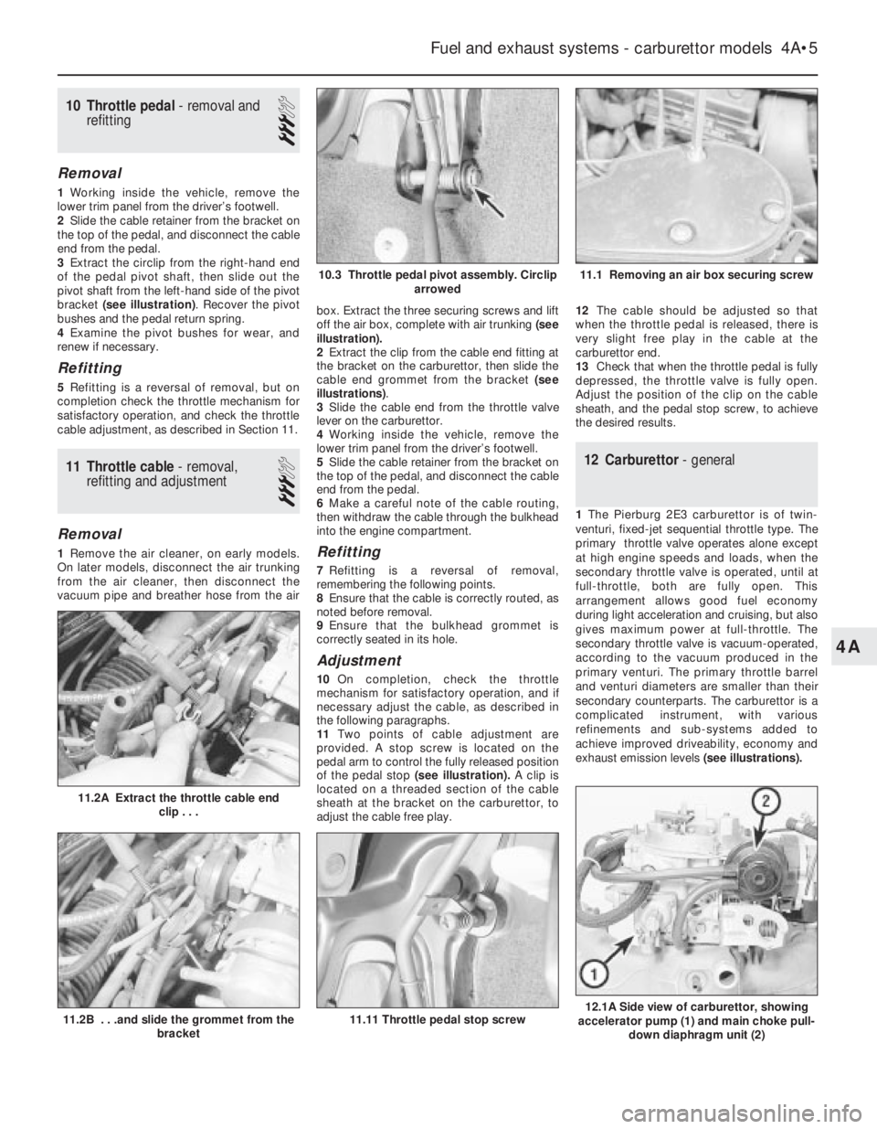
bracket (see illustration). Recover the pivot
bushes and the pedal return spring.
4Examine the pivot bushes for wear, and
renew if necessary.
Refitting
5Refitting is a reversal of removal, but on
completion check the throttle mechanism for
satisfactory operation, and check the throttle
cable adjustment, as described in Section 11.
11Throttle cable - removal,
refitting and adjustment
3
Removal
1Remove the air cleaner, on early models.
On later models, disconnect the air trunking
from the air cleaner, then disconnect the
vacuum pipe and breather hose from the airbox. Extract the three securing screws and lift
off the air box, complete with air trunking(see
illustration).
2Extract the clip from the cable end fitting at
the bracket on the carburettor, then slide the
cable end grommet from the bracket (see
illustrations).
3Slide the cable end from the throttle valve
lever on the carburettor.
4Working inside the vehicle, remove the
lower trim panel from the driver’s footwell.
5Slide the cable retainer from the bracket on
the top of the pedal, and disconnect the cable
end from the pedal.
6Make a careful note of the cable routing,
then withdraw the cable through the bulkhead
into the engine compartment.Refitting
7Refitting is a reversal of removal,
remembering the following points.
8Ensure that the cable is correctly routed, as
noted before removal.
9Ensure that the bulkhead grommet is
correctly seated in its hole.
Adjustment
10On completion, check the throttle
mechanism for satisfactory operation, and if
necessary adjust the cable, as described in
the following paragraphs.
11Two points of cable adjustment are
provided. A stop screw is located on the
pedal arm to control the fully released position
of the pedal stop (see illustration).A clip is
located on a threaded section of the cable
sheath at the bracket on the carburettor, to
adjust the cable free play.12The cable should be adjusted so that
when the throttle pedal is released, there is
very slight free play in the cable at the
carburettor end.
13Check that when the throttle pedal is fully
depressed, the throttle valve is fully open.
Adjust the position of the clip on the cable
sheath, and the pedal stop screw, to achieve
the desired results.
12Carburettor - general
1The Pierburg 2E3 carburettor is of twin-
venturi, fixed-jet sequential throttle type. The
primary throttle valve operates alone except
at high engine speeds and loads, when the
secondary throttle valve is operated, until at
full-throttle, both are fully open. This
arrangement allows good fuel economy
during light acceleration and cruising, but also
gives maximum power at full-throttle. The
secondary throttle valve is vacuum-operated,
according to the vacuum produced in the
primary venturi. The primary throttle barrel
and venturi diameters are smaller than their
secondary counterparts. The carburettor is a
complicated instrument, with various
refinements and sub-systems added to
achieve improved driveability, economy and
exhaust emission levels(see illustrations).
Fuel and exhaust systems - carburettor models 4A•5
11.2A Extract the throttle cable end
clip . . .
12.1A Side view of carburettor, showing
accelerator pump (1) and main choke pull-
down diaphragm unit (2)11.11 Throttle pedal stop screw11.2B . . .and slide the grommet from the
bracket
11.1 Removing an air box securing screw10.3 Throttle pedal pivot assembly. Circlip
arrowed
4A
Page 6 of 525
2A separate idle system operates
independently from the main jet system,
supplying fuel by way of the mixture control
screw.
3The main jets are calibrated to suit engine
requirements at mid-range throttle openings.
To provide the necessary fuel enrichment at
full throttle, a vacuum-operated power valve is
used. The valve provides extra fuel under the
low vacuum conditions associated with wide
throttle openings.
4To provide an enriched mixture during
acceleration, an accelerator pump delivers
extra fuel to the primary main venturi. The
accelerator pump is operated mechanically by
a cam on the throttle linkage.
5A fully automatic choke is fitted, operated
by a coolant and electrically heated bi-metal
coil. When the engine is cold, the bi-metal coil
is fully wound up, holding the choke plate
(fitted to the primary barrel) closed. As the
engine warms up, the bi-metal coil is heated
and therefore unwinds, progressively opening
the choke plate. A vacuum operated pull-
down system is employed, whereby, if the
engine is under choke but is only cruising (i.e.
not under heavy load) the choke plate is
opened against the action of the bi-metal coil.
The pull-down system prevents an over-rich
mixture, which reduces fuel economy and
may cause unnecessary engine wear when
the engine is cold. A secondary pull-down
solenoid is fitted, which operates in
conjunction with the main diaphragm unit to
modify the pull-down characteristics,
improving fuel economy.
61.8 litre models are fitted with an idle cut-off
solenoid. This is an electrically operated valve,
which interrupts the idle mixture circuit when
the ignition is switched off, this preventing
engine “run-on”.13Carburettor - removal,
overhaul and refitting
3
Note: Refer to Section 2 before proceeding.
New gasket(s) must be used when refitting the
carburettor. A tachometer and an exhaust gas
analyser will be required to check the idle
speed and mixture on completion
Removal
1Disconnect the battery negative lead.
2Remove the air cleaner, on early models.
On later models, disconnect the air trunking
from the air cleaner, then disconnect the
vacuum pipe and breather hose from the air
box. Extract the three securing screws and lift
off the air box, complete with air trunking.
3On 1.4 litre models, disconnect the fuel
supply hose from the carburettor, and on 1.6
and 1.8 litre models, disconnect the fuel
supply and return hoses from the vapour
separator. Be prepared for fuel spillage, and
take adequate fire precautions. Plug the ends
of the hoses, to prevent dirt ingress and
further fuel spillage.
4Extract the clip from the throttle cable end
fitting at the bracket on the carburettor, then
slide the cable end grommet from the bracket,
and slide the cable end from the throttle valve
lever.
5Disconnect the coolant hoses from the
automatic choke housing noting their
locations, as an aid to refitting. Be prepared
for coolant spillage, and plug the hoses, or
secure them with their ends facing upwards,
to prevent further coolant loss.
6Disconnect the vacuum pipes from the front
of the carburettor, noting their locations and
routing for use when refitting (see
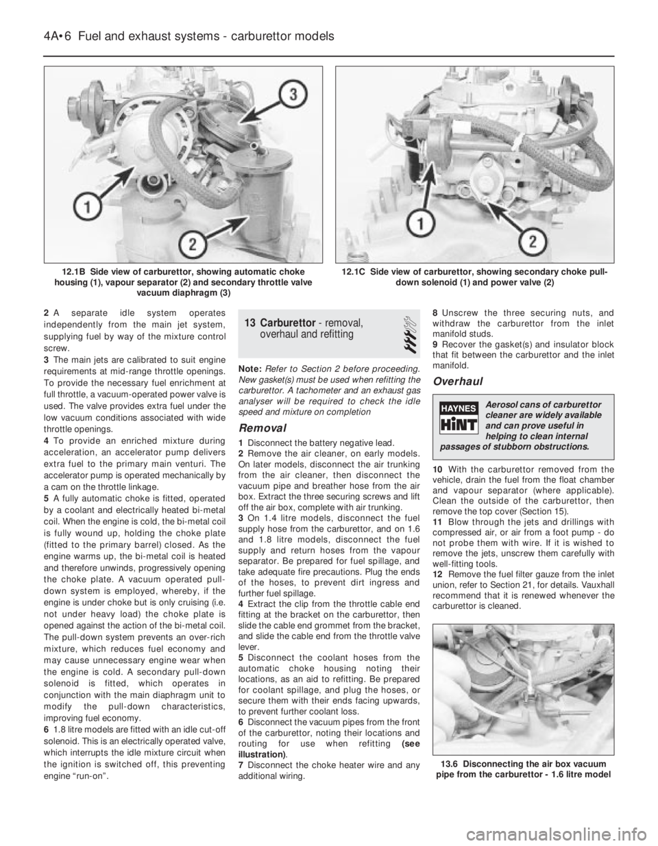
illustration).
7Disconnect the choke heater wire and any
additional wiring.8Unscrew the three securing nuts, and
withdraw the carburettor from the inlet
manifold studs.
9Recover the gasket(s) and insulator block
that fit between the carburettor and the inlet
manifold.
Overhaul
10With the carburettor removed from the
vehicle, drain the fuel from the float chamber
and vapour separator (where applicable).
Clean the outside of the carburettor, then
remove the top cover (Section 15).
11Blow through the jets and drillings with
compressed air, or air from a foot pump - do
not probe them with wire. If it is wished to
remove the jets, unscrew them carefully with
well-fitting tools.
12Remove the fuel filter gauze from the inlet
union, refer to Section 21, for details. Vauxhall
recommend that it is renewed whenever the
carburettor is cleaned.
4A•6Fuel and exhaust systems - carburettor models
12.1B Side view of carburettor, showing automatic choke
housing (1), vapour separator (2) and secondary throttle valve
vacuum diaphragm (3)12.1C Side view of carburettor, showing secondary choke pull-
down solenoid (1) and power valve (2)
13.6 Disconnecting the air box vacuum
pipe from the carburettor - 1.6 litre model
Aerosol cans of carburettor
cleaner are widely available
and can prove useful in
helping to clean internal
passages of stubborn obstructions.
Page 7 of 525
13Clean any foreign matter from the float
chamber. Renew the float, the float needle
valve and seat if wear is evident, or if the float
is punctured or otherwise damaged. Check
that the needle valve closes completely before
the float reaches the top of its movement. See
Section 15, for details of float level checking.
14Renew the diaphragms in the part-load
enrichment valve and in the accelerator pump.
If additional pump or valve parts are supplied
in the overhaul kit, renew these parts also.
15Further dismantling is not recommended.
Pay particular attention to the throttle opening
mechanism arrangement if it is decided to
dismantle it; the interlocking arrangement is
important.
16Reassemble in the reverse order to
dismantling. Use new gaskets and seals
throughout; lubricate linkages with a smear of
molybdenum based grease.
Refitting
17Carry out the following procedure before
refitting.
a)Position the fast idle adjustment screw on
the highest step of the fast idle cam.
b)Use a gauge rod or twist drill of the
specified diameter to measure the
opening of the primary throttle valve.
c)Adjust if necessary at the fast idle
adjustment screw.
d)Note that this is a preliminary adjustment;
final adjustment of the fast idle speed
should take place with the engine running.
18Refitting is a reversal of removal, but
renew the gasket(s).
19After refitting, carry out the following
checks and adjustments.
20Check the throttle cable free play and
adjust if necessary, as described in Section 11.
21Check and if necessary top-up the
coolant level, as described in Chapter 3.
22Check and if necessary adjust the idle
speed and mixture, as described in Section 14.
14Idle speed and mixture -
adjustment
3
Note: Refer to Section 2 before proceeding.
To carry out the adjustments, an accurate
tachometer and an exhaust gas analyser (CO
meter) will be required
1To check the idle speed and mixture
adjustment, the following conditions must be
met:
a)The engine must be at normal operating
temperature
b)All electrical consumers (cooling fan,
heater blower, headlamps, etc.) must be
switched off
c)The ignition timing and spark plug gaps
must be correctly adjusted - see Chapters
1 and 5
d)The throttle cable free play must be
correctly adjusted - see Section 11
e)The air inlet trunking must be free from
leaks, and the air filter must be cleanf)On automatic models, always select
position, “P”.
2Connect a tachometer and an exhaust gas
analyser to the vehicle, according to the
equipment manufacturer’s instructions.
3Start the engine, and run it at 2000 rpm for
approximately 30 seconds, then allow it to
idle. If the idle speed is outside the specified
limits, adjust by means of the throttle stop
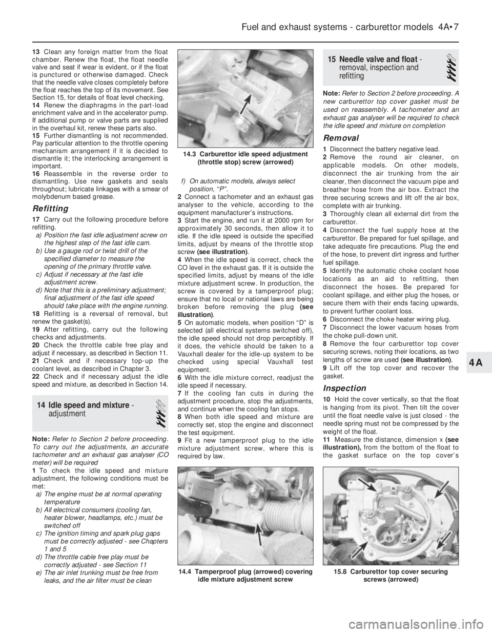
screw (see illustration).
4When the idle speed is correct, check the
CO level in the exhaust gas. If it is outside the
specified limits, adjust by means of the idle
mixture adjustment screw. In production, the
screw is covered by a tamperproof plug;
ensure that no local or national laws are being
broken before removing the plug (see
illustration).
5On automatic models, when position “D” is
selected (all electrical systems switched off),
the idle speed should not drop perceptibly. If
it does, the vehicle should be taken to a
Vauxhall dealer for the idle-up system to be
checked using special Vauxhall test
equipment.
6With the idle mixture correct, readjust the
idle speed if necessary.
7If the cooling fan cuts in during the
adjustment procedure, stop the adjustments,
and continue when the cooling fan stops.
8When both idle speed and mixture are
correctly set, stop the engine and disconnect
the test equipment.
9Fit a new tamperproof plug to the idle
mixture adjustment screw, where this is
required by law.
15Needle valve and float -
removal, inspection and
refitting
4
Note: Refer to Section 2 before proceeding. A
new carburettor top cover gasket must be
used on reassembly. A tachometer and an
exhaust gas analyser will be required to check
the idle speed and mixture on completion
Removal
1Disconnect the battery negative lead.
2Remove the round air cleaner, on
applicable models. On other models,
disconnect the air trunking from the air
cleaner, then disconnect the vacuum pipe and
breather hose from the air box. Extract the
three securing screws and lift off the air box,
complete with air trunking.
3Thoroughly clean all external dirt from the
carburettor.
4Disconnect the fuel supply hose at the
carburettor. Be prepared for fuel spillage, and
take adequate fire precautions. Plug the end
of the hose, to prevent dirt ingress and further
fuel spillage.
5Identify the automatic choke coolant hose
locations as an aid to refitting, then
disconnect the hoses. Be prepared for
coolant spillage, and either plug the hoses, or
secure them with their ends facing upwards,
to prevent further coolant loss.
6Disconnect the choke heater wiring plug.
7Disconnect the lower vacuum hoses from
the choke pull-down unit.
8Remove the four carburettor top cover
securing screws, noting their locations, as two
lengths of screw are used (see illustration).
9Lift off the top cover and recover the
gasket.
Inspection
10Hold the cover vertically, so that the float
is hanging from its pivot. Then tilt the cover
until the float needle valve is just closed - the
needle spring must not be compressed by the
weight of the float.
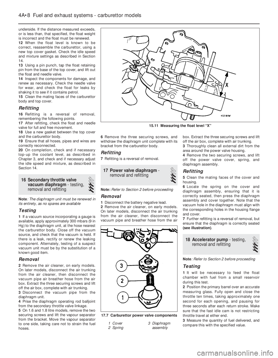
11Measure the distance, dimension x (see
illustration),from the bottom of the float to
the gasket surface on the top cover’s
Fuel and exhaust systems - carburettor models 4A•7
15.8 Carburettor top cover securing
screws (arrowed)14.4 Tamperproof plug (arrowed) covering
idle mixture adjustment screw
14.3 Carburettor idle speed adjustment
(throttle stop) screw (arrowed)
4A
Page 8 of 525
underside. If the distance measured exceeds,
or is less than, that specified, the float weight
is incorrect and the float must be renewed.
12When the float level is known to be
correct, reassemble the carburettor, using a
new top cover gasket. Check the idle speed
and mixture settings as described in Section
14.
13Using a pin punch, tap the float retaining
pin from the base of the top cover, and lift out
the float and needle valve.
14Inspect the components for damage, and
renew as necessary. Check the needle valve
for wear, and check the float for leaks by
shaking it to see if it contains petrol.
15Clean the mating faces of the carburettor
body and top cover.
Refitting
16Refitting is a reversal of removal,
remembering the following points.
17After refitting, check the float and needle
valve for full and free movement.
18Use a new gasket between the top cover
and the carburettor body.
19Ensure that all hoses, pipes and wires are
correctly reconnected.
20On completion, check and if necessary
top-up the coolant level, as described in
Chapter 3, and check and if necessary adjust
the idle speed and mixture, as described in
Section 14.
16Secondary throttle valve
vacuum diaphragm - testing,
removal and refitting
3
Note: The diaphragm unit must be renewed in
its entirety, as no spares are available
Testing
1If a vacuum source incorporating a gauge is
available, apply approximately 300 mbars (9 in
Hg) to the diaphragm unit, at the hose nearest
the carburettor body. Close off the vacuum
source, and check that the vacuum is held. If
there is a leak, rectify or renew the leaking
component. Alternately, testing of a suspect
vacuum unit must be by the substitution of a
known good item.
Removal
2Remove the air cleaner, on early models.
On later models, disconnect the air trunking
from the air cleaner, then disconnect the
vacuum pipe air breather hose from the air
box. Extract the three securing screws and lift
off the air box, complete with air trunking.
3Disconnect the vacuum pipe from the
diaphragm unit.
4Prise the diaphragm operating rod balljoint
from the secondary throttle valve linkage.
5On 1.6 and 1.8 litre models, remove the two
securing screws and lift the vapour separator
from the bracket. Move the vapour separator
to one side, taking care not to strain the fuel
hoses.6Remove the three securing screws, and
withdraw the diaphragm unit complete with its
bracket from the carburettor body.
Refitting
7Refitting is a reversal of removal.
17Power valve diaphragm -
removal and refitting
3
Note: Refer to Section 2 before proceeding
Removal
1Disconnect the battery negative lead.
2Remove the air cleaner, on early models.
On later models, disconnect the air trunking
from the air cleaner, then disconnect the
vacuum pipe and breather hose from the airbox. Extract the three securing screws and lift
off the air box, complete with air trunking.
3Thoroughly clean all external dirt from the
area around the power valve housing.
4Remove the two securing screws, and lift
off the power valve cover, spring, and
diaphragm assembly.
Refitting
5Clean the mating faces of the cover and
housing.
6Locate the spring on the cover and
diaphragm assembly, ensuring that it is
correctly seated, then press the diaphragm
assembly and cover together. Note that the
vacuum hole in the diaphragm must align with
the corresponding holes in the housing flange
and cover.
7Further refitting is a reversal of removal, but
ensure that the diaphragm is correctly seated
(see illustration).
18Accelerator pump - testing,
removal and refitting
3
Note: Refer to Section 2 before proceeding
Testing
1It will be necessary to feed the float
chamber with fuel from a small reservoir
during this test.
2Position the primary barrel over an accurate
measuring glass. Fully open and close the
throttle ten times, taking approximately one
second for each opening, and pausing for
three seconds after each return stroke. Make
sure that the fast idle cam is not restricting
throttle travel at either end.
3Measure the quantity of fuel delivered, and
compare this with the specified value.
4A•8Fuel and exhaust systems - carburettor models
15.11 Measuring the float level “X”
17.7 Carburettor power valve components
1 Cover
2 Spring3 Diaphragm
assembly
Page 93 of 525
8Alternator drivebelt -
removal, refitting and adjusting
2
V-belt type (not-ribbed)
Removal
1Disconnect the air inlet trunking from the air
cleaner, and the air box or throttle body, as
applicable, and remove it for improved
access.
2Correct tensioning of the drivebelt will
ensure that it has a long life. Beware,
however, of overtightening, as this can cause
excessive wear in the alternator.
3The belt should be inspected regularly, and
if it is found to be worn, frayed or cracked, it
should be renewed as a precaution against
breakage in service. It is advisable to carry a
spare drivebelt of the correct type in the
vehicle always.
4On models with power steering, the
alternator drivebelt also drives the power
steering pump.
5To remove the belt, on 1.8 and 2.0 litre
models first remove the power steering pump
drivebelt, as described in Chapter 10.
6Loosen the two alternator mounting nuts
and bolts sufficiently to allow the alternator to
be pivoted in towards the engine.
7Slide the belt from the pulleys.
Refitting
8Ensure that the correct type of belt is used,
if it is being renewed. Fit the belt around the
pulleys. Take up the slack in the belt byswinging the alternator away from the engine
and lightly tightening the mounting nuts and
bolts.
Adjusting
9Although special tools are available for
measuring the belt tension, a good
approximation can be achieved if the belt is
tensioned so that there is approximately 13.0
mm (0.5 in) of free movement under firm
thumb pressure at the mid-point of the
longest run between pulleys.
10With the mounting bolts just holding the
unit, lever the alternator away from the engine
using a wooden lever at the mounting bracket
end until the correct tension is achieved. Then
tighten the mounting nuts and bolts. On no
account lever at the free end of the alternator,
as serious internal damage could be caused.11Where applicable, refit and tension the
power steering pump drivebelt, as described
in Chapter 10.
12Refit the air inlet trunking.
13When a new belt has been fitted, it will
probably stretch slightly when it is first run,
and the tension should be rechecked and if
necessary adjusted after approximately 250
miles (400 km).
Ribbed V-belt type
General
14Later models equipped with power
steering are fitted with a ribbed V-belt type
drivebelt in conjunction with an automatic
tensioning roller. Once the belt is installed, no
further adjustment is necessary as the correct
tension is maintained by the automatic
tensioning roller. Removal and refitting
procedures are as follows.
Removal
15For improved access, remove the air
cleaner assembly and air inlet trunking.
16If the original drivebelt is to be refitted, mark
the rotational direction on the belt with chalk.
17Using a spanner or socket on the
automatic tensioning roller hexagon, turn the
tensioning roller clockwise (as viewed from the
right-hand side of the car) and hold it in this
position. With the drivebelt tension released,
slip the drivebelt off the pulleys, then allow the
tensioner to return to its original position.
18Support the engine under the sump with a
jack and interposed block of wood.
19From under the car, unbolt the right-hand
engine mounting block from the body.
20Lower the engine support jack just
sufficiently to allow the drivebelt to be
withdrawn from between the mounting block
and the body.
Refitting
21Slip the new drivebelt between the
mounting block and body then raise the
engine, by means of the jack, to its original
position.
22Clean the threads of the mounting block
retaining bolts, apply locking fluid, and refit
the bolts. Tighten the bolts to the specified
torque (see Chapter 2A).
23Rotate the automatic tensioner roller anti-
clockwise and route the drivebelt around the
pulleys as shown (see illustration). With the
belt correctly positioned, release the tensioner
that will automatically apply the correct
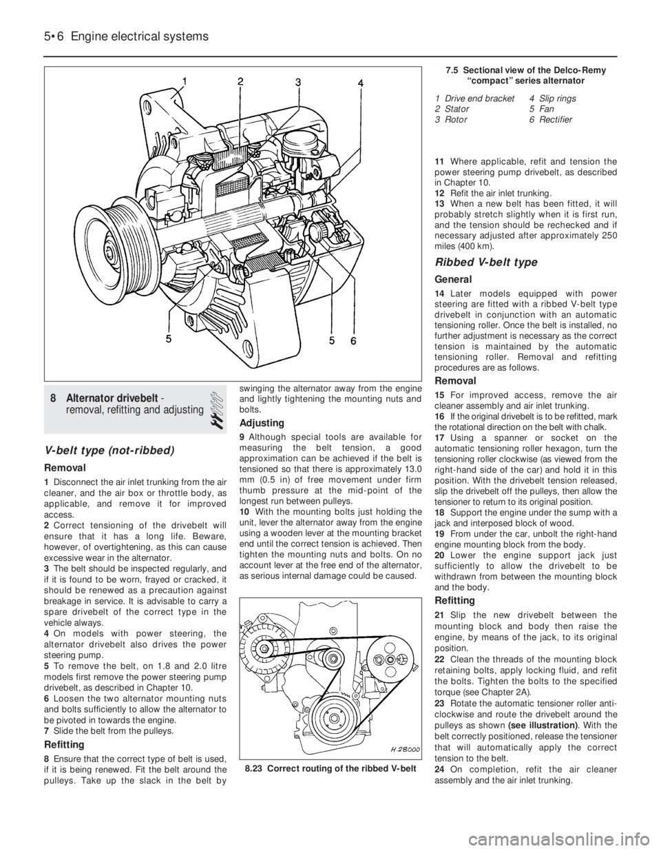
tension to the belt.
24On completion, refit the air cleaner
assembly and the air inlet trunking.
5•6Engine electrical systems
7.5 Sectional view of the Delco-Remy
“compact” series alternator
1 Drive end bracket
2 Stator
3 Rotor4 Slip rings
5 Fan
6 Rectifier
8.23 Correct routing of the ribbed V-belt
Page 94 of 525
9Alternator-removal and
refitting
3
Note: Refer to Section 3 before proceeding
Except ‘compact’ series
alternators
Removal
1Disconnect the battery leads.
2Disconnect the air trunking from the air
cleaner, and the air box or throttle body, as
applicable, and remove it for improved
access.
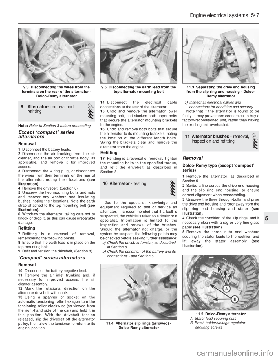
3Disconnect the wiring plug, or disconnect
the wires from their terminals on the rear of
the alternator, noting their locations (see
illustration).
4Remove the drivebelt, (Section 8).
5Unscrew the two mounting bolts and nuts
and recover any washers and insulating
bushes, noting their locations. Note the earth
strap attached to the top mounting bolt (see
illustration).
6Withdraw the alternator, taking care not to
knock or drop it, as this can cause irreparable
damage.
Refitting
7Refitting is a reversal of removal,
remembering the following points.
8Ensure that the earth lead is in place on the
top mounting bolt.
9Refit and tension the drivebelt, (Section 8).
‘Compact’ series alternators
Removal
10Disconnect the battery negative lead.
11Remove the air inlet trunking and, if
necessary for improved access, the air
cleaner assembly.
12Mark the rotational direction on the
alternator drivebelt with chalk.
13Using a spanner or socket on the
automatic tensioning roller hexagon turn the
tensioning roller clockwise (as viewed from
the right-hand side of the car) and hold it in
this position. With the drivebelt tension
released, slip the drivebelt off the alternator
pulley, then allow the tensioner to return to its
original position.14Disconnect the electrical cable
connections at the rear of the alternator.
15Undo and remove the alternator lower
mounting bolt, and slacken both upper bolts
that secure the alternator mounting brackets
to the engine.
16Undo and remove both bolts that secure
the alternator to its mounting brackets, noting
the location of the different length bolts.
Swing the brackets clear and remove the
alternator from the engine.
Refitting
17Refitting is a reversal of removal. Tighten
the mounting bolts to the specified torque,
and refit the drivebelt as described in
Section 8.
10Alternator -testing
5
Due to the specialist knowledge and
equipment required to test or service an
alternator, it is recommended that if a fault is
suspected, the vehicle is taken to a dealer or a
specialist. Information is limited to the
inspection and renewal of the brushes.
Should the alternator not charge, or the
system be suspect, the following points may
be checked before seeking further assistance:
a)Check the drivebelt tension, as described
in Section 8
b)Check the condition of the battery and its
connections -see Section 5c)Inspect all electrical cables and
connections for condition and security
Note that if the alternator is found to be
faulty, it may prove more economical to buy a
factory-reconditioned unit, rather than having
the existing unit overhauled.
11Alternator brushes -removal,
inspection and refitting
3
Removal
Delco-Remy type (except ‘compact’
series)
1Remove the alternator, as described in
Section 9
2Scribe a line across the drive end housing
and the slip ring end housing, to ensure
correct alignment when reassembling.
3Unscrew the three through-bolts, and prise
the drive end housing and rotor away from the
slip ring end housing and stator (see
illustration).
4Check the condition of the slip rings, and if
necessary clean with a rag or very fine glass
paper (see illustration).
5Remove the three nuts and washers
securing the stator leads to the rectifier, and
lift away the stator assembly (see
illustration).
Engine electrical systems 5•7
11.3 Separating the drive end housing
from the slip ring end housing - Delco-
Remy alternator
11.4 Alternator slip rings (arrowed) -
Delco-Remy alternator
11.5 Delco-Remy alternator
A Stator lead securing nuts
B Brush holder/voltage regulator
securing screws
9.5 Disconnecting the earth lead from the
top alternator mounting bolt9.3 Disconnecting the wires from the
terminals on the rear of the alternator -
Delco-Remy alternator
5
Page 95 of 525
6Remove the terminal screw and lift out the
diode assembly.
7Extract the two screws securing the brush
holder and voltage regulator to the slip ring
end housing, and remove the brush holder
assembly. Note the insulation washers under
the screw heads.
8Check that the brushes move freely in their
guides, and that the brush lengths are within
the limits given in the Specifications. If any
doubt exists regarding the condition of the
brushes, the best policy is to renew them.
9To fit new brushes, unsolder the old brush
leads from the brush holder, and solder on the
new leads in exactly the same place.
10Check that the new brushes move freely
in the guides.
Refitting
11Before refitting the brush holder
assembly, retain the brushes in the retracted
position using a stiff piece of wire or a twist
drill.
12Refit the brush holder assembly so that
the wire or drill protrudes through the slot in
the slip ring end housing, and tighten the
securing screws.
13Refit the diode assembly and the stator
assembly to the housing, ensuring that the
stator leads are in their correct positions, and
refit the terminal screw and nuts.
14Assemble the drive end housing and rotor
to the slip ring end housing, ensuring that the
previously made marks are aligned. Insert and
tighten the three through-bolts.
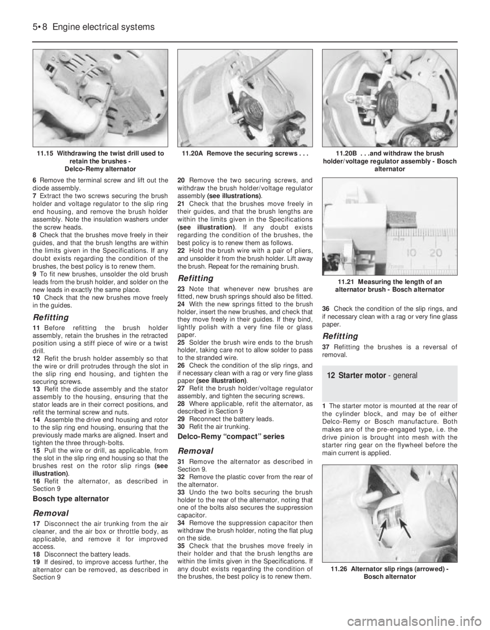
15Pull the wire or drill, as applicable, from
the slot in the slip ring end housing so that the
brushes rest on the rotor slip rings (see
illustration).
16Refit the alternator, as described in
Section 9
Bosch type alternator
Removal
17Disconnect the air trunking from the air
cleaner, and the air box or throttle body, as
applicable, and remove it for improved
access.
18Disconnect the battery leads.
19If desired, to improve access further, the
alternator can be removed, as described in
Section 920Remove the two securing screws, and
withdraw the brush holder/voltage regulator
assembly (see illustrations).
21Check that the brushes move freely in
their guides, and that the brush lengths are
within the limits given in the Specifications
(see illustration). If any doubt exists
regarding the condition of the brushes, the
best policy is to renew them as follows.
22Hold the brush wire with a pair of pliers,
and unsolder it from the brush holder. Lift away
the brush. Repeat for the remaining brush.
Refitting
23Note that whenever new brushes are
fitted, new brush springs should also be fitted.
24With the new springs fitted to the brush
holder, insert the new brushes, and check that
they move freely in their guides. If they bind,
lightly polish with a very fine file or glass
paper.
25Solder the brush wire ends to the brush
holder, taking care not to allow solder to pass
to the stranded wire.
26Check the condition of the slip rings, and
if necessary clean with a rag or very fine glass
paper (see illustration).
27Refit the brush holder/voltage regulator
assembly, and tighten the securing screws.
28Where applicable, refit the alternator, as
described in Section 9
29Reconnect the battery leads.
30Refit the air trunking.
Delco-Remy “compact” series
Removal
31Remove the alternator as described in
Section 9.
32Remove the plastic cover from the rear of
the alternator.
33Undo the two bolts securing the brush
holder to the rear of the alternator, noting that
one of the bolts also secures the suppression
capacitor.
34Remove the suppression capacitor then
withdraw the brush holder, noting the flat plug
on the side.
35Check that the brushes move freely in
their holder and that the brush lengths are
within the limits given in the Specifications. If
any doubt exists regarding the condition of
the brushes, the best policy is to renew them.36Check the condition of the slip rings, and
if necessary clean with a rag or very fine glass
paper.
Refitting
37Refitting the brushes is a reversal of
removal.
12Starter motor - general
1The starter motor is mounted at the rear of
the cylinder block, and may be of either
Delco-Remy or Bosch manufacture. Both
makes are of the pre-engaged type, i.e. the
drive pinion is brought into mesh with the
starter ring gear on the flywheel before the
main current is applied.
5•8Engine electrical systems
11.15 Withdrawing the twist drill used to
retain the brushes -
Delco-Remy alternator11.20B . . .and withdraw the brush
holder/voltage regulator assembly - Bosch
alternator
11.26 Alternator slip rings (arrowed) -
Bosch alternator
11.21 Measuring the length of an
alternator brush - Bosch alternator
11.20A Remove the securing screws . . .
Page 157 of 525
31This engine is also fitted with an EGR
(exhaust gas recirculation) valve and
secondary air injection (AIR - Air Injection
Reactor), to conform to the latest European
exhaust emission limits (as from 1996). The
EGR returns a specific amount of exhaust gas
into the combustion process. This in turn
reduces the formation of nitrogen oxides
(No
x). The secondary air injection system has
an electrically driven air pump that injects air
into the exhaust manifold, reducing the
amount of CO and HC emissions.
2Fuel injection system -
precautions
The fuel injection system is pressurised,
therefore extra care must be taken when
disconnecting fuel lines. When disconnecting
a fuel line union, loosen the union slowly, to
avoid a sudden release of pressure that may
cause fuel to spray out.
Fuel pressure checking must be entrusted
to a Vauxhall dealer, or other specialist, who
has the necessary special equipment.
3System testing - general
3
General
1Apart from basic electrical tests, there is
nothing that can be done by the owner to test
individual fuel system components.2If a fault arises, check first that it is not due
to poor maintenance. Check that the air
cleaner filter element is clean, the spark plugs
are in good condition and correctly gapped.
Check also that the engine breather hoses are
clear and undamaged and that the throttle
cable is correctly adjusted. If the engine is
running very roughly, check the compression
pressures (Chapter 1) and remember the
possibility that one of the hydraulic tappets
might be faulty, producing an incorrect valve
clearance.
3If the fault is thought to be due to a dirty
injector, it is worth trying one of the
established injector-cleaning treatments
before renewing, perhaps unnecessarily, the
injector.
4If the fault persists, check the ignition
system components (as far as possible).
5If the fault is still not eliminated, work
methodically through the system, checking all
fuses, wiring connectors and wiring, looking
for any signs of poor connections, dampness,
corrosion, dirt or other faults.
6Once the system components have been
checked for signs of obvious faults, take the
vehicle to a Vauxhall dealer for the full system
to be tested on special equipment.
7Do not attempt to “test” any component,
but particularly the ECU, with anything other
than the correct test equipment, available at a
Vauxhall dealer. If any of the wires to be
checked lead to a component such as the
ECU, always first unplug the relevant
connector from the system components so
that there is no risk of the component being
damaged by the application of incorrect
voltages from test equipment.
4Air cleaner - removal and
refitting
2
Note:If ‘round type’ air filter is fitted, follow
procedure in Chapter 4A.
Removal
1Unclip the coolant expansion tank hose
from the air cleaner cover, and move it to one
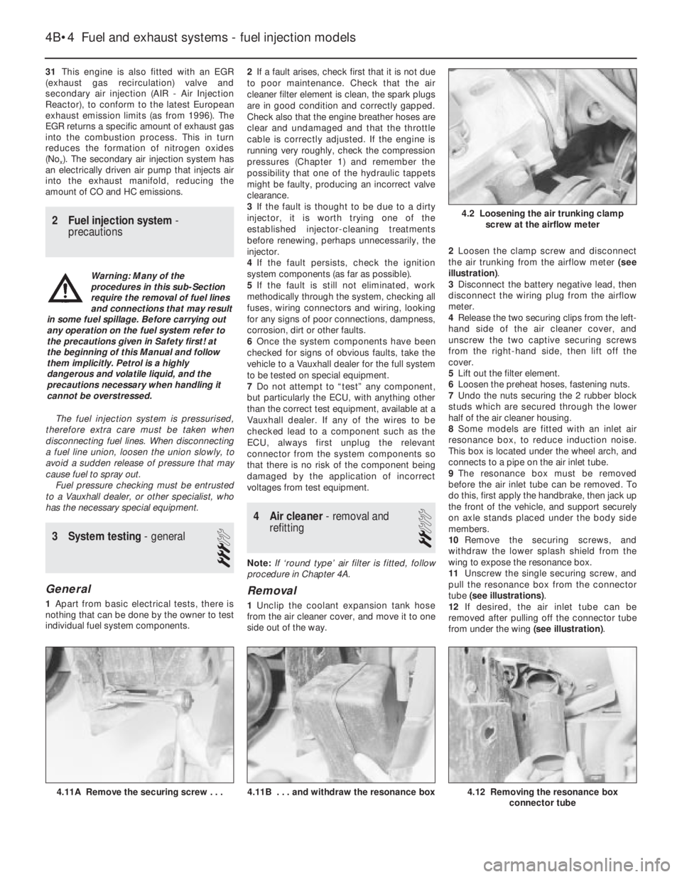
side out of the way.2Loosen the clamp screw and disconnect
the air trunking from the airflow meter (see
illustration).
3Disconnect the battery negative lead, then
disconnect the wiring plug from the airflow
meter.
4Release the two securing clips from the left-
hand side of the air cleaner cover, and
unscrew the two captive securing screws
from the right-hand side, then lift off the
cover.
5Lift out the filter element.
6Loosen the preheat hoses, fastening nuts.
7Undo the nuts securing the 2 rubber block
studs which are secured through the lower
half of the air cleaner housing.
8Some models are fitted with an inlet air
resonance box, to reduce induction noise.
This box is located under the wheel arch, and
connects to a pipe on the air inlet tube.
9The resonance box must be removed
before the air inlet tube can be removed. To
do this, first apply the handbrake, then jack up
the front of the vehicle, and support securely
on axle stands placed under the body side
members.
10Remove the securing screws, and
withdraw the lower splash shield from the
wing to expose the resonance box.
11Unscrew the single securing screw, and
pull the resonance box from the connector
tube (see illustrations).
12If desired, the air inlet tube can be
removed after pulling off the connector tube
from under the wing (see illustration).
4B•4Fuel and exhaust systems - fuel injection models
4.12 Removing the resonance box
connector tube4.11B . . . and withdraw the resonance box4.11A Remove the securing screw . . .
4.2 Loosening the air trunking clamp
screw at the airflow meter
Warning: Many of the
procedures in this sub-Section
require the removal of fuel lines
and connections that may result
in some fuel spillage. Before carrying out
any operation on the fuel system refer to
the precautions given in Safety first! at
the beginning of this Manual and follow
them implicitly. Petrol is a highly
dangerous and volatile liquid, and the
precautions necessary when handling it
cannot be overstressed.