1988 OPEL VECTRA reset
[x] Cancel search: resetPage 20 of 525
3To remove the cigarette lighter assembly,
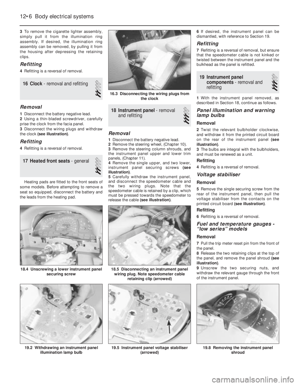
simply pull it from the illumination ring
assembly. If desired, the illumination ring
assembly can be removed, by pulling it from
the housing after depressing the retaining
clips.
Refitting
4Refitting is a reversal of removal.
16Clock - removal and refitting
2
Removal
1Disconnect the battery negative lead.
2Using a thin-bladed screwdriver, carefully
prise the clock from the facia panel.
3Disconnect the wiring plugs and withdraw
the clock (see illustration).
Refitting
4Refitting is a reversal of removal.
17Heated front seats - general
2
Heating pads are fitted to the front seats of
some models. Before attempting to remove a
seat so equipped, disconnect the battery and
the leads from the heating pad.
18Instrument panel -removal
and refitting
3
Removal
1Disconnect the battery negative lead.
2Remove the steering wheel, (Chapter 10).
3Remove the steering column shrouds, and
the instrument panel upper and lower trim
panels, (Chapter 11).
4Remove the single upper, and two lower,
instrument panel securing screws (see
illustration).
5Carefully withdraw the instrument panel,
and disconnect the speedometer cable and
the two wiring plugs. Note that the
speedometer cable is retained by a clip, which
must be pressed towards the speedometer to
release the cable (see illustration).6If desired, the instrument panel can be
dismantled, with reference to Section 19.
Refitting
7Refitting is a reversal of removal, but ensure
that the speedometer cable is not kinked or
twisted between the instrument panel and the
bulkhead as the panel is refitted.
19Instrument panel
components - removal and
refitting
3
1With the instrument panel removed, as
described in Section 18, continue as follows.
Panel illumination and warning
lamp bulbs
Removal
2Twist the relevant bulbholder clockwise,
and withdraw it from the printed circuit board
on the rear of the instrument panel (see
illustration).
3The bulbs are integral with the bulbholders,
and must be renewed as a unit.
Refitting
4Refitting is a reversal of removal.
Voltage stabiliser
Removal
5Remove the single securing screw from the
rear of the instrument panel, then pull the
voltage stabiliser from the contacts on the
printed circuit board (see illustration).
Refitting
6Refitting is a reversal of removal.
Fuel and temperature gauges -
“low series” models
Removal
7Pull the trip meter reset pin from the front of
the panel.
8Release the two retaining clips at the top of
the panel, and remove the panel shroud (see
illustration).
9Unscrew the two securing nuts, and
withdraw the relevant gauge through the front
of the instrument panel.
12•6Body electrical systems
16.3 Disconnecting the wiring plugs from
the clock
18.5 Disconnecting an instrument panel
wiring plug. Note speedometer cable
retaining clip (arrowed)
19.8 Removing the instrument panel
shroud19.5 Instrument panel voltage stabiliser
(arrowed)19.2 Withdrawing an instrument panel
illumination lamp bulb
18.4 Unscrewing a lower instrument panel
securing screw
Page 39 of 525
Wiring diagrams 12•25
12
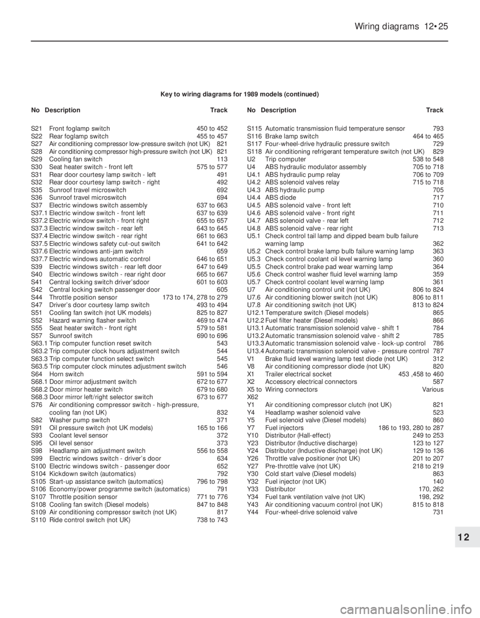
Key to wiring diagrams for 1989 models (continued)
S21Front foglamp switch450 to 452
S22Rear foglamp switch455 to 457
S27Air conditioning compressor low-pressure switch (not UK)821
S28Air conditioning compressor high-pressure switch (not UK)821
S29Cooling fan switch113
S30Seat heater switch - front left575 to 577
S31Rear door courtesy lamp switch - left491
S32Rear door courtesy lamp switch - right492
S35Sunroof travel microswitch692
S36Sunroof travel microswitch694
S37Electric windows switch assembly637 to 663
S37.1Electric window switch - front left637 to 639
S37.2Electric window switch - front right655 to 657
S37.3Electric window switch - rear left643 to 645
S37.4Electric window switch - rear right661 to 663
S37.5Electric windows safety cut-out switch641 to 642
S37.6Electric windows anti-jam switch659
S37.7Electric windows automatic control646 to 651
S39Electric windows switch - rear left door647 to 649
S40Electric windows switch - rear right door665 to 667
S41Central locking switch driver’sdoor601 to 603
S42Central locking switch passenger door605
S44Throttle position sensor173 to 174, 278 to 279
S47Driver’s door courtesy lamp switch493 to 494
S51Cooling fan switch (not UK models)825 to 827
S52Hazard warning flasher switch469 to 474
S55Seat heater switch - front right579 to 581
S57Sunroof switch690 to 696
S63.1Trip computer function reset switch543
S63.2Trip computer clock hours adjustment switch544
S63.3Trip computer function select switch545
S63.5Trip computer clock minutes adjustment switch546
S64Horn switch591 to 594
S68.1Door mirror adjustment switch672 to 677
S68.2Door mirror heater switch679 to 680
S68.3Door mirror left/right selector switch673 to 677
S76Air conditioning compressor switch -high-pressure,
cooling fan (not UK)832
S82Washer pump switch371
S91Oil pressure switch (not UK models)165 to 166
S93Coolant level sensor372
S95Oil level sensor373
S98Headlamp aim adjustment switch556 to 558
S99Electric windows switch - driver’s door634
S100Electric windows switch -passenger door652
S104Kickdown switch (automatics)792
S105Start-up assistance switch (automatics)796 to 798
S106Economy/power programme switch (automatics)791
S107Throttle position sensor 771 to 776
S108Cooling fan switch (Diesel models)847 to 848
S109Air conditioning compressor switch (not UK)817
S110Ride control switch (not UK)738 to 743S115Automatic transmission fluid temperature sensor793
S116Brake lamp switch464 to 465
S117Four-wheel-drive hydraulic pressure switch729
S118Air conditioning refrigerant temperature switch (not UK)829
U2Trip computer538 to 548
U4ABS hydraulic modulator assembly705 to 718
U4.1ABS hydraulic pump relay706 to 709
U4.2ABS solenoid valves relay715 to 718
U4.3ABS hydraulic pump705
U4.4ABS diode717
U4.5ABS solenoid valve - front left710
U4.6ABS solenoid valve - front right711
U4.7ABS solenoid valve - rear left712
U4.8ABS solenoid valve - rear right713
U5.1Check control tail lamp and dipped beam bulb failure
warning lamp362
U5.2Check control brake lamp bulb failure warning lamp 363
U5.3Check control coolant oil level warning lamp360
U5.5Check control brake pad wear warning lamp364
U5.6Check control washer fluid level warning lamp359
U5.7Check control coolant level warning lamp361
U7Air conditioning control unit (not UK)806 to 824
U7.6Air conditioning blower switch (not UK)806 to 811
U7.8Air conditioning switch (not UK)813 to 824
U12.1Temperature switch (Diesel models)865
U12.2Fuel filter heater (Diesel models)866
U13.1Automatic transmission solenoid valve -shift 1784
U13.2Automatic transmission solenoid valve - shift 2785
U13.3Automatic transmission solenoid valve - lock-up control786
U13.4Automatic transmission solenoid valve - pressure control787
V1Brake fluid level warning lamp test diode (not UK)312
V8 Air conditioning compressor diode (not UK)820
X1Trailer electrical socket453 ,458 to 460
X2Accessory electrical connectors587
X5 toWiring connectorsVarious
X62
Y1Air conditioning compressor clutch (not UK)821
Y4Headlamp washer solenoid valve523
Y5Fuel solenoid valve (Diesel models)860
Y7Fuel injectors186 to 193, 280 to 287
Y10Distributor (Hall-effect)249 to 253
Y23Distributor (Inductive discharge)123 to 127
Y24Distributor (Inductive discharge) (not UK)129 to 136
Y26Throttle valve positioner (not UK)201 to 207
Y27Pre-throttle valve (not UK)218 to 219
Y30Cold start valve (Diesel models)863
Y32Fuel injector (not UK)140
Y33Distributor170, 262
Y34Fuel tank ventilation valve (not UK)198, 292
Y43Air conditioning vacuum control (not UK)815 to 818
Y44Four-wheel-drive solenoid valve731 NoDescriptionTrackNoDescriptionTrack
Page 54 of 525
12•40Wiring diagrams
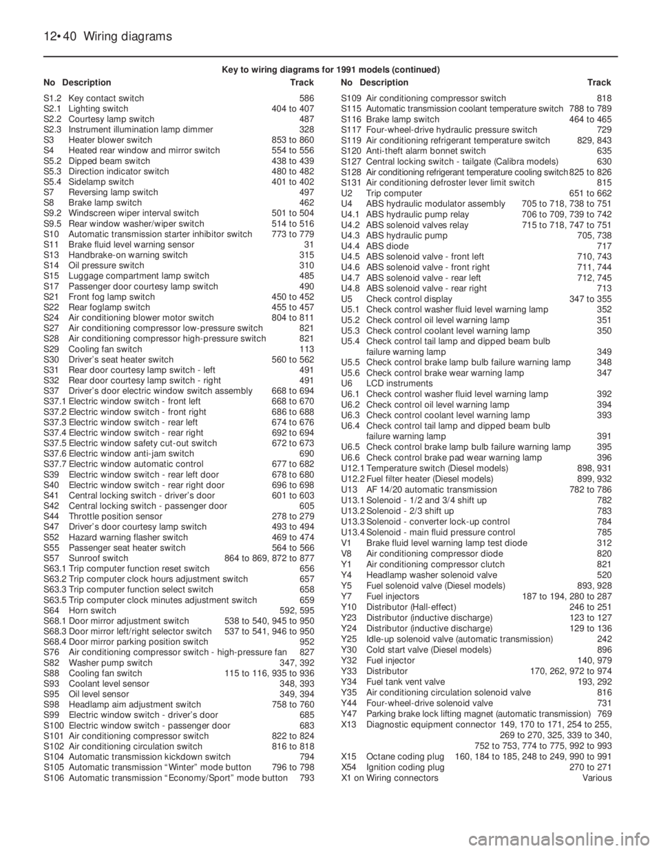
Key to wiring diagrams for 1991 models (continued)
NoDescriptionTrackNoDescriptionTrack
S1.2Key contact switch586
S2.1Lighting switch404 to 407
S2.2Courtesy lamp switch487
S2.3Instrument illumination lamp dimmer328
S3Heater blower switch853 to 860
S4Heated rear window and mirror switch554 to 556
S5.2Dipped beam switch438 to 439
S5.3Direction indicator switch480 to 482
S5.4Sidelamp switch401 to 402
S7Reversing lamp switch497
S8Brake lamp switch462
S9.2Windscreen wiper interval switch501 to 504
S9.5Rear window washer/wiper switch514 to 516
S10Automatic transmission starter inhibitor switch773 to 779
S11Brake fluid level warning sensor31
S13Handbrake-on warning switch315
S14Oil pressure switch310
S15Luggage compartment lamp switch485
S17Passenger door courtesy lamp switch490
S21Front fog lamp switch450 to 452
S22Rear foglamp switch455 to 457
S24Air conditioning blower motor switch804 to 811
S27Air conditioning compressor low-pressure switch821
S28Air conditioning compressor high-pressure switch821
S29Cooling fan switch113
S30Driver’s seat heater switch560 to 562
S31Rear door courtesy lamp switch - left491
S32Rear door courtesy lamp switch - right491
S37Driver’s door electric window switch assembly668 to 694
S37.1Electric window switch - front left668 to 670
S37.2Electric window switch - front right686 to 688
S37.3Electric window switch - rear left674 to 676
S37.4Electric window switch - rear right692 to 694
S37.5Electric window safety cut-out switch672 to 673
S37.6Electric window anti-jam switch690
S37.7Electric window automatic control677 to 682
S39Electric window switch - rear left door678 to 680
S40Electric window switch - rear right door696 to 698
S41Central locking switch - driver’s door601 to 603
S42Central locking switch - passenger door605
S44Throttle position sensor278 to 279
S47Driver’s door courtesy lamp switch493 to 494
S52Hazard warning flasher switch469 to 474
S55Passenger seat heater switch564 to 566
S57Sunroof switch864 to 869, 872 to 877
S63.1Trip computer function reset switch656
S63.2Trip computer clock hours adjustment switch657
S63.3Trip computer function select switch658
S63.5Trip computer clock minutes adjustment switch659
S64Horn switch592, 595
S68.1Door mirror adjustment switch538 to 540, 945 to 950
S68.3Door mirror left/right selector switch537 to 541, 946 to 950
S68.4Door mirror parking position switch952
S76Air conditioning compressor switch - high-pressure fan827
S82Washer pump switch347, 392
S88Cooling fan switch115 to 116, 935 to 936
S93Coolant level sensor348, 393
S95Oil level sensor349, 394
S98Headlamp aim adjustment switch758 to 760
S99Electric window switch - driver’s door685
S100Electric window switch - passenger door683
S101Air conditioning compressor switch822 to 824
S102Air conditioning circulation switch816 to 818
S104Automatic transmission kickdown switch794
S105Automatic transmission “Winter” mode button796 to 798
S106Automatic transmission “Economy/Sport” mode button793S109Air conditioning compressor switch818
S115Automatic transmission coolant temperature switch788 to 789
S116Brake lamp switch464 to 465
S117Four-wheel-drive hydraulic pressure switch729
S119Air conditioning refrigerant temperature switch829, 843
S120Anti-theft alarm bonnet switch635
S127Central locking switch - tailgate (Calibra models)630
S128Air conditioning refrigerant temperature cooling switch825 to 826
S131Air conditioning defroster lever limit switch815
U2Trip computer651 to 662
U4ABS hydraulic modulator assembly705 to 718, 738 to 751
U4.1ABS hydraulic pump relay706 to 709, 739 to 742
U4.2ABS solenoid valves relay715 to 718, 747 to 751
U4.3ABS hydraulic pump705, 738
U4.4ABS diode717
U4.5ABS solenoid valve - front left710, 743
U4.6ABS solenoid valve - front right711, 744
U4.7ABS solenoid valve - rear left712, 745
U4.8ABS solenoid valve - rear right713
U5Check control display347 to 355
U5.1Check control washer fluid level warning lamp352
U5.2Check control oil level warning lamp351
U5.3Check control coolant level warning lamp350
U5.4Check control tail lamp and dipped beam bulb
failure warning lamp349
U5.5Check control brake lamp bulb failure warning lamp348
U5.6Check control brake wear warning lamp347
U6LCD instruments
U6.1Check control washer fluid level warning lamp392
U6.2Check control oil level warning lamp394
U6.3Check control coolant level warning lamp393
U6.4Check control tail lamp and dipped beam bulb
failure warning lamp391
U6.5Check control brake lamp bulb failure warning lamp395
U6.6Check control brake pad wear warning lamp396
U12.1Temperature switch (Diesel models)898, 931
U12.2Fuel filter heater (Diesel models)899, 932
U13AF14/20automatic transmission782 to 786
U13.1Solenoid - 1/2 and 3/4 shift up782
U13.2Solenoid - 2/3 shift up783
U13.3Solenoid - converter lock-up control784
U13.4Solenoid - main fluid pressure control785
V1Brake fluid level warning lamp test diode312
V8Air conditioning compressor diode820
Y1Air conditioning compressor clutch821
Y4Headlamp washer solenoid valve520
Y5Fuel solenoid valve (Diesel models)893, 928
Y7Fuel injectors187 to 194, 280 to 287
Y10Distributor (Hall-effect)246 to 251
Y23Distributor (inductive discharge)123 to 127
Y24Distributor (inductive discharge)129 to 136
Y25Idle-up solenoid valve (automatic transmission)242
Y30Cold start valve (Diesel models)896
Y32Fuel injector140, 979
Y33Distributor170, 262, 972 to 974
Y34Fuel tank vent valve193, 292
Y35Air conditioning circulation solenoid valve816
Y44Four-wheel-drive solenoid valve731
Y47Parking brake lock lifting magnet (automatic transmission)769
X13Diagnostic equipment connector149, 170 to 171, 254 to 255,
269 to 270, 325, 339 to 340,
752 to 753, 774 to 775, 992 to 993
X15Octane coding plug160, 184 to 185, 248 to 249, 990 to 991
X54Ignition coding plug270 to 271
X1 onWiring connectorsVarious
Page 71 of 525
Wiring diagrams 12•57
12
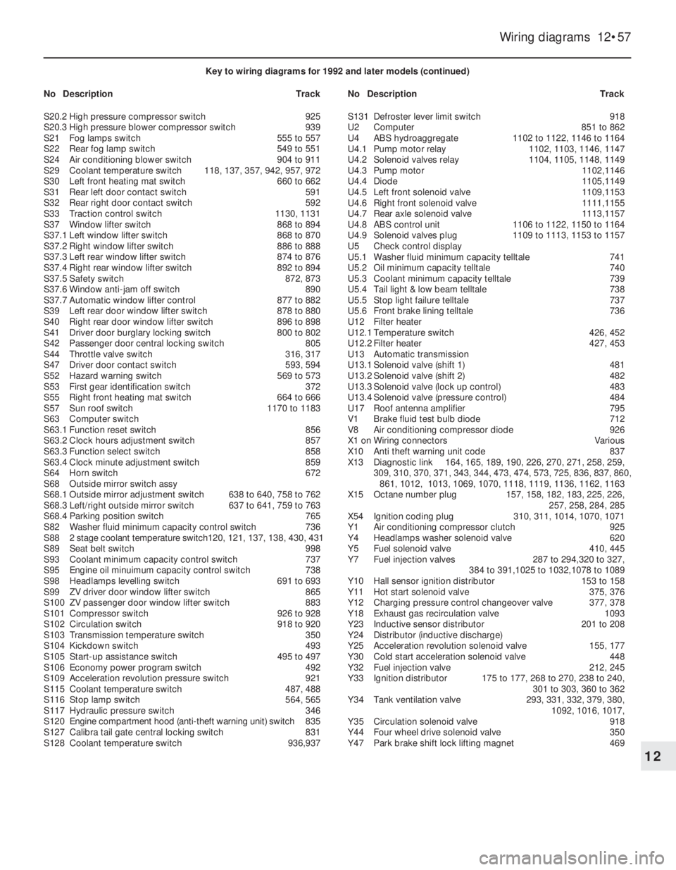
Key to wiring diagrams for 1992 and later models (continued)
NoDescriptionTrackNoDescriptionTrack
S20.2High pressure compressor switch925
S20.3High pressure blower compressor switch939
S21Fog lamps switch555 to 557
S22Rear fog lamp switch549 to 551
S24Air conditioning blower switch904 to 911
S29Coolant temperature switch118, 137, 357, 942, 957, 972
S30Left front heating mat switch660 to 662
S31Rear left door contact switch591
S32Rear right door contact switch592
S33Traction control switch1130, 1131
S37Window lifter switch868 to 894
S37.1Left window lifter switch868 to 870
S37.2Right window lifter switch886 to 888
S37.3Left rear window lifter switch874 to 876
S37.4Right rear window lifter switch892 to 894
S37.5Safety switch872, 873
S37.6Window anti-jam off switch890
S37.7Automatic window lifter control877 to 882
S39Left rear door window lifter switch878 to 880
S40Right rear door window lifter switch896 to 898
S41Driver door burglary locking switch800 to 802
S42Passenger door central locking switch805
S44Throttle valve switch316, 317
S47Driver door contact switch593, 594
S52Hazard warning switch569 to 573
S53First gear identification switch372
S55Right front heating mat switch664 to 666
S57Sun roof switch1170 to 1183
S63Computer switch
S63.1Function reset switch856
S63.2Clock hours adjustment switch857
S63.3Function select switch858
S63.4Clock minute adjustment switch859
S64Horn switch672
S68Outside mirror switch assy
S68.1Outside mirror adjustment switch638 to 640, 758 to 762
S68.3Left/right outside mirror switch637 to 641, 759 to 763
S68.4Parking position switch765
S82Washer fluid minimum capacity control switch736
S882 stage coolant temperature switch120, 121, 137, 138, 430, 431
S89Seat belt switch998
S93Coolant minimum capacity control switch737
S95Engine oil minuimum capacity control switch738
S98Headlamps levelling switch691 to 693
S99ZV driver door window lifter switch865
S100ZV passenger door window lifter switch883
S101Compressor switch926 to 928
S102Circulation switch918 to 920
S103Transmission temperature switch350
S104Kickdown switch493
S105Start-up assistance switch495 to 497
S106Economy power program switch492
S109Acceleration revolution pressure switch921
S115Coolant temperature switch487, 488
S116Stop lamp switch564, 565
S117Hydraulic pressure switch346
S120Engine compartment hood (anti-theft warning unit) switch835
S127Calibra tail gate central locking switch831
S128Coolant temperature switch936,937S131Defroster lever limit switch918
U2Computer851 to 862
U4ABS hydroaggregate1102 to 1122, 1146 to 1164
U4.1Pump motor relay1102, 1103, 1146, 1147
U4.2Solenoid valves relay1104, 1105, 1148, 1149
U4.3Pump motor1102,1146
U4.4Diode1105,1149
U4.5Left front solenoid valve1109,1153
U4.6Right front solenoid valve1111,1155
U4.7Rear axle solenoid valve1113,1157
U4.8ABS control unit1106 to 1122, 1150 to 1164
U4.9Solenoid valves plug1109 to 1113, 1153 to 1157
U5Check control display
U5.1Washer fluid minimum capacity telltale741
U5.2Oil minimum capacity telltale740
U5.3Coolant minimum capacity telltale739
U5.4Tail light & low beam telltale738
U5.5Stop light failure telltale737
U5.6Front brake lining telltale736
U12Filter heater
U12.1Temperature switch426, 452
U12.2Filter heater427, 453
U13Automatic transmission
U13.1Solenoid valve (shift 1)481
U13.2Solenoid valve (shift 2)482
U13.3Solenoid valve (lock up control)483
U13.4Solenoid valve (pressure control)484
U17Roof antenna amplifier795
V1Brake fluid test bulb diode712
V8Air conditioning compressor diode926
X1 onWiring connectorsVarious
X10Anti theft warning unit code837
X13Diagnostic link164, 165, 189, 190, 226, 270, 271, 258, 259,
309, 310, 370, 371, 343, 344, 473, 474, 573, 725, 836, 837, 860,
861, 1012, 1013, 1069, 1070, 1118, 1119, 1136, 1162, 1163
X15Octane number plug157, 158, 182, 183, 225, 226,
257, 258, 284, 285
X54Ignition coding plug310, 311, 1014, 1070, 1071
Y1Air conditioning compressor clutch925
Y4Headlamps washer solenoid valve620
Y5Fuel solenoid valve410, 445
Y7Fuel injection valves287 to 294,320 to 327,
384 to 391,1025 to 1032,1078 to 1089
Y10Hall sensor ignition distributor153 to 158
Y11Hot start solenoid valve375, 376
Y12Charging pressure control changeover valve377, 378
Y18Exhaust gas recirculation valve1093
Y23Inductive sensor distributor201 to 208
Y24Distributor (inductive discharge)
Y25Acceleration revolution solenoid valve155, 177
Y30Cold start acceleration solenoid valve 448
Y32Fuel injection valve212, 245
Y33Ignition distributor175 to 177, 268 to 270, 238 to 240,
301 to 303, 360 to 362
Y34Tank ventilation valve293, 331, 332, 379, 380,
1092, 1016, 1017,
Y35Circulation solenoid valve918
Y44Four wheel drive solenoid valve350
Y47Park brake shift lock lifting magnet469
Page 125 of 525
3The tensioner assembly, fitted to the
underside of the front seat, is maintenance
free and, once triggered, must be replaced as
a complete unit.
4Due to the specialist safety related nature
of the seat belt tensioner system, replacement
must be entrusted to a suitably equipped
Vauxhall dealer.
43Front seats (with seat belt
tensioners) -removal and
refitting
3
Removal
1Remove the single securing screw from the
front edge of the outer seat rail trim, release
the rear retaining lug and remove the trim
rearwards.
2Unclip the trim from the rear edge of the
inner seat rail.3Locate the plastic safety fork for the seat
belt tensioner, which is usually taped to the
outside of the tensioner spring cylinder.
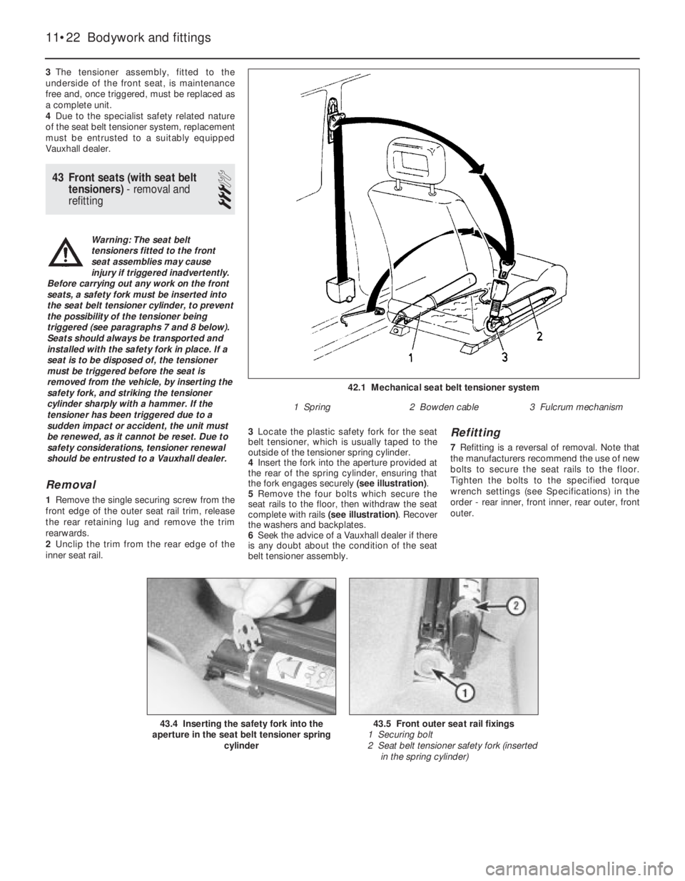
4Insert the fork into the aperture provided at
the rear of the spring cylinder, ensuring that
the fork engages securely (see illustration).
5Remove the four bolts which secure the
seat rails to the floor, then withdraw the seat
complete with rails (see illustration). Recover
the washers and backplates.
6Seek the advice of a Vauxhall dealer if there
is any doubt about the condition of the seat
belt tensioner assembly.
Refitting
7Refitting is a reversal of removal. Note that
the manufacturers recommend the use of new
bolts to secure the seat rails to the floor.
Tighten the bolts to the specified torque
wrench settings (see Specifications) in the
order - rear inner, front inner, rear outer, front
outer.
11•22Bodywork and fittings
42.1 Mechanical seat belt tensioner system
1 Spring2 Bowden cable3 Fulcrum mechanism
43.5 Front outer seat rail fixings
1 Securing bolt
2 Seat belt tensioner safety fork (inserted
in the spring cylinder)43.4 Inserting the safety fork into the
aperture in the seat belt tensioner spring
cylinder
Warning: The seat belt
tensioners fitted to the front
seat assemblies may cause
injury if triggered inadvertently.
Before carrying out any work on the front
seats, a safety fork must be inserted into
the seat belt tensioner cylinder, to prevent
the possibility of the tensioner being
triggered (see paragraphs 7 and 8 below).
Seats should always be transported and
installed with the safety fork in place. If a
seat is to be disposed of, the tensioner
must be triggered before the seat is
removed from the vehicle, by inserting the
safety fork, and striking the tensioner
cylinder sharply with a hammer. If the
tensioner has been triggered due to a
sudden impact or accident, the unit must
be renewed, as it cannot be reset. Due to
safety considerations, tensioner renewal
should be entrusted to a Vauxhall dealer.
Page 162 of 525
4B
4Clamp the fuel hoses on either side of the
damper, to minimise fuel loss when the hoses
are disconnected.
5Loosen the clamp screws, and disconnect
the fuel hoses from the damper. Be prepared
for fuel spillage, and take adequate fire
precautions.
6Unscrew the securing nut, and withdraw
the damper from the bracket.
Refitting
7Refitting is a reversal of removal.
8Run the engine and check for leaks on
completion. If leakage is evident; stop the
engine immediately, and rectify the problem
without delay.
19Throttle cable - removal,
refitting and adjustment
3
Removal
1This procedure is basically the same as
described in Chapter 4A, but note the
following.
2Not all models are fitted with an air box.
Ignore references to it, if not applicable.
3For “carburettor” substitute “throttle body”,
and note that the cable bracket is bolted to
the inlet manifold.
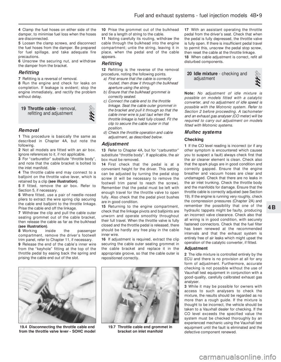
4The throttle cable end may connect to a
balljoint on the throttle valve lever, which is
retained by a clip (see illustration).
5If fitted, remove the air box. Refer to
Section 5, if necessary.
6Where fitted, use a pair of needle-nosed
pliers to extract the wire spring clip securing
the cable end balljoint to the throttle linkage.
Prise the cable end off the linkage.
7Withdraw the clip and pull the cable outer
seating grommet out of the cable bracket,
then release the cable as far as the bulkhead
(see illustration).
8Working inside the passenger
compartment, remove the driver’s footwell
trim panel, refer to Chapter 11, if necessary.
9Release the end of the cable’s inner wire
from the “keyhole” fitting at the top of the
throttle pedal by easing back the spring and
prising the cable end out of the slot.10Prise the grommet out of the bulkhead
and tie a length of string to the cable.
11Noting carefully its routing, withdraw the
cable through the bulkhead into the engine
compartment; untie the string, leaving it in
place, when the pedal end of the cable
appears.
Refitting
12Refitting is the reverse of the removal
procedure, noting the following points.
a)First ensure that the cable is correctly
routed, then draw it through the bulkhead
aperture using the string.
b)Ensure that the bulkhead grommet is
correctly seated.
c)Connect the cable end to the throttle
linkage. Seat the cable outer grommet in
the bracket and pull it through so that the
cable inner wire is just taut when the
throttle linkage is held fully closed. Fit the
clip to secure the cable outer in that
position.
d)Check the throttle operation and cable
adjustment, as described below.
Adjustment
13Refer to Chapter 4A, but for “carburettor”
substitute “throttle body”. If applicable, the air
box must be removed.
14First check that the pedal is at a
convenient height for the driver. This setting
can be adjusted by turning the pedal stop
screw (it will be necessary to remove the
footwell trim panel to reach the screw).
Remember that the pedal must be left with
enough travel for the throttle valve to open
fully. Also check that the pedal pivot bushes
are in good condition.
15Returning to the engine compartment,
check that the linkage pivots and balljoints are
unworn and operate smoothly throughout
their full travel. When the throttle valve is fully
closed and the throttle pedal is released, there
should be hardly any free play in the cable
inner wire.
16If adjustment is required, extract the clip
securing the cable outer seating grommet in
the cable bracket and replace it in the
appropriate groove, so that the cable outer is
repositioned correctly.17With an assistant operating the throttle
pedal from the driver’s seat. Check that when
the pedal is fully depressed, the throttle valve
is fully open. If there is insufficient pedal travel
to permit this, unscrew the pedal stop screw,
then reset the cable at the throttle linkage.
18When cable adjustment is correct, refit all
disturbed components.
20Idle mixture - checking and
adjustment
3
Note: No adjustment of idle mixture is
possible on models fitted with a catalytic
converter, and no adjustment of idle speed is
possible with the Motronic system. Refer to
Section 2 before proceeding. A tachometer
and an exhaust gas analyser (CO meter) will be
required to carry out adjustment on models
fitted with Motronic systems.
Multec systems
Checking
1If the CO level reading is incorrect (or if any
other symptom is encountered which causes
you to suspect a fault) always check first that
the air cleaner element is clean. Check also
that the spark plugs are in good condition and
correctly gapped. Ensure that the engine
breather and vacuum hoses are clear and
undamaged. Check that there are no leaks in
the air inlet trunking. Check the throttle body
and the manifolds for damage. Ensure that the
throttle cable is correctly adjusted (see Section
19). If the engine is running very roughly, check
the compression pressures (Chapter 2A) and
remember the possibility that one of the
hydraulic tappets might be faulty, producing
an incorrect valve clearance. Check also that
all wiring is in good condition, with securely
fastened connectors. Check that the fuel filter
has been renewed at the recommended
intervals and that the exhaust system is
entirely free of air leaks which might upset the
operation of the catalytic converter, if fitted.
Adjustment
2The idle mixture is controlled entirely by the
ECU and there is no provision at all for any
form of adjustment. Furthermore, accurate
checking is not possible without the use of
Vauxhall test equipment in conjunction with a
good-quality, carefully calibrated exhaust gas
analyser.
3While it may be possible for owners with
access to such analysers to check the
mixture, the results should be regarded as no
more than a rough guide. If the mixture is
thought to be incorrect, the vehicle should be
taken to a Vauxhall dealer for checking. If the
CO level exceeds the specified value the
system must be checked thoroughly by an
experienced mechanic using the Vauxhall test
equipment until the fault is eliminated and the
defective component renewed.
Fuel and exhaust systems - fuel injection models 4B•9
19.7 Throttle cable end grommet in
bracket on inlet manifold19.4 Disconnecting the throttle cable end
from the throttle valve lever - SOHC model
Page 169 of 525
b)Check the throttle cable operation and
adjustment (see above).
c)When reconnecting the vacuum hoses
and pipes, ensure that they are connected
to the front unions as shown in the
accompanying photograph.
d)As no fuel vapour trap is fitted, it is
essential that the manifold absolute
pressure sensor vacuum hose is routed
so that it falls steadily from the sensor to
the throttle body. This precaution will
prevent any fuel droplets being trapped in
the sensor or hose and allowing them to
drain into the inlet port.
e)Ensure that the fuel hoses are correctly
reconnected; the feed hose is on the
injector end of the throttle body.
f)Switch on the ignition and check for signs
of fuel leaks from all disturbed unions; if
any signs of leakage are detected, the
problem must be rectified before the
engine is started.
33Idle air control stepper
motor - removal and refitting
3
Removal
1Remove the air box (see Section 5).
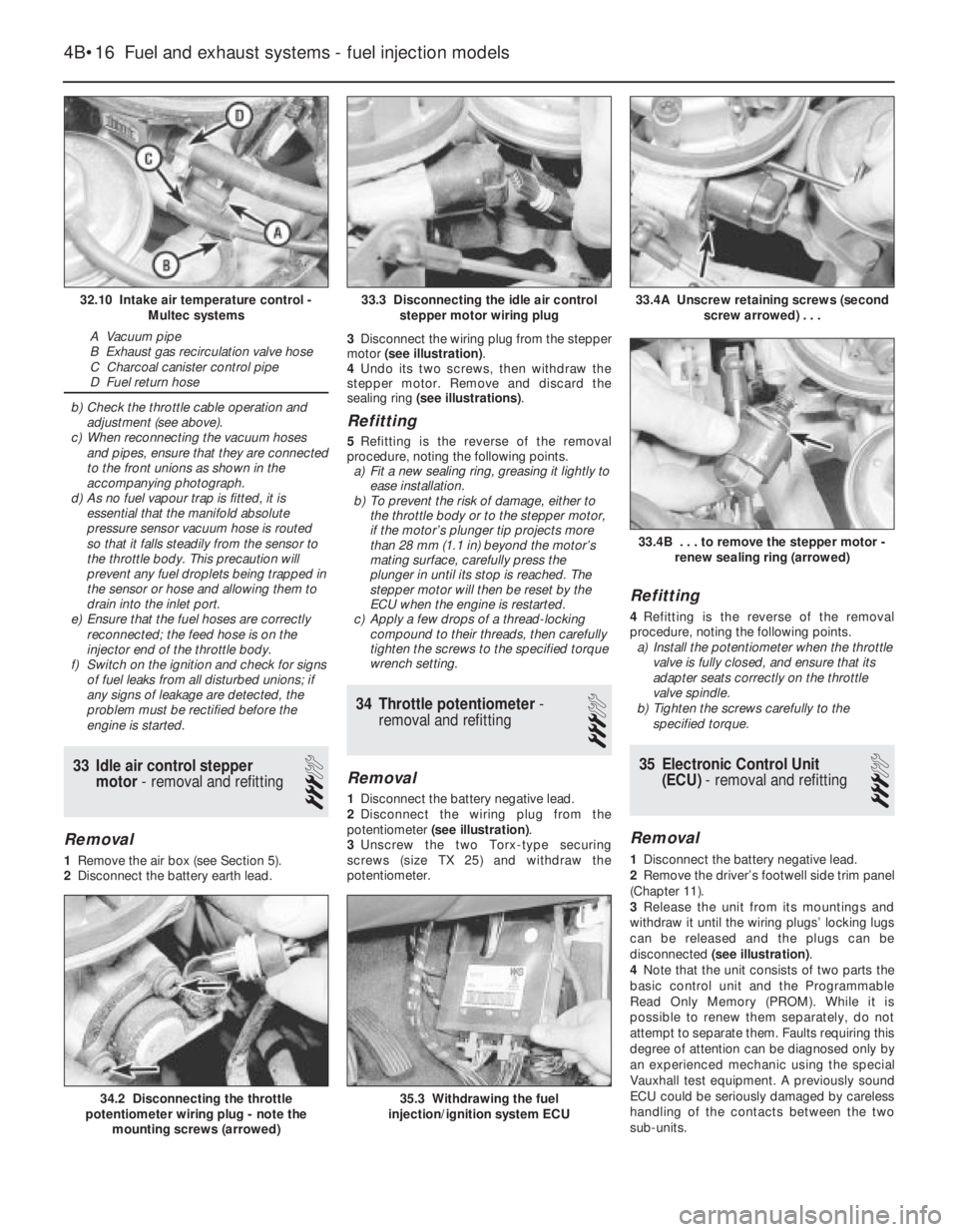
2Disconnect the battery earth lead.3Disconnect the wiring plug from the stepper
motor (see illustration).
4Undo its two screws, then withdraw the
stepper motor. Remove and discard the
sealing ring (see illustrations).
Refitting
5Refitting is the reverse of the removal
procedure, noting the following points.
a)Fit a new sealing ring, greasing it lightly to
ease installation.
b)To prevent the risk of damage, either to
the throttle body or to the stepper motor,
if the motor’s plunger tip projects more
than 28 mm (1.1 in) beyond the motor’s
mating surface, carefully press the
plunger in until its stop is reached. The
stepper motor will then be reset by the
ECU when the engine is restarted.
c)Apply a few drops of a thread-locking
compound to their threads, then carefully
tighten the screws to the specified torque
wrench setting.
34Throttle potentiometer -
removal and refitting
3
Removal
1Disconnect the battery negative lead.
2Disconnect the wiring plug from the
potentiometer (see illustration).
3Unscrew the two Torx-type securing
screws (size TX 25) and withdraw the
potentiometer.
Refitting
4Refitting is the reverse of the removal
procedure, noting the following points.
a)Install the potentiometer when the throttle
valve is fully closed, and ensure that its
adapter seats correctly on the throttle
valve spindle.
b)Tighten the screws carefully to the
specified torque.
35Electronic Control Unit
(ECU) - removal and refitting
3
Removal
1Disconnect the battery negative lead.
2Remove the driver’s footwell side trim panel
(Chapter 11).
3Release the unit from its mountings and
withdraw it until the wiring plugs’ locking lugs
can be released and the plugs can be
disconnected (see illustration).
4Note that the unit consists of two parts the
basic control unit and the Programmable
Read Only Memory (PROM). While it is
possible to renew them separately, do not
attempt to separate them. Faults requiring this
degree of attention can be diagnosed only by
an experienced mechanic using the special
Vauxhall test equipment. A previously sound
ECU could be seriously damaged by careless
handling of the contacts between the two
sub-units.
4B•16Fuel and exhaust systems - fuel injection models
32.10 Intake air temperature control -
Multec systems
A Vacuum pipe
B Exhaust gas recirculation valve hose
C Charcoal canister control pipe
D Fuel return hose
33.4A Unscrew retaining screws (second
screw arrowed) . . .
35.3 Withdrawing the fuel
injection/ignition system ECU34.2 Disconnecting the throttle
potentiometer wiring plug - note the
mounting screws (arrowed)
33.4B . . . to remove the stepper motor -
renew sealing ring (arrowed)
33.3 Disconnecting the idle air control
stepper motor wiring plug