1988 OPEL VECTRA recommended oil
[x] Cancel search: recommended oilPage 17 of 525
to-metal contact between components, due
to flexible rubber mountings, etc.
To check whether a component is properly
earthed, disconnect the battery, and connect
one lead of an ohmmeter to a known good
earth point. Connect the other lead to the wire
or earth connection being tested. The
resistance reading should be zero; if not,
check the connection as follows.
If an earth connection is thought to be
faulty, dismantle the connection, and clean
back to bare metal both the bodyshell and the
wire terminal or the component earth
connection mating surface. Be careful to
remove all traces of dirt and corrosion, then
use a knife to trim away any paint, so that a
clean metal-to-metal joint is made. On
reassembly, tighten the joint fasteners
securely; if a wire terminal is being refitted,
use serrated washers between the terminal
and the bodyshell, to ensure a clean and
secure connection. When the connection is
remade, prevent the onset of corrosion in the
future by applying a coat of petroleum jelly or
silicone-based grease.
3Fuses and relays - general
Fuses
1Fuses are designed to break a circuit when
a predetermined current is reached, to protect
the components and wiring which could be
damaged by excessive current flow. Any
excessive current flow will be due to a fault in
the circuit, usually a short-circuit (Section 2).
2The main fuses and relays are located in a
panel at the lower right-hand side of the facia,
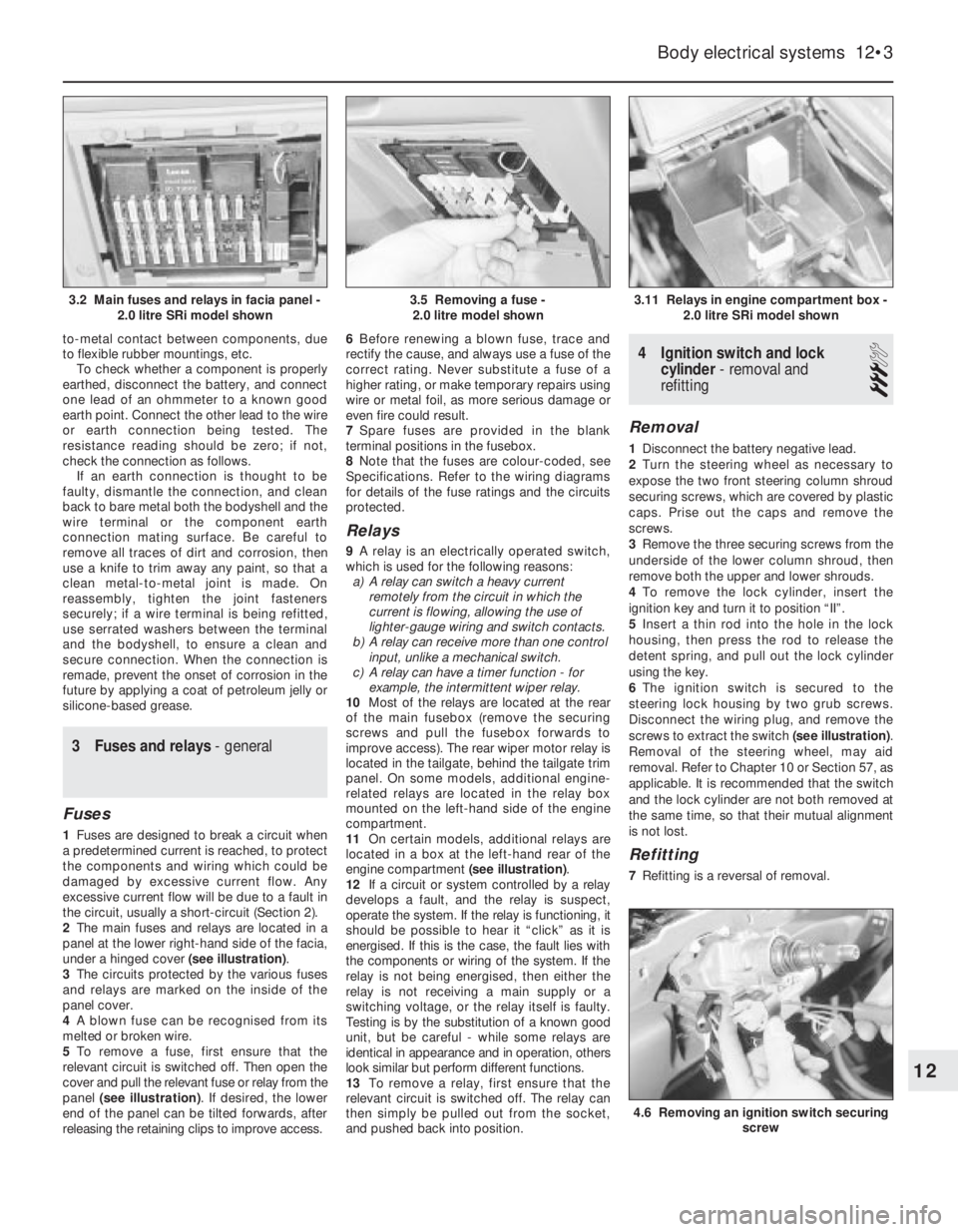
under a hinged cover (see illustration).
3The circuits protected by the various fuses
and relays are marked on the inside of the
panel cover.
4A blown fuse can be recognised from its
melted or broken wire.
5To remove a fuse, first ensure that the
relevant circuit is switched off. Then open the
cover and pull the relevant fuse or relay from the
panel (see illustration). If desired, the lower
end of the panel can be tilted forwards, after
releasing the retaining clips to improve access. 6Before renewing a blown fuse, trace and
rectify the cause, and always use a fuse of the
correct rating. Never substitute a fuse of a
higher rating, or make temporary repairs using
wire or metal foil, as more serious damage or
even fire could result.
7Spare fuses are provided in the blank
terminal positions in the fusebox.
8Note that the fuses are colour-coded, see
Specifications. Refer to the wiring diagrams
for details of the fuse ratings and the circuits
protected.
Relays
9A relay is an electrically operated switch,
which is used for the following reasons:
a)A relay can switch a heavy current
remotely from the circuit in which the
current is flowing, allowing the use of
lighter-gauge wiring and switch contacts.
b)A relay can receive more than one control
input, unlike a mechanical switch.
c)A relay can have a timer function - for
example, the intermittent wiper relay.
10Most of the relays are located at the rear
of the main fusebox (remove the securing
screws and pull the fusebox forwards to
improve access). The rear wiper motor relay is
located in the tailgate, behind the tailgate trim
panel. On some models, additional engine-
related relays are located in the relay box
mounted on the left-hand side of the engine
compartment.
11On certain models, additional relays are
located in a box at the left-hand rear of the
engine compartment (see illustration).
12If a circuit or system controlled by a relay
develops a fault, and the relay is suspect,
operate the system. If the relay is functioning, it
should be possible to hear it “click” as it is
energised. If this is the case, the fault lies with
the components or wiring of the system. If the
relay is not being energised, then either the
relay is not receiving a main supply or a
switching voltage, or the relay itself is faulty.
Testing is by the substitution of a known good
unit, but be careful - while some relays are
identical in appearance and in operation, others
look similar but perform different functions.
13To remove a relay, first ensure that the
relevant circuit is switched off. The relay can
then simply be pulled out from the socket,
and pushed back into position.
4Ignition switch and lock
cylinder - removal and
refitting
3
Removal
1Disconnect the battery negative lead.
2Turn the steering wheel as necessary to
expose the two front steering column shroud
securing screws, which are covered by plastic
caps. Prise out the caps and remove the
screws.
3Remove the three securing screws from the
underside of the lower column shroud, then
remove both the upper and lower shrouds.
4To remove the lock cylinder, insert the
ignition key and turn it to position “II”.
5Insert a thin rod into the hole in the lock
housing, then press the rod to release the
detent spring, and pull out the lock cylinder
using the key.
6The ignition switch is secured to the
steering lock housing by two grub screws.
Disconnect the wiring plug, and remove the
screws to extract the switch (see illustration).
Removal of the steering wheel, may aid
removal. Refer to Chapter 10 or Section 57, as
applicable. It is recommended that the switch
and the lock cylinder are not both removed at
the same time, so that their mutual alignment
is not lost.
Refitting
7Refitting is a reversal of removal.
Body electrical systems 12•3
3.11 Relays in engine compartment box -
2.0 litre SRi model shown
4.6 Removing an ignition switch securing
screw
3.5 Removing a fuse -
2.0 litre model shown3.2 Main fuses and relays in facia panel -
2.0 litre SRi model shown
12
Page 91 of 525
28The system also incorporates a separate
ignition amplifier module that transmits
amplified signals from the main system
module to trigger the HT pulse from the
ignition coil. The module is mounted on the
ignition coil’s bracket/baseplate.
29Additionally, the Motronic module
receives information from a cylinder
block-mounted knock sensor, which senses
“knocking” (or pre-ignition) just as it begins to
occur, enabling the module to retard the
ignition timing, thus preventing engine
damage.
Simtec 56.1
30This system uses increased amount of
electronic components instead of mechanical
parts as sensors and actuators with the
Simtec engine management system. This
provides more precise operating data as well
as greater problem free motoring.
31The control unit is equipped with
electronic ignition control. Called ‘Micropro-
cessor Spark Timing System, inductive
triggered’, (or MSTS-i), and means that the
mechanical high voltage distributor is no
longer needed. It is located behind the trim
panel, on the right-hand side footwell (door
pillar).
32The ignition coil is replaced by a dual
spark ignition coil, which is switched directly
by the output stages in the control unit.
33A camshaft sensor will maintain
emergency operation, should the crankshaft
inductive pulse pick-up, malfunction. These
sense TDC (‘Top Dead Centre’), crankshaft
angle and engine speed. The signals are used
by the control unit to calculate ignition point
and for fuel injection.
34The ‘hot film airflow meter’ determines the
mass of air taken in by the engine. The system
uses this information to calculate the correct
amount of fuel needed for injection in the
engine.
35The air inlet temperature sensor (NTC), is
fitted in the air inlet duct between the air
cleaner and the hot mass air flow meter.
36A controlled canister purge valve is
actuated by the system. The tank ventilation is
monitored closely with the Lambda control (or
oxygen sensor) and adaptation by the
computer within the control unit.
37A knock control system is also fitted. This
eliminates the need for octane number
adjustment, as it is performed automatically
through the control unit.
3Electrical system -
precautions
1It is necessary to take extra care when
working on the electrical system, to avoid
damage to semi-conductor devices (diodes
and transistors), and to avoid the risk of
personal injury. Along with the precautions
given in the “Safety first!” Section at the
beginning of this manual, take note of the
following points when working on the system.
2Always remove rings, watches, etc. before
working on the electrical system. Even with
the battery disconnected, discharge could
occur if a component live terminal is earthed
through a metal object. This could cause a
shock or nasty burn.
3Do not reverse the battery connections.
Components such as the alternator, or any
other component having semi-conductor
circuitry, could be irreparably damaged.
4If the engine is being started using jump
leads and a slave battery, connect the
batteries positive to positive and negative to
negative. This also applies when connecting a
battery charger.
5Never disconnect the battery terminals, or
alternator multi-plug connector, when the
engine is running.
6The battery leads and alternator wiring
must be disconnected before carrying out any
electric welding on the vehicle.
7Never use an ohmmeter of the type
incorporating a hand-cranked generator for
circuit or continuity testing.
8Engine management modules are very
sensitive components, and certain
precautions must be taken, to avoid damage
to the module when working on a vehicle
equipped with an engine management
system, as follows.
9When carrying out welding operations on
the vehicle using electric welding equipment,
the battery and alternator should be
disconnected.
10Although underbonnet-mounted modules
will tolerate normal underbonnet conditions,
they can be adversely affected by excess heat
or moisture. If using welding equipment or
pressure washing equipment near the
module, take care not to direct heat, or jets of
water or steam, at the module. If this cannot
be avoided, remove the module from the
vehicle, and protect its wiring plug with a
plastic bag.
11Before disconnecting any wiring, or
removing components, always ensure that the
ignition is switched off.
12Do not attempt to improvise fault
diagnosis procedures using a test lamp or
multimeter, as irreparable damage could be
caused to the module.13After working on ignition/engine
management system components, ensure
that all wiring is correctly reconnected before
reconnecting the battery or switching on the
ignition.
14Any ignition system that uses a
“Hall-effect” generator in the distributor,
cannot be tested. Test equipment that uses
its own power source (e.g. an ohmmeter),
when connected to the distributor or the
“Hall-effect” generator, will be damaged.
4Ignition system testing -
general
3
Note: Refer to Section 3 before proceeding.
Always switch off the ignition before
disconnecting or connecting any component
and when using a multi-meter to check
resistances. Any voltmeter or multi-meter
used to test ignition system components must
have an impedance of 10 meg ohms or
greater
1Electronic ignition system components are
normally very reliable. Most faults are far more
likely to be due to loose or dirty connections,
or to “tracking” of HT voltage due to dirt,
dampness or damaged insulation than to
component failure. Always check all wiring
thoroughly before condemning an electrical
component and work methodically to
eliminate all other possibilities before deciding
that a particular component is faulty.
2The old practice of checking for a spark by
holding the live end of a HT lead a short
distance away from the engine is not
recommended. Not only is there a high risk of
a powerful electric shock, but the ignition coil
or amplifier module will be damaged.
Similarly, never try to “diagnose” misfires by
pulling off one HT lead at a time. Note also
that the ECU is at risk if the system is
triggered with an open (i.e., not properly
earthed) HT circuit; ECU’s are very expensive
to replace, so take care!
3If you are in any doubt as to your skill and
ability to test an ignition system component or
if you do not have the required equipment,
take the vehicle to a suitably equipped
Vauxhall dealer. It is better to pay the labour
charges involved in having the vehicle
checked by an expert than to risk damage to
the system or to yourself.
4If the engine either will not turn over at all,
or only turns very slowly, check the battery
and starter motor. Connect a voltmeter across
the battery terminals (meter positive probe to
battery positive terminal) and disconnect the
ignition coil HT lead from the distributor cap
and earth. Note the voltage reading obtained
while turning over the engine on the starter for
(no more than) ten seconds. If the reading
obtained is less than approximately 9.5 volts,
check the battery, battery connections, starter
motor and charging system.
5•4Engine electrical systems
Warning: The HT voltage
generated by an electronic
ignition system is extremely
high and, in certain
circumstances, could prove fatal. Take
care to avoid receiving electric shocks
from the HT side of the ignition system.
Do not handle HT leads, or touch the
distributor or coil, when the engine is
running. If tracing faults in the HT circuit,
use well-insulated tools to manipulate live
leads
Page 116 of 525
4Certain models may have additional
underbody shields and splashguards fitted,
which may be attached to the wheel arch liners.
32Engine undershield (DOHC
models) - removal and
refitting
2
Removal
1Apply the handbrake, then jack up the front
of the vehicle, and support on axle stands
(see “Jacking and Vehicle Support”).
2Extract the two securing screws, and
remove the oil filter access panel.
3Working around the edges of the splash
shield, remove the self tapping screws that
secure the shield to the body, noting that
some of the screws also secure the wheel
arch liners.
4With the help of an assistant, pull the shield
from the vehicle, and place it to one side to
avoid damage.
Refitting
5Refitting is a reversal of removal.
33Fuel filler flap -removal and
refitting
2
Removal
1Open the flap for access to the four screws
securing the flap to the rear wing.2Remove the securing screws, and withdraw
the flap.
Refitting
3Refitting is a reversal of removal.
34Sunroof components -
removal and refitting
4
Note:The sunroof is a complex piece of
equipment consisting of a large number of
components. It is strongly recommended that
the sunroof mechanism is not disturbed unless
necessary. If the sunroof mechanism is faulty, or
requires overhaul, consult a dealer for advice.
Glass panel
Removal
1Push the sunshade fully rearwards, and
open the glass panel halfway.
2Extract the four securing screws from the
front edge of the guide rail plastic surround,
and withdraw the surround down through the
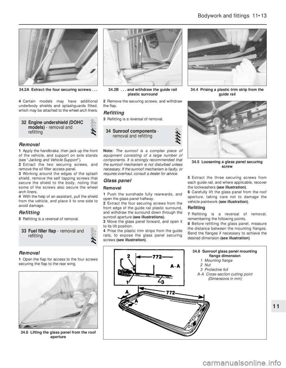
sunroof aperture (see illustrations).
3Move the glass panel forward, and open it
to its tilt position.
4Prise the plastic trim strips from the guide
rails, to expose the glass panel securing
screws (see illustration).5Extract the three securing screws from
each guide rail, and where applicable, recover
the lockwashers (see illustration).
6Carefully lift the glass panel from the roof
aperture, taking care not to damage the
vehicle paintwork (see illustration).
Refitting
7Refitting is a reversal of removal,
remembering the following points.
8Before refitting the glass panel, measure
the distance between the mounting flanges.
Bend the flanges if necessary to achieve the
desired dimension (see illustration).
Bodywork and fittings 11•13
34.4 Prising a plastic trim strip from the
guide rail
34.6 Lifting the glass panel from the roof
aperture
34.5 Loosening a glass panel securing
screw
34.2B . . . and withdraw the guide rail
plastic surround34.2A Extract the four securing screws . . .
11
34.8 Sunroof glass panel mounting
flange dimension
1 Mounting flange
2 Nut
3 Protective foil
A-A Cross-section cutting point
(Dimensions in mm)
Page 127 of 525
2Exhaust gas recirculation
(EGR) system - general
The system reintroduces small amounts of
exhaust gas into the combustion cycle to
reduce the generation of oxides of nitrogen
(NOx).
On C16 NZ, C16 NZ2 and C18 NZ engines,
the volume of exhaust gas reintroduced is
governed by manifold vacuum, through the
EGR valve mounted on the inlet manifold.
When the valve is opened small amounts of
exhaust gas are allowed to enter the inlet
tract, passing through ports in the cylinder
head.
On X16 SZ engines the EGR valve is
operated by an EGR module, mounted on the
left-hand side of the engine compartment
behind the battery. This module amplifies
signals received from the fuel system ECU
and operates the EGR valve electronically
providing precise control of exhaust gas
recirculation under all engine conditions.
3EGR valve (Multec system
models) - testing, removal and
refitting
2
Testing
1On C16 NZ, C16 NZ2 and C18 NZ engines,
it is recommended that the system is checked
annually, by checking the movement of the
valve’s diaphragm carrier plate as follows.
Note that the carrier plate is visible only
through the apertures in the underside of the
valve, so a battery-operated torch and small
mirror may be useful. On X16 SZ engines,
Vauxhall test equipment is necessary to check
the EGR system.
2With the engine fully warmed up to normal
operating temperature and idling, briefly open
and close the throttle. The carrier plate should
move upwards as the manifold vacuum
changes. When the engine is idling smoothly
again, press the carrier plate upwards (do this
very carefully, so that the plate is not distorted or
the diaphragm damaged). The idle speed should
drop significantly (approximately 100 rpm).
3If the valve does not respond as described,
it must be cleaned.
Removal
4Pull off the hose from the valve, then unbolt
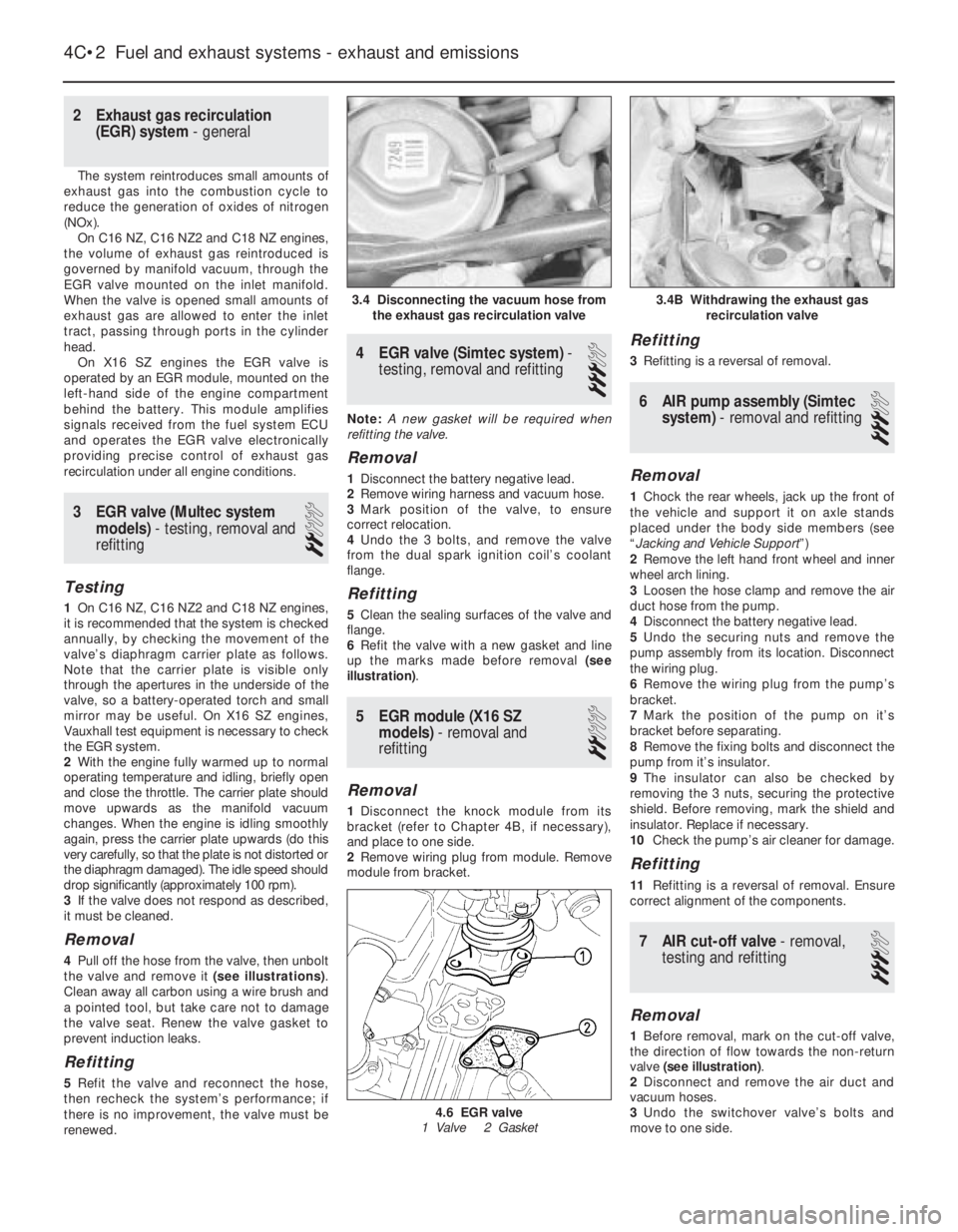
the valve and remove it (see illustrations).
Clean away all carbon using a wire brush and
a pointed tool, but take care not to damage
the valve seat. Renew the valve gasket to
prevent induction leaks.
Refitting
5Refit the valve and reconnect the hose,
then recheck the system’s performance; if
there is no improvement, the valve must be
renewed.
4EGR valve (Simtec system) -
testing, removal and refitting
3
Note: A new gasket will be required when
refitting the valve.
Removal
1Disconnect the battery negative lead.
2Remove wiring harness and vacuum hose.
3Mark position of the valve, to ensure
correct relocation.
4Undo the 3 bolts, and remove the valve
from the dual spark ignition coil’s coolant
flange.
Refitting
5Clean the sealing surfaces of the valve and
flange.
6Refit the valve with a new gasket and line
up the marks made before removal (see
illustration).
5EGR module (X16 SZ
models) - removal and
refitting
2
Removal
1Disconnect the knock module from its
bracket (refer to Chapter 4B, if necessary),
and place to one side.
2Remove wiring plug from module. Remove
module from bracket.
Refitting
3Refitting is a reversal of removal.
6AIR pump assembly (Simtec
system) - removal and refitting
3
Removal
1Chock the rear wheels, jack up the front of
the vehicle and support it on axle stands
placed under the body side members (see
“Jacking and Vehicle Support”)
2Remove the left hand front wheel and inner
wheel arch lining.
3Loosen the hose clamp and remove the air
duct hose from the pump.
4Disconnect the battery negative lead.
5Undo the securing nuts and remove the
pump assembly from its location. Disconnect
the wiring plug.
6Remove the wiring plug from the pump’s
bracket.
7Mark the position of the pump on it’s
bracket before separating.
8Remove the fixing bolts and disconnect the
pump from it’s insulator.
9The insulator can also be checked by
removing the 3 nuts, securing the protective
shield. Before removing, mark the shield and
insulator. Replace if necessary.
10Check the pump’s air cleaner for damage.
Refitting
11Refitting is a reversal of removal. Ensure
correct alignment of the components.
7AIR cut-off valve - removal,
testing and refitting
3
Removal
1Before removal, mark on the cut-off valve,
the direction of flow towards the non-return
valve (see illustration).
2Disconnect and remove the air duct and
vacuum hoses.
3Undo the switchover valve’s bolts and
move to one side.
4C•2Fuel and exhaust systems - exhaust and emissions
3.4 Disconnecting the vacuum hose from
the exhaust gas recirculation valve
4.6 EGR valve
1 Valve 2 Gasket
3.4B Withdrawing the exhaust gas
recirculation valve
Page 137 of 525
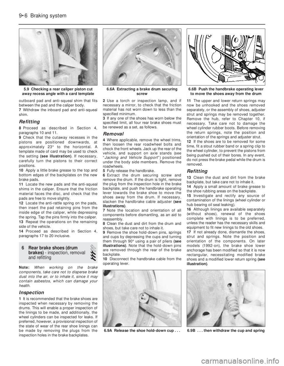
outboard pad and anti-squeal shim that fits
between the pad and the caliper body.
7Withdraw the inboard pad and anti-squeal
shim.
Refitting
8Proceed as described in Section 4,
paragraphs 10 and 11.
9Check that the cutaway recesses in the
pistons are positioned downwards, at
approximately 23°to the horizontal. A
template made of card may be used to check
the setting (see illustration). If necessary,
carefully turn the pistons to their correct
positions.
10Apply a little brake grease to the top and
bottom edges of the backplates on the new
brake pads.
11Locate the new pads and the anti-squeal
shims in the caliper. Ensure that the friction
material faces the disc, and check that the
pads are free to move slightly.
12Locate the anti-rattle spring on the pads,
then insert the pad retaining pins from the
inside edge of the caliper, while depressing
the spring. Tap the pins firmly into the caliper.
13Repeat the operations on the remaining
side of the vehicle.
14Proceed as described in Section 4,
paragraphs 17 to 20 inclusive.
6Rear brake shoes (drum
brakes) - inspection, removal
and refitting
3
Note: When working on the brake
components, take care not to disperse brake
dust into the air, or to inhale it, since it may
contain asbestos, which can damage your
health.
Inspection
1It is recommended that the brake shoes are
inspected when necessary by removing the
drums. This will enable a proper inspection of
the linings to be made, and additionally, the
wheel cylinders can be inspected for leaks. If
preferred, however, a provisional inspection of
the state of wear of the rear shoe linings can
be made by removing the plugs from the
inspection holes in the brake backplates.2Use a torch or inspection lamp, and if
necessary a mirror, to check that the friction
material has not worn down to less than the
specified minimum.
3If any one of the shoes has worn below the
specified limit, all four rear brake shoes must
be renewed as a set, as follows.
Removal
4Where applicable, remove the wheel trims,
then loosen the rear roadwheel bolts and
chock the front wheels. Jack up the rear of the
vehicle, and support on axle stands (see
“Jacking and Vehicle Support”) positioned
under the body side members. Remove the
roadwheels.
5Fully release the handbrake.
6Extract the drum securing screw and
remove the drum. If the drum is tight, remove
the plug from the inspection hole in the brake
backplate, and push the handbrake operating
lever towards the brake shoe to move the
shoes away from the drum. If necessary,
slacken the handbrake cable adjuster (see
illustrations).
7Note the location and orientation of all
components before dismantling, as an aid to
reassembly.
8Clean the dust and dirt from the drum and
shoes, but take care not to inhale it.
9Remove the shoe hold-down pins, springs
and cups by depressing the cups and turning
them through 90°using a pair of pliers (see
illustrations). Note that the hold-down pins
are removed through the rear of the brake
backplate.
10Disconnect the handbrake cable from the
operating lever.11The upper and lower return springs may
now be unhooked and the shoes removed
separately, or the assembly of shoes, adjuster
strut and springs may be removed together.
Remove the hub, refer to Chapter 10, if
necessary. Take care not to damage the
wheel cylinder rubber boots. Before removing
the return springs, note the position and
orientation of the springs and adjuster strut.
12If the shoes are to be removed for some
time, fit a stout rubber band or a spring clip to
the wheel cylinder, to prevent the pistons from
being pushed out of their bores. In any event,
do not press the brake pedal while the drum is
removed.
Refitting
13Clean the dust and dirt from the brake
backplate, but take care not to inhale it.
14Apply a small amount of brake grease to
the shoe rubbing areas on the backplate.
15Investigate and rectify any source of
contamination of the linings (wheel cylinder or
hub bearing oil seal leaking).
16Although linings are available separately
(without shoes), renewal of the shoes
complete with linings is to be preferred,
unless the reader has the necessary skills and
equipment to fit new linings to the old shoes.
17If not already done, dismantle the shoes,
strut and springs. Note the position and
orientation of the components. On later
models (1992-on), the brake shoe lower
anchorage has been modified so that it is now
rectangular, necessitating modified brake
shoes and a modified lower return spring (see
illustration).
9•6Braking system
5.9 Checking a rear caliper piston cut
away recess angle with a card template6.6B Push the handbrake operating lever
to move the shoes away from the drum
6.9B . . . then withdraw the cup and spring6.9A Release the shoe hold-down cup . . .
6.6A Extracting a brake drum securing
screw
Page 142 of 525
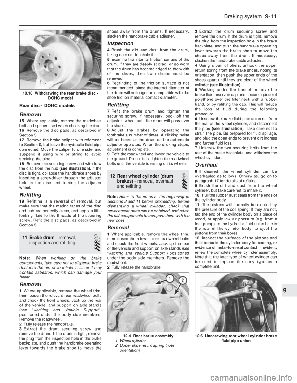
Rear disc - DOHC models
Removal
15Where applicable, remove the roadwheel
bolt and spacer used when checking the disc.
16Remove the disc pads, as described in
Section 5.
17Remove the brake caliper with reference
to Section 9, but leave the hydraulic fluid pipe
connected. Move the caliper to one side, and
suspend it using wire or string to avoid
straining the pipe.
18Remove the securing screw and withdraw
the disc from the hub (see illustration). If the
disc is tight, collapse the handbrake shoes by
inserting a screwdriver through the adjuster
hole in the disc and turning the adjuster
wheel.
Refitting
19Refitting is a reversal of removal, but
make sure that the mating faces of the disc
and hub are perfectly clean, and apply a little
locking fluid to the threads of the securing
screw. Refit the disc pads, as described in
Section 5.
11Brake drum - removal,
inspection and refitting
3
Note: When working on the brake
components, take care not to disperse brake
dust into the air, or to inhale it, since it may
contain asbestos, which can damage your
health.
Removal
1Where applicable, remove the wheel trim,
then loosen the relevant rear roadwheel bolts
and chock the front wheels. Jack up the rear
of the vehicle, and support on axle stands
(see “Jacking and Vehicle Support”)
positioned under the body side members.
Remove the roadwheel.
2Fully release the handbrake.
3Extract the drum securing screw and
remove the drum. If the drum is tight, remove
the plug from the inspection hole in the brake
backplate, and push the handbrake operating
lever towards the brake shoe to move theshoes away from the drums. If necessary,
slacken the handbrake cable adjuster.
Inspection
4Brush the dirt and dust from the drum,
taking care not to inhale it.
5Examine the internal friction surface of the
drum. If they are deeply scored, or so worn
that the drum has become ridged to the width
of the shoes, then both drums must be
renewed.
6Regrinding of the friction surface is not
recommended, since the internal diameter of
the drum will no longer be compatible with the
shoe friction material contact diameter.
Refitting
7Refit the brake drum and tighten the
securing screw. If necessary, back off the
adjuster wheel until the drum will pass over
the shoes.
8Adjust the brakes by operating the
footbrake a number of times. A clicking noise
will be heard at the drum as the automatic
adjuster operates. When the clicking stops,
adjustment is complete.
9Refit the roadwheel and lower the vehicle to
the ground. Do not fully tighten the roadwheel
bolts until the vehicle is resting on its wheels.
12Rear wheel cylinder (drum
brakes) - removal, overhaul
and refitting
3
Note: Refer to the notes at the beginning of
Sections 3 and 11 before proceeding. Before
dismantling a wheel cylinder, check that
replacement parts can be obtained, and retain
the old components to compare them with the
new ones
Removal
1Where applicable, remove the wheel trim,
then loosen the relevant rear roadwheel bolts
and chock the front wheels. Jack up the rear
of the vehicle and support on axle stands (see
“Jacking and Vehicle Support”) positioned
under the body side members. Remove the
roadwheel.
2Fully release the handbrake.3Extract the drum securing screw and
remove the drum. If the drum is tight, remove
the plug from the inspection hole in the brake
backplate, and push the handbrake operating
lever towards the brake shoe to move the
shoes away from the drum. If necessary,
slacken the handbrake cable adjuster.
4Using a pair of pliers, unhook the upper
return spring from the brake shoes, noting its
orientation, then push the upper ends of the
shoes apart until they are clear of the wheel
cylinder (see illustration).
5Working under the bonnet, remove the
brake fluid reservoir cap and secure a piece of
polythene over the filler neck with a rubber
band, or by refitting the cap. This will reduce
the loss of fluid during the following
procedure.
6Unscrew the brake fluid pipe union nut from
the rear of the wheel cylinder, and disconnect
the pipe (see illustration). Take care not to
strain the pipe. Be prepared for fluid spillage,
and plug the open ends to prevent dirt ingress
and further fluid loss.
7Unscrew the two securing bolts from the
rear of the brake backplate, and withdraw the
wheel cylinder.
Overhaul
8If desired, the wheel cylinder can be
overhauled as follows. Otherwise, go on to
paragraph 17 for details of refitting.
9Brush the dirt and dust from the wheel
cylinder, but take care not to inhale it.
10Pull the rubber dust seals from the ends of
the cylinder body.
11The pistons will normally be ejected by
the pressure of the coil spring. If they are not,
tap the end of the cylinder body on a piece of
wood, or apply low air pressure (e.g. from a
foot pump), to the hydraulic fluid union hole in
the rear of the cylinder body, to eject the
pistons from their bores.
12Inspect the surfaces of the pistons and
their bores in the cylinder body for scoring, or
evidence of metal-to-metal contact. If evident,
renew the complete wheel cylinder assembly.
Note that the later type of wheel cylinder can
be used to replace the early type as a
complete unit.
Braking system 9•11
12.6 Unscrewing rear wheel cylinder brake
fluid pipe union12.4 Rear brake assembly
1 Wheel cylinder
2 Upper shoe return spring (note
orientation)
10.18 Withdrawing the rear brake disc -
DOHC model
9
Page 174 of 525
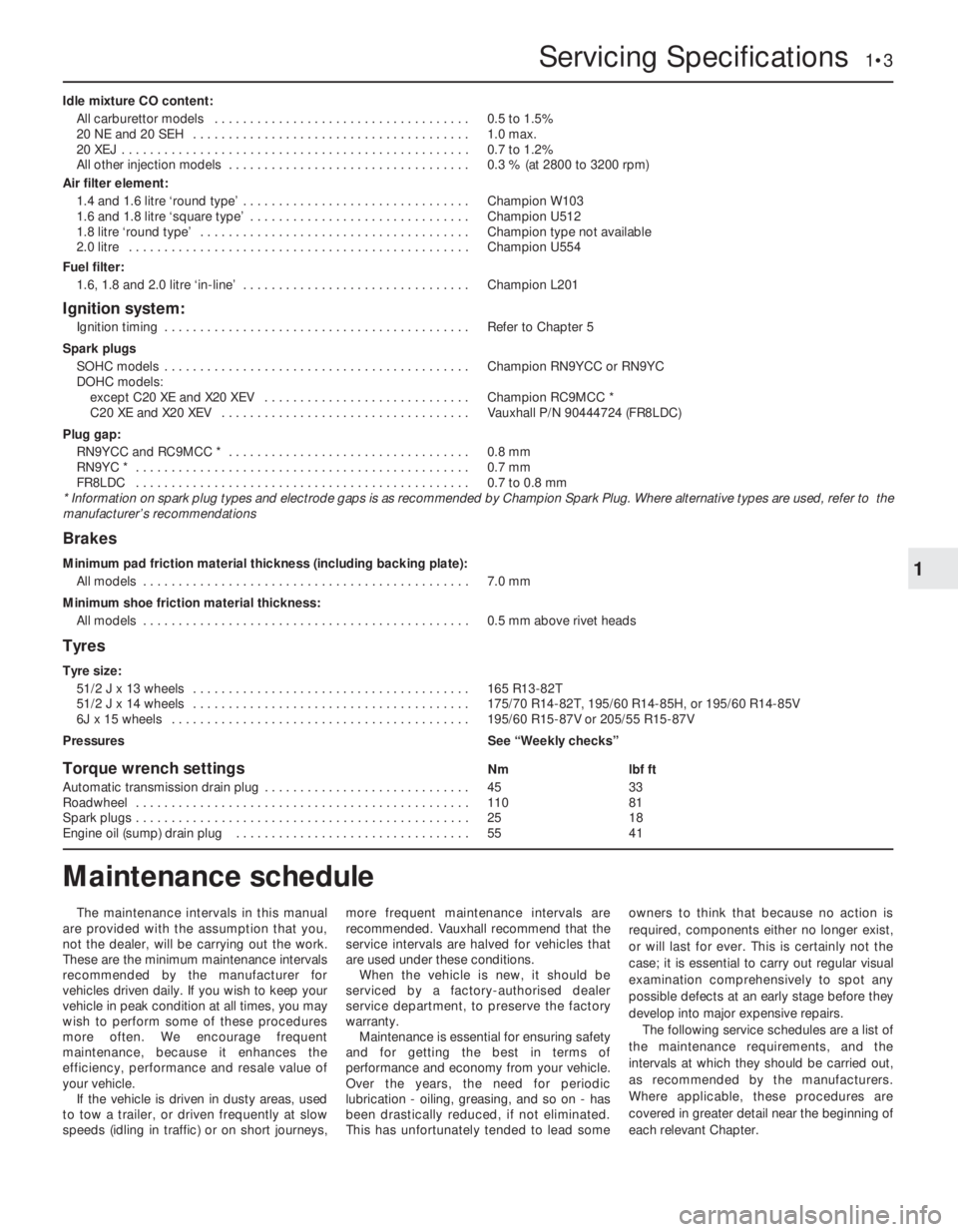
Idle mixture CO content:
All carburettor models . . . . . . . . . . . . . . . . . . . . . . . . . . . . . . . . . . . .0.5 to 1.5%
20 NE and 20 SEH . . . . . . . . . . . . . . . . . . . . . . . . . . . . . . . . . . . . . . .1.0 max.
20 XEJ . . . . . . . . . . . . . . . . . . . . . . . . . . . . . . . . . . . . . . . . . . . . . . . . .0.7 to 1.2%
All other injection models . . . . . . . . . . . . . . . . . . . . . . . . . . . . . . . . . .0.3 % (at 2800 to 3200 rpm)
Air filter element:
1.4 and 1.6 litre ‘round type’ . . . . . . . . . . . . . . . . . . . . . . . . . . . . . . . .Champion W103
1.6 and 1.8 litre ‘square type’ . . . . . . . . . . . . . . . . . . . . . . . . . . . . . . .Champion U512
1.8 litre ‘round type’ . . . . . . . . . . . . . . . . . . . . . . . . . . . . . . . . . . . . . .Champion type not available
2.0 litre . . . . . . . . . . . . . . . . . . . . . . . . . . . . . . . . . . . . . . . . . . . . . . . .Champion U554
Fuel filter:
1.6, 1.8 and 2.0 litre ‘in-line’ . . . . . . . . . . . . . . . . . . . . . . . . . . . . . . . .Champion L201
Ignition system:
Ignition timing . . . . . . . . . . . . . . . . . . . . . . . . . . . . . . . . . . . . . . . . . . .Refer to Chapter 5
Spark plugs
SOHC models . . . . . . . . . . . . . . . . . . . . . . . . . . . . . . . . . . . . . . . . . . .Champion RN9YCC or RN9YC
DOHC models:
except C20 XE and X20 XEV . . . . . . . . . . . . . . . . . . . . . . . . . . . . .Champion RC9MCC *
C20 XE and X20 XEV . . . . . . . . . . . . . . . . . . . . . . . . . . . . . . . . . . .Vauxhall P/N 90444724 (FR8LDC)
Plug gap:
RN9YCC and RC9MCC * . . . . . . . . . . . . . . . . . . . . . . . . . . . . . . . . . .0.8 mm
RN9YC * . . . . . . . . . . . . . . . . . . . . . . . . . . . . . . . . . . . . . . . . . . . . . . .0.7 mm
FR8LDC . . . . . . . . . . . . . . . . . . . . . . . . . . . . . . . . . . . . . . . . . . . . . . .0.7 to 0.8 mm
* Information on spark plug types and electrode gaps is as recommended by Champion Spark Plug. Where alternative types are used, refer to the
manufacturer’s recommendations
Brakes
Minimum pad friction material thickness (including backing plate):
All models . . . . . . . . . . . . . . . . . . . . . . . . . . . . . . . . . . . . . . . . . . . . . .7.0 mm
Minimum shoe friction material thickness:
All models . . . . . . . . . . . . . . . . . . . . . . . . . . . . . . . . . . . . . . . . . . . . . .0.5 mm above rivet heads
Tyres
Tyre size:
51/2 J x 13 wheels . . . . . . . . . . . . . . . . . . . . . . . . . . . . . . . . . . . . . . .165 R13-82T
51/2 J x 14 wheels . . . . . . . . . . . . . . . . . . . . . . . . . . . . . . . . . . . . . . .175/70 R14-82T, 195/60 R14-85H, or 195/60 R14-85V
6J x 15 wheels . . . . . . . . . . . . . . . . . . . . . . . . . . . . . . . . . . . . . . . . . .195/60 R15-87V or 205/55 R15-87V
PressuresSee “Weekly checks”
Torque wrench settingsNmlbf ft
Automatic transmission drain plug . . . . . . . . . . . . . . . . . . . . . . . . . . . . .4533
Roadwheel . . . . . . . . . . . . . . . . . . . . . . . . . . . . . . . . . . . . . . . . . . . . . . .11081
Spark plugs . . . . . . . . . . . . . . . . . . . . . . . . . . . . . . . . . . . . . . . . . . . . . . .2518
Engine oil (sump) drain plug . . . . . . . . . . . . . . . . . . . . . . . . . . . . . . . . .5541
Servicing Specifications 1•3
1
The maintenance intervals in this manual
are provided with the assumption that you,
not the dealer, will be carrying out the work.
These are the minimum maintenance intervals
recommended by the manufacturer for
vehicles driven daily. If you wish to keep your
vehicle in peak condition at all times, you may
wish to perform some of these procedures
more often. We encourage frequent
maintenance, because it enhances the
efficiency, performance and resale value of
your vehicle.
If the vehicle is driven in dusty areas, used
to tow a trailer, or driven frequently at slow
speeds (idling in traffic) or on short journeys,more frequent maintenance intervals are
recommended. Vauxhall recommend that the
service intervals are halved for vehicles that
are used under these conditions.
When the vehicle is new, it should be
serviced by a factory-authorised dealer
service department, to preserve the factory
warranty.
Maintenance is essential for ensuring safety
and for getting the best in terms of
performance and economy from your vehicle.
Over the years, the need for periodic
lubrication -oiling, greasing, and so on -has
been drastically reduced, if not eliminated.
This has unfortunately tended to lead someowners to think that because no action is
required, components either no longer exist,
or will last for ever. This is certainly not the
case; it is essential to carry out regular visual
examination comprehensively to spot any
possible defects at an early stage before they
develop into major expensive repairs.
The following service schedules are a list of
the maintenance requirements, and the
intervals at which they should be carried out,
as recommended by the manufacturers.
Where applicable, these procedures are
covered in greater detail near the beginning of
each relevant Chapter.
Maintenance schedule
Page 205 of 525
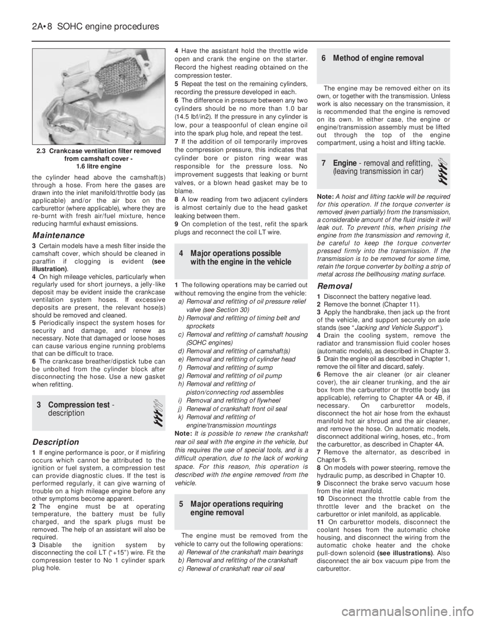
the cylinder head above the camshaft(s)
through a hose. From here the gases are
drawn into the inlet manifold/throttle body (as
applicable) and/or the air box on the
carburettor (where applicable), where they are
re-burnt with fresh air/fuel mixture, hence
reducing harmful exhaust emissions.
Maintenance
3Certain models have a mesh filter inside the
camshaft cover, which should be cleaned in
paraffin if clogging is evident (see
illustration).
4On high mileage vehicles, particularly when
regularly used for short journeys, a jelly-like
deposit may be evident inside the crankcase
ventilation system hoses. If excessive
deposits are present, the relevant hose(s)
should be removed and cleaned.
5Periodically inspect the system hoses for
security and damage, and renew as
necessary. Note that damaged or loose hoses
can cause various engine running problems
that can be difficult to trace.
6The crankcase breather/dipstick tube can
be unbolted from the cylinder block after
disconnecting the hose. Use a new gasket
when refitting.
3Compression test -
description
3
Description
1If engine performance is poor, or if misfiring
occurs which cannot be attributed to the
ignition or fuel system, a compression test
can provide diagnostic clues. If the test is
performed regularly, it can give warning of
trouble on a high mileage engine before any
other symptoms become apparent.
2The engine must be at operating
temperature, the battery must be fully
charged, and the spark plugs must be
removed. The help of an assistant will also be
required.
3Disable the ignition system by
disconnecting the coil LT (“+15”) wire. Fit the
compression tester to No 1 cylinder spark
plug hole.4Have the assistant hold the throttle wide
open and crank the engine on the starter.
Record the highest reading obtained on the
compression tester.
5Repeat the test on the remaining cylinders,
recording the pressure developed in each.
6The difference in pressure between any two
cylinders should be no more than 1.0 bar
(14.5 lbf/in2). If the pressure in any cylinder is
low, pour a teaspoonful of clean engine oil
into the spark plug hole, and repeat the test.
7If the addition of oil temporarily improves
the compression pressure, this indicates that
cylinder bore or piston ring wear was
responsible for the pressure loss. No
improvement suggests that leaking or burnt
valves, or a blown head gasket may be to
blame.
8A low reading from two adjacent cylinders
is almost certainly due to the head gasket
leaking between them.
9On completion of the test, refit the spark
plugs and reconnect the coil LT wire.
4Major operations possible
with the engine in the vehicle
1The following operations may be carried out
without removing the engine from the vehicle:
a)Removal and refitting of oil pressure relief
valve (see Section 30)
b)Removal and refitting of timing belt and
sprockets
c)Removal and refitting of camshaft housing
(SOHC engines)
d)Removal and refitting of camshaft(s)
e)Removal and refitting of cylinder head
f)Removal and refitting of sump
g)Removal and refitting of oil pump
h)Removal and refitting of
piston/connecting rod assemblies
i)Removal and refitting of flywheel
j)Renewal of crankshaft front oil seal
k)Removal and refitting of
engine/transmission mountings
Note: It is possible to renew the crankshaft
rear oil seal with the engine in the vehicle, but
this requires the use of special tools, and is a
difficult operation, due to the lack of working
space. For this reason, this operation is
described with the engine removed from the
vehicle.
5Major operations requiring
engine removal
The engine must be removed from the
vehicle to carry out the following operations:
a)Renewal of the crankshaft main bearings
b)Removal and refitting of the crankshaft
c)Renewal of crankshaft rear oil seal
6Method of engine removal
The engine may be removed either on its
own, or together with the transmission. Unless
work is also necessary on the transmission, it
is recommended that the engine is removed
on its own. In either case, the engine or
engine/transmission assembly must be lifted
out through the top of the engine
compartment, using a hoist and lifting tackle.
7Engine - removal and refitting,
(leaving transmission in car)
4
Note: A hoist and lifting tackle will be required
for this operation.If the torque converter is
removed (even partially) from the transmission,
a considerable amount of the fluid inside it will
leak out. To prevent this, when prising the
engine from the transmission and removing it,
be careful to keep the torque converter
pressed firmly into the transmission. If the
transmission is to be removed for some time,
retain the torque converter by bolting a strip of
metal across the bellhousing mating surface.
Removal
1Disconnect the battery negative lead.
2Remove the bonnet (Chapter 11).
3Apply the handbrake, then jack up the front
of the vehicle, and support securely on axle
stands (see “Jacking and Vehicle Support”).
4Drain the cooling system, remove the
radiator and transmission fluid cooler hoses
(automatic models), as described in Chapter 3.
5Drain the engine oil as described in Chapter 1,
remove the oil filter and discard, safely.
6Remove the air cleaner (or air cleaner
cover), the air cleaner trunking, and the air
box from the carburettor or throttle body (as
applicable), referring to Chapter 4A or 4B, if
necessary. On carburettor models,
disconnect the hot air hose from the exhaust
manifold hot air shroud and the air cleaner,
and remove the hose. On automatic models,
disconnect additional wiring, hoses, etc., from
the carburettor, as described in Chapter 4A.
7Remove the alternator, as described in
Chapter 5.
8On models with power steering, remove the
hydraulic pump, as described in Chapter 10.
9Disconnect the brake servo vacuum hose
from the inlet manifold.
10Disconnect the throttle cable from the
throttle lever and the bracket on the
carburettor or inlet manifold, as applicable.
11On carburettor models, disconnect the
coolant hoses from the automatic choke
housing, and disconnect the wiring from the
automatic choke heater and the choke
pull-down solenoid (see illustrations). Also
disconnect the air box vacuum pipe from the
carburettor.
2A•8SOHC engine procedures
2.3 Crankcase ventilation filter removed
from camshaft cover -
1.6 litre engine