1988 OPEL CALIBRA coolant
[x] Cancel search: coolantPage 233 of 525
1General description
Engine cooling is achieved by a
conventional pump-assisted system, in which
the coolant is pressurised. The system
consists of a radiator, a coolant pump driven
by the engine timing belt, an electric cooling
fan, a thermostat, an expansion tank, and
connecting hoses. Hoses also carry coolant to
and from the heater matrix, which provides
heat for the ventilation and heating system.
The system works in the following way.
Cold coolant from one side of the radiator,
which is mounted at the front of the engine
compartment, passes to the coolant pump,
which forces the coolant through the coolant
passages in the cylinder block and cylinder
head. The coolant absorbs heat from the
engine, and then returns to the radiator
through the heater matrix. As the coolant
flows across the radiator it is cooled, and the
cycle is repeated.
Air flows through the radiator, to cool the
coolant as a result of the vehicle’s forward
motion. However, if the coolant temperature
exceeds a given figure, a
temperature-sensitive switch in the radiator
switches on the electric fan, to increase the
airflow through the radiator. The fan only
operates when necessary, with a consequent
reduction in noise and energy consumption.
To reduce the time taken for the engine to
warm up when starting from cold, the
thermostat, located in the cylinder head
outlet, prevents coolant flowing to the radiator
until the temperature has risen sufficiently.
Instead, the outflow from the cylinder head
bypasses the radiator, and is redirected
around the engine. When the temperature
reaches a given figure, the thermostat opens,
to allow coolant to flow to the radiator. The
thermostat is operated by the expansion of a
temperature sensitive wax capsule.
An expansion tank is incorporated in the
system, to allow for coolant expansion. The
system is topped up through a filler cap on
the expansion tank.
Note that later models may be fitted with
self-tensioning spring clamps to secure the
cooling system (including heater) hoses.
These clamps can be released by squeezing
together their free ends using a large pair of
self-grip pliers or similar so that the clamp can
be moved up the hose, clear of the union.
Check that the clamp is securely seated, and
check for leaks on reassembly.
2Cooling system -draining
2
1With the vehicle parked on level ground,
remove the expansion tank filler cap. If the
engine is warm, cover the filler cap with a
thick cloth, and unscrew the cap slowly, to
gradually relieve the system pressure. Take
care to avoid scalding by steam or coolant
escaping from the pressurised system.
2On DOHC models, remove the engine
undershield, with reference to Chapter 11.
3Position a container beneath the radiator
bottom hose connection, then slacken the
hose clip and ease the hose from the radiator
stub. If the hose joint has not been disturbed
for some time, it will be necessary to
manipulate the hose to break the joint. Allow
the coolant to drain into the container.
4As no cylinder block drain plug is fitted, and
the radiator bottom hose may be situated
halfway up the radiator, the system cannot be
drained completely. Care should therefore be
taken when refilling the system to maintain
antifreeze strength.
5If the coolant has been drained for a reason
other than renewal, then provided it is clean
and less than two years old, it can be re-used.
6If the coolant has been drained for renewal,
and is badly contaminated, the coolant
system should be flushed as described in
Section 4. As the system cannot be drained
completely, it is advisable to flush the system
whenever the coolant is renewed, to minimise
the impurities remaining in the system.
3Cooling system -flushing
2
1If coolant renewal has been neglected, or if
the antifreeze mixture has become diluted,
then in time the cooling system will gradually
lose efficiency, as the coolant passages
become restricted due to rust, scale deposits
and other sediment. To restore coolant
system efficiency, it is necessary to flush the
system clean.
2The radiator should be flushed
independently of the engine, to avoid
unnecessary contamination.
3To flush the radiator, disconnect the top
hose at the radiator, then insert a garden hose
into the radiator top inlet. Direct a flow of
clean water through the radiator, and continue
flushing until clean water emerges from the
radiator bottom outlet (the bottom hose
should have been disconnected to drain the
system). If after a reasonable period, the water
still does not run clear, the radiator can be
flushed with a good proprietary cleaning
agent. It is important that the manufacturer’s
instructions are followed carefully. If the
contamination is particularly bad, insert the
hose in the radiator bottom outlet, and flush
the radiator in reverse.
4To flush the engine, continue as follows.
1.4 and 1.6 litre models (except
C16 NZ2)
5Remove the thermostat as described in
Section 9, then temporarily refit the
thermostat cover.
6With the radiator top and bottom hoses
disconnected from the radiator, insert a
garden hose into the radiator bottom hose.
Direct a flow of clean water through the
engine, and continue flushing until clean water
emerges from the radiator top hose.
7On completion of flushing, refit the
thermostat, and reconnect the hoses.
C16 NZ2, 1.8 and 2.0 litre
models
8Remove the thermostat and cover
assembly, as described in Section 9.
9With the radiator bottom hose
disconnected from the radiator, insert a
garden hose into the radiator bottom hose.
Direct a flow of clean water through the
engine, and continue flushing until clean water
emerges from the thermostat housing. It is
advisable to place a sheet of plastic under the
thermostat housing to deflect water away
from the engine and surrounding components
during the flushing process.
10On completion of flushing, refit the
thermostat and cover assembly, reconnect
the hoses and remove the sheet of plastic.
4Cooling system -filling
2
1Before attempting to fill the cooling system,
make sure that all hoses and clips are in good
condition, and that the clips are tight. Note
that an antifreeze mixture must be used all
year round, to prevent corrosion of the alloy
engine components -refer to Section 5.
2On 1.4 and 1.6 litre models (except C16
NZ2), disconnect the wire and unscrew the
coolant temperature sender from the inlet
manifold.
3Remove the expansion tank cap, and fill the
system by slowly pouring the coolant into the
expansion tank to prevent air locks from
forming.
4If the coolant is being renewed, begin by
pouring in a couple of pints of water, followed
by the correct quantity of antifreeze (see
Section 5), then top-up with more water.
5On 1.4 and 1.6 litre models (except C16
NZ2), refit the coolant temperature sender
when coolant free of air bubbles emerges
from the orifice in the inlet manifold.
6Top-up the coolant level to the “COLD” (or
“KALT”) mark on the expansion tank, then refit
the expansion tank cap.
7Start the engine and run it until it reaches
normal operating temperature, then stop the
engine and allow it to cool.
8Check for leaks, particularly around
disturbed components. Check the coolant
3•2Cooling, heating and ventilation systems
When renewing any hoses,
use a little soapy water as a
lubricant, or soften the hose
in hot water. Do not use oil or
grease, as this may attack the rubber.
Page 234 of 525
level in the expansion tank, and top-up if
necessary. Note that the system must be cold
before an accurate level is indicated in the
expansion tank. If the expansion tank cap is
removed while the engine is still warm, cover
the cap with a thick cloth and unscrew the
cap slowly, to gradually relieve the system
pressure. Take care to avoid scalding by
steam or coolant escaping from the
pressurised system.
9On DOHC models, refit the engine
undershield on completion.
5Coolant mixture -general
1It is important to use an antifreeze mixture
in the cooling system all year round, to
prevent corrosion of the alloy engine
components. The coolant mixture should be
made up from clean, preferably soft, tap
water, and a good quality antifreeze
containing corrosion inhibitor. Ensure that the
antifreeze is ethylene glycol based, as the
cheaper methanol based types evaporate
over a period of time.
2The proportions of water and antifreeze
used will depend on the degree of protection
required. A coolant mixture containing 25%
antifreeze should be regarded as the
minimum strength required to maintain good
anti-corrosion properties. Details of the
degree of protection provided against freezing
will be supplied with the antifreeze by the
manufacturers. For absolute protection, use a
50% antifreeze mixture.
3The coolant mixture should be renewed
every two years, as the corrosion inhibitors
will deteriorate with time.
4Before filling the system with fresh coolant,
drain and flush the system, as described in
Sections 2 and 3, and check that all hoses are
secure and that the clips are tight. Antifreeze
has a searching action, and will leak morerapidly than plain water.
5Refill the system as described in Section 4.
All future topping-up should be carried out
using a coolant mixture of the same
proportions as that used to initially fill the
system.
6Do not use antifreeze in the windscreen
wash system, as it will attack the vehicle
paintwork. Note that antifreeze is poisonous,
and must be handled with due care.
6Radiator (manual
transmission) -removal and
refitting
3
Removal
1The radiator can be removed complete with
the coolant fan and shroud if there is no need
to disturb the fan. If desired, the fan and its
shroud can be removed from the radiator,
with reference to Section 12.
2Drain the cooling system, as described in
Section 2.
3Disconnect the radiator top hose and the
expansion tank at the radiator.
4Disconnect the battery negative lead, then
disconnect the wiring from the cooling fan
switch, located at the bottom right-hand side
of the radiator.5Disconnect the cooling fan wiring
connector, noting its location for use when
refitting.
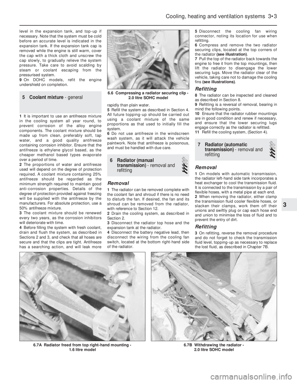
6Compress and remove the two radiator
securing clips, located at the top corners of
the radiator (see illustration).
7Pull the top of the radiator back towards the
engine to free it from the top mountings, then
lift the radiator to disengage the lower
securing lugs. Move the radiator clear of the
vehicle, taking care not to damage the cooling
fins (see illustrations).
Refitting
8The radiator can be inspected and cleaned
as described in Section 8.
9Refitting is a reversal of removal, bearing in
mind the following points.
10Ensure that the radiator rubber mountings
are in good condition and renew if necessary,
and ensure that the lower securing lugs
engage correctly as the radiator is refitted.
11Refill the cooling system, (Section 4).
7Radiator (automatic
transmission) -removal and
refitting
3
Removal
1On models with automatic transmission,
the radiator left-hand side tank incorporates a
heat exchanger to cool the transmission fluid.
It is connected to the transmission by a pair of
flexible hoses, with a metal pipe at each end.
2When removing the radiator, either clamp
the transmission fluid cooler flexible hoses, or
slacken their clamps, work them off their
unions and swiftly plug or cap each hose end
and union to minimise the loss of fluid and to
prevent the entry of dirt.
Refitting
3On refitting, reverse the removal procedure
and do not forget to check the transmission
fluid level, topping-up as necessary to replace
the lost fluid, as described in Chapter 7B.
Cooling, heating and ventilation systems 3•3
6.7B Withdrawing the radiator -
2.0 litre SOHC model6.7A Radiator freed from top right-hand mounting -
1.6 litre model
6.6 Compressing a radiator securing clip -
2.0 litre SOHC model
3
Page 235 of 525
8Radiator -inspection and
cleaning
2
1If the radiator has been removed due to
suspected blockage, reverse-flush it as
described in Section 3.
2Clean dirt and debris from the radiator fins,
using an air jet or a soft brush. Take care, as
the fins are easily damaged and are sharp.
3If necessary, a radiator specialist can
perform a “flow test” on the radiator, to
establish whether an internal blockage exists.
4A leaking radiator must be referred to a
specialist for permanent repair. Do not
attempt to weld or solder a leaking radiator,
as damage to the plastic components may
result.
5In an emergency, minor leaks from the
radiator can be cured by using a radiator
sealant.
9Thermostat - removal and
refitting
3
Note: A new O-ring should be used when
refitting the thermostat
1.4 and 1.6 litre models (except
C16 NZ2)
Removal
1Partially drain the cooling system, as
described in Section 2.
2Remove the timing belt and the camshaft
sprocket, as described in Chapters 2A or 2B,
(as applicable).
3Unscrew and remove the two upper bolts
securing the rear timing belt cover to the
cylinder head, and the lower right-hand bolt
securing the cover to the cylinder block.
4Disconnect the coolant hose from the
thermostat housing.
5Pull the rear timing belt cover forwards,
away from the cylinder head, for access to the
two thermostat housing securing bolts.
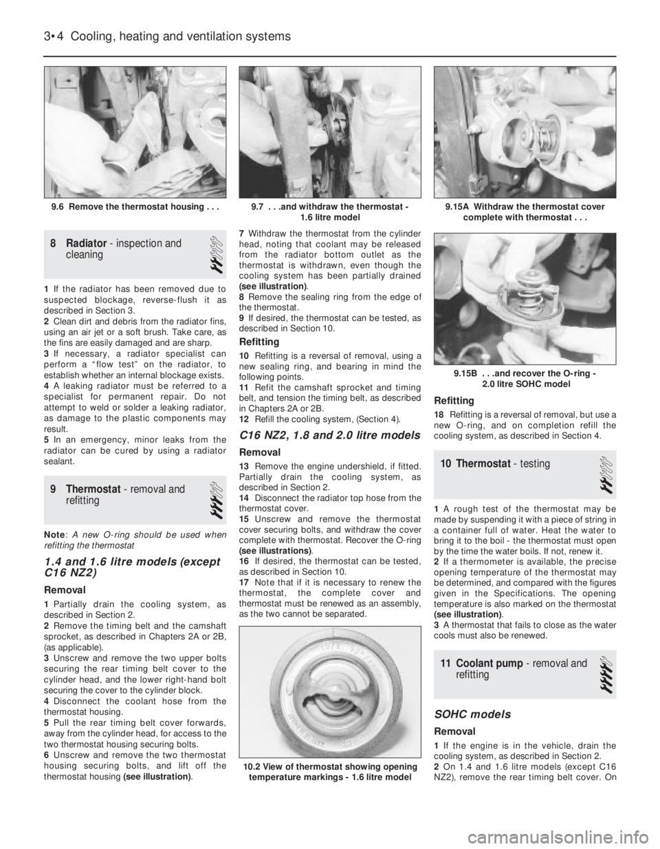
6Unscrew and remove the two thermostat
housing securing bolts, and lift off the
thermostat housing (see illustration).7Withdraw the thermostat from the cylinder
head, noting that coolant may be released
from the radiator bottom outlet as the
thermostat is withdrawn, even though the
cooling system has been partially drained
(see illustration).
8Remove the sealing ring from the edge of
the thermostat.
9If desired, the thermostat can be tested, as
described in Section 10.
Refitting
10Refitting is a reversal of removal, using a
new sealing ring, and bearing in mind the
following points.
11Refit the camshaft sprocket and timing
belt, and tension the timing belt, as described
in Chapters 2A or 2B.
12Refill the cooling system, (Section 4).
C16 NZ2, 1.8 and 2.0 litre models
Removal
13Remove the engine undershield, if fitted.
Partially drain the cooling system, as
described in Section 2.
14Disconnect the radiator top hose from the
thermostat cover.
15Unscrew and remove the thermostat
cover securing bolts, and withdraw the cover
complete with thermostat. Recover the O-ring
(see illustrations).
16If desired, the thermostat can be tested,
as described in Section 10.
17Note that if it is necessary to renew the
thermostat, the complete cover and
thermostat must be renewed as an assembly,
as the two cannot be separated.
Refitting
18Refitting is a reversal of removal, but use a
new O-ring, and on completion refill the
cooling system, as described in Section 4.
10Thermostat -testing
2
1A rough test of the thermostat may be
made by suspending it with a piece of string in
a container full of water. Heat the water to
bring it to the boil -the thermostat must open
by the time the water boils. If not, renew it.
2If a thermometer is available, the precise
opening temperature of the thermostat may
be determined, and compared with the figures
given in the Specifications. The opening
temperature is also marked on the thermostat
(see illustration).
3A thermostat that fails to close as the water
cools must also be renewed.
11Coolant pump -removal and
refitting
4
SOHC models
Removal
1If the engine is in the vehicle, drain the
cooling system, as described in Section 2.
2On 1.4 and 1.6 litre models (except C16
NZ2), remove the rear timing belt cover. On
3•4Cooling, heating and ventilation systems
9.6 Remove the thermostat housing . . .9.15A Withdraw the thermostat cover
complete with thermostat . . .
10.2 View of thermostat showing opening
temperature markings - 1.6 litre model
9.15B . . .and recover the O-ring -
2.0 litre SOHC model
9.7 . . .and withdraw the thermostat -
1.6 litre model
Page 236 of 525
C16 NZ2, 1.8 and 2.0 litre models, remove the
timing belt. Details are as described in
Chapter 2A.
3Remove timing belt tension roller from oil
pump, where applicable.
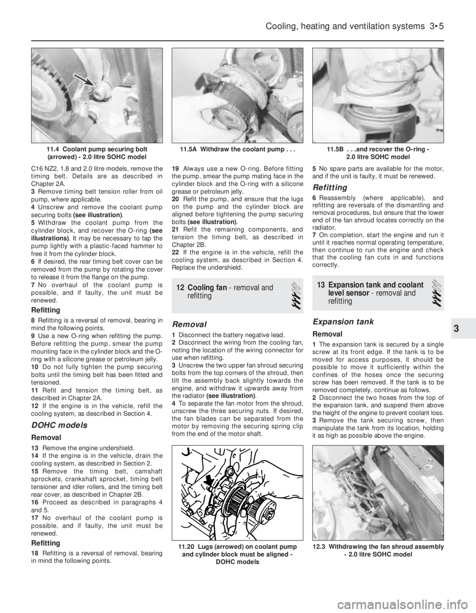
4Unscrew and remove the coolant pump
securing bolts (see illustration).
5Withdraw the coolant pump from the
cylinder block, and recover the O-ring (see
illustrations). It may be necessary to tap the
pump lightly with a plastic-faced hammer to
free it from the cylinder block.
6If desired, the rear timing belt cover can be
removed from the pump by rotating the cover
to release it from the flange on the pump.
7No overhaul of the coolant pump is
possible, and if faulty, the unit must be
renewed.
Refitting
8Refitting is a reversal of removal, bearing in
mind the following points.
9Use a new O-ring when refitting the pump.
Before refitting the pump, smear the pump
mounting face in the cylinder block and the O-
ring with a silicone grease or petroleum jelly.
10Do not fully tighten the pump securing
bolts until the timing belt has been fitted and
tensioned.
11Refit and tension the timing belt, as
described in Chapter 2A.
12If the engine is in the vehicle, refill the
cooling system, as described in Section 4.
DOHC models
Removal
13Remove the engine undershield.
14If the engine is in the vehicle, drain the
cooling system, as described in Section 2.
15Remove the timing belt, camshaft
sprockets, crankshaft sprocket, timing belt
tensioner and idler rollers, and the timing belt
rear cover, as described in Chapter 2B.
16Proceed as described in paragraphs 4
and 5.
17No overhaul of the coolant pump is
possible, and if faulty, the unit must be
renewed.
Refitting
18Refitting is a reversal of removal, bearing
in mind the following points.19Always use a new O-ring. Before fitting
the pump, smear the pump mating face in the
cylinder block and the O-ring with a silicone
grease or petroleum jelly.
20Refit the pump, and ensure that the lugs
on the pump and the cylinder block are
aligned before tightening the pump securing
bolts (see illustration).
21Refit the remaining components, and
tension the timing belt, as described in
Chapter 2B.
22If the engine is in the vehicle, refill the
cooling system, as described in Section 4.
Replace the undershield.
12Cooling fan - removal and
refitting
3
Removal
1Disconnect the battery negative lead.
2Disconnect the wiring from the cooling fan,
noting the location of the wiring connector for
use when refitting.
3Unscrew the two upper fan shroud securing
bolts from the top corners of the shroud, then
tilt the assembly back slightly towards the
engine, and withdraw it upwards away from
the radiator (see illustration).
4To separate the fan motor from the shroud,
unscrew the three securing nuts. If desired,
the fan blades can be separated from the
motor by removing the securing spring clip
from the end of the motor shaft.5No spare parts are available for the motor,
and if the unit is faulty, it must be renewed.
Refitting
6Reassembly (where applicable), and
refitting are reversals of the dismantling and
removal procedures, but ensure that the lower
end of the fan shroud locates correctly on the
radiator.
7On completion, start the engine and run it
until it reaches normal operating temperature,
then continue to run the engine and check
that the cooling fan cuts in and functions
correctly.
13Expansion tank and coolant
level sensor -removal and
refitting
3
Expansion tank
Removal
1The expansion tank is secured by a single
screw at its front edge. If the tank is to be
moved for access purposes, it should be
possible to move it sufficiently within the
confines of the hoses once the securing
screw has been removed. If the tank is to be
removed completely, continue as follows.
2Disconnect the two hoses from the top of
the expansion tank, and suspend them above
the height of the engine to prevent coolant loss.
3Remove the tank securing screw, then
manipulate the tank from its location, holding
it as high as possible above the engine.
Cooling, heating and ventilation systems 3•5
11.5B . . .and recover the O-ring -
2.0 litre SOHC model
12.3 Withdrawing the fan shroud assembly
- 2.0 litre SOHC model11.20 Lugs (arrowed) on coolant pump
and cylinder block must be aligned -
DOHC models
11.5A Withdraw the coolant pump . . .11.4 Coolant pump securing bolt
(arrowed) - 2.0 litre SOHC model
3
Page 237 of 525
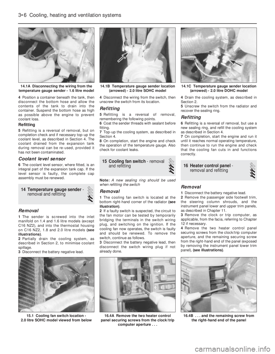
4Position a container beneath the tank, then
disconnect the bottom hose and allow the
contents of the tank to drain into the
container. Suspend the bottom hose as high
as possible above the engine to prevent
coolant loss.
Refitting
5Refitting is a reversal of removal, but on
completion check and if necessary top-up the
coolant level, as described in Section 4. The
coolant drained from the expansion tank
during removal can be re-used, provided it
has not been contaminated.
Coolant level sensor
6The coolant level sensor, where fitted, is an
integral part of the expansion tank cap. If the
level sensor is faulty, the complete cap
assembly must be renewed.
14Temperature gauge sender -
removal and refitting
2
Removal
1The sender is screwed into the inlet
manifold on 1.4 and 1.6 litre models (except
C16 NZ2), and into the thermostat housing
on C16 NZ2, 1.8 and 2.0 litre models (see
illustrations).
2Partially drain the cooling system, as
described in Section 2, to minimise coolant
spillage.
3Disconnect the battery negative lead.4Disconnect the wiring from the switch, then
unscrew the switch from its location.
Refitting
5Refitting is a reversal of removal,
remembering the following points.
6Coat the sender threads with sealant before
fitting.
7Top-up the cooling system, as described in
Section 4.
8On completion, start the engine and check
the operation of the temperature gauge. Also
check for coolant leaks.
15Cooling fan switch -removal
and refitting
3
Note: A new sealing ring should be used
when refitting the switch
Removal
1The cooling fan switch is located at the
bottom right-hand corner of the radiator (see
illustration).
2If a faulty switch is suspected, the circuit to
the fan motor can be tested by temporarily
bridging the terminals in the switch wiring
plug, and switching on the ignition. If the
cooling fan now operates, the switch is faulty
and should be renewed. To remove the
switch, continue as follows.
3Disconnect the battery negative lead, then
disconnect the switch wiring plug if not
already done.4Drain the cooling system, as described in
Section 2.
5Unscrew the switch from the radiator and
recover the sealing ring.
Refitting
6Refitting is a reversal of removal, but use a
new sealing ring, and refill the cooling system
as described in Section 4.
7On completion, start the engine and run it
until it reaches normal operating temperature,
then continue to run the engine and check
that the cooling fan cuts in and functions
correctly.
16Heater control panel -
removal and refitting
3
Removal
1Disconnect the battery negative lead.
2Remove the passenger side footwell trim,
the steering column shrouds, and the
instrument panel lower and upper trim panels,
as described in Chapter 11.
3Remove the clock or trip computer, as
applicable, from the facia, referring to Chapter
12 if necessary.
4Remove the two heater control panel
securing screws from the clock/trip computer
aperture, and the remaining securing screw
from the right-hand end of the panel (exposed
by removing the instrument panel lower trim
panel), (see illustrations).
3•6Cooling, heating and ventilation systems
14.1A Disconnecting the wiring from the
temperature gauge sender - 1.6 litre model14.1C Temperature gauge sender location
(arrowed) - 2.0 litre DOHC model
16.4B . . . and the remaining screw from
the right-hand end of the panel16.4A Remove the two heater control
panel securing screws from the clock/trip
computer aperture . . .15.1 Cooling fan switch location -
2.0 litre SOHC model viewed from below
14.1B Temperature gauge sender location
(arrowed) - 2.0 litre SOHC model
Page 238 of 525
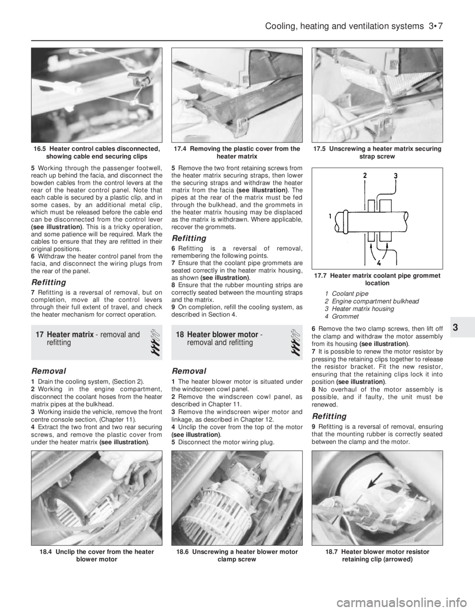
5Working through the passenger footwell,
reach up behind the facia, and disconnect the
bowden cables from the control levers at the
rear of the heater control panel. Note that
each cable is secured by a plastic clip, and in
some cases, by an additional metal clip,
which must be released before the cable end
can be disconnected from the control lever
(see illustration). This is a tricky operation,
and some patience will be required. Mark the
cables to ensure that they are refitted in their
original positions.
6Withdraw the heater control panel from the
facia, and disconnect the wiring plugs from
the rear of the panel.
Refitting
7Refitting is a reversal of removal, but on
completion, move all the control levers
through their full extent of travel, and check
the heater mechanism for correct operation.
17Heater matrix -removal and
refitting
3
Removal
1Drain the cooling system, (Section 2).
2Working in the engine compartment,
disconnect the coolant hoses from the heater
matrix pipes at the bulkhead.
3Working inside the vehicle, remove the front
centre console section, (Chapter 11).
4Extract the two front and two rear securing
screws, and remove the plastic cover from
under the heater matrix (see illustration).5Remove the two front retaining screws from
the heater matrix securing straps, then lower
the securing straps and withdraw the heater
matrix from the facia (see illustration). The
pipes at the rear of the matrix must be fed
through the bulkhead, and the grommets in
the heater matrix housing may be displaced
as the matrix is withdrawn. Where applicable,
recover the grommets.
Refitting
6Refitting is a reversal of removal,
remembering the following points.
7Ensure that the coolant pipe grommets are
seated correctly in the heater matrix housing,
as shown (see illustration).
8Ensure that the rubber mounting strips are
correctly seated between the mounting straps
and the matrix.
9On completion, refill the cooling system, as
described in Section 4.
18Heater blower motor -
removal and refitting
3
Removal
1The heater blower motor is situated under
the windscreen cowl panel.
2Remove the windscreen cowl panel, as
described in Chapter 11.
3Remove the windscreen wiper motor and
linkage, as described in Chapter 12.
4Unclip the cover from the top of the motor
(see illustration).
5Disconnect the motor wiring plug.6Remove the two clamp screws, then lift off
the clamp and withdraw the motor assembly
from its housing (see illustration).
7It is possible to renew the motor resistor by
pressing the retaining clips together to release
the resistor bracket. Fit the new resistor,
ensuring that the retaining clips lock it into
position (see illustration).
8No overhaul of the motor assembly is
possible, and if faulty, the unit must be
renewed.
Refitting
9Refitting is a reversal of removal, ensuring
that the mounting rubber is correctly seated
between the clamp and the motor.
Cooling, heating and ventilation systems 3•7
17.5 Unscrewing a heater matrix securing
strap screw
18.6 Unscrewing a heater blower motor
clamp screw18.7 Heater blower motor resistor
retaining clip (arrowed)18.4 Unclip the cover from the heater
blower motor
17.7 Heater matrix coolant pipe grommet
location
1 Coolant pipe
2 Engine compartment bulkhead
3 Heater matrix housing
4 Grommet
17.4 Removing the plastic cover from the
heater matrix16.5 Heater control cables disconnected,
showing cable end securing clips
3
Page 243 of 525

REF•4General Repair Procedures
Whenever servicing, repair or overhaul work
is carried out on the car or its components, it is
necessary to observe the following procedures
and instructions. This will assist in carrying out
the operation efficiently and to a professional
standard of workmanship.
Joint mating faces and gaskets
When separating components at their
mating faces, never insert screwdrivers or
similar implements into the joint between the
faces in order to prise them apart. This can
cause severe damage which results in oil
leaks, coolant leaks, etc upon reassembly.
Separation is usually achieved by tapping
along the joint with a soft-faced hammer in
order to break the seal. However, note that this
method may not be suitable where dowels are
used for component location.
Where a gasket is used between the mating
faces of two components, ensure that it is
renewed on reassembly, and fit it dry unless
otherwise stated in the repair procedure. Make
sure that the mating faces are clean and dry,
with all traces of old gasket removed. When
cleaning a joint face, use a tool which is not
likely to score or damage the face, and remove
any burrs or nicks with an oilstone or fine file.
Make sure that tapped holes are cleaned
with a pipe cleaner, and keep them free of
jointing compound, if this is being used, unless
specifically instructed otherwise.
Ensure that all orifices, channels or pipes
are clear, and blow through them, preferably
using compressed air.
Oil seals
Oil seals can be removed by levering them
out with a wide flat-bladed screwdriver or
similar implement. Alternatively, a number of
self-tapping screws may be screwed into the
seal, and these used as a purchase for pliers
or some similar device in order to pull the seal
free.
Whenever an oil seal is removed from its
working location, either individually or as part
of an assembly, it should be renewed.
The very fine sealing lip of the seal is easily
damaged, and will not seal if the surface it
contacts is not completely clean and free from
scratches, nicks or grooves.
Protect the lips of the seal from any surface
which may damage them in the course of
fitting. Use tape or a conical sleeve where
possible. Lubricate the seal lips with oil before
fitting and, on dual-lipped seals, fill the space
between the lips with grease.
Unless otherwise stated, oil seals must be
fitted with their sealing lips toward the
lubricant to be sealed.
Use a tubular drift or block of wood of the
appropriate size to install the seal and, if the
seal housing is shouldered, drive the seal
down to the shoulder. If the seal housing is
unshouldered, the seal should be fitted with its
face flush with the housing top face (unless
otherwise instructed).
Screw threads and fastenings
Seized nuts, bolts and screws are quite a
common occurrence where corrosion has set
in, and the use of penetrating oil or releasing
fluid will often overcome this problem if the
offending item is soaked for a while before
attempting to release it. The use of an impact
driver may also provide a means of releasing
such stubborn fastening devices, when used
in conjunction with the appropriate
screwdriver bit or socket. If none of these
methods works, it may be necessary to resort
to the careful application of heat, or the use of
a hacksaw or nut splitter device.
Studs are usually removed by locking two
nuts together on the threaded part, and then
using a spanner on the lower nut to unscrew
the stud. Studs or bolts which have broken off
below the surface of the component in which
they are mounted can sometimes be removed
using a proprietary stud extractor. Always
ensure that a blind tapped hole is completely
free from oil, grease, water or other fluid
before installing the bolt or stud. Failure to do
this could cause the housing to crack due to
the hydraulic action of the bolt or stud as it is
screwed in.
When tightening a castellated nut to accept
a split pin, tighten the nut to the specified
torque, where applicable, and then tighten
further to the next split pin hole. Never slacken
the nut to align the split pin hole, unless stated
in the repair procedure.
When checking or retightening a nut or bolt
to a specified torque setting, slacken the nut
or bolt by a quarter of a turn, and then
retighten to the specified setting. However,
this should not be attempted where angular
tightening has been used.
For some screw fastenings, notably cylinder
head bolts or nuts, torque wrench settings are
no longer specified for the latter stages of
tightening, “angle-tightening” being called up
instead. Typically, a fairly low torque wrench
setting will be applied to the bolts/nuts in
the correct sequence, followed by one or
more stages of tightening through specified
angles.
Locknuts, locktabs and washers
Any fastening which will rotate against a
component or housing in the course of
tightening should always have a washer
between it and the relevant component or
housing.
Spring or split washers should always be
renewed when they are used to lock a critical
component such as a big-end bearing
retaining bolt or nut. Locktabs which are
folded over to retain a nut or bolt should
always be renewed.
Self-locking nuts can be re-used in non-
critical areas, providing resistance can be felt
when the locking portion passes over the bolt
or stud thread. However, it should be noted
that self-locking stiffnuts tend to lose theireffectiveness after long periods of use, and in
such cases should be renewed as a matter of
course.
Split pins must always be replaced with new
ones of the correct size for the hole.
When thread-locking compound is found on
the threads of a fastener which is to be re-
used, it should be cleaned off with a wire
brush and solvent, and fresh compound
applied on reassembly.
Special tools
Some repair procedures in this manual
entail the use of special tools such as a press,
two or three-legged pullers, spring
compressors, etc. Wherever possible, suitable
readily-available alternatives to the
manufacturer’s special tools are described,
and are shown in use. Unless you are highly-
skilled and have a thorough understanding of
the procedures described, never attempt to
bypass the use of any special tool when the
procedure described specifies its use. Not
only is there a very great risk of personal injury,
but expensive damage could be caused to the
components involved.
Environmental considerations
When disposing of used engine oil, brake
fluid, antifreeze, etc, give due consideration to
any detrimental environmental effects. Do not,
for instance, pour any of the above liquids
down drains into the general sewage system,
or onto the ground to soak away. Many local
council refuse tips provide a facility for waste
oil disposal, as do some garages. If none of
these facilities are available, consult your local
Environmental Health Department for further
advice.
With the universal tightening-up of
legislation regarding the emission of
environmentally-harmful substances from
motor vehicles, most current vehicles have
tamperproof devices fitted to the main
adjustment points of the fuel system. These
devices are primarily designed to prevent
unqualified persons from adjusting the fuel/air
mixture, with the chance of a consequent
increase in toxic emissions. If such devices are
encountered during servicing or overhaul, they
should, wherever possible, be renewed or
refitted in accordance with the vehicle
manufacturer’s requirements or current
legislation.
Note: It is
antisocial and
illegal to dump
oil down the
drain. To find
the location of
your local oil
recycling
bank, call this
number free.
Page 251 of 525
Engine
m mEngine fails to rotate when attempting to start
m mEngine rotates, but will not start
m mEngine difficult to start when cold
m mEngine difficult to start when hot
m mStarter motor noisy or excessively rough in engagement
m mEngine starts, but stops immediately
m mEngine idles erratically
m mEngine misfires at idle speed
m mEngine misfires throughout the driving speed range
m mEngine hesitates on acceleration
m mEngine stalls
m mEngine lacks power
m mEngine backfires
m mOil pressure warning light illuminated with engine running
m mEngine runs-on after switching off
m mEngine noises
Cooling system
m
mOverheating
m mOvercooling
m mExternal coolant leakage
m mInternal coolant leakage
m mCorrosion
Fuel and exhaust systems
m
mExcessive fuel consumption
m mFuel leakage and/or fuel odour
m mExcessive noise or fumes from exhaust system
Clutch
m
mPedal travels to floor - no pressure or very little resistance
m mClutch fails to disengage (unable to select gears)
m mClutch slips (engine speed increases, with no increase in vehicle
speed)
m mJudder as clutch is engaged
m mNoise when depressing or releasing clutch pedal
Manual transmission
m
mNoisy in neutral with engine running
m mNoisy in one particular gear
m mDifficulty engaging gears
m mJumps out of gear
m mVibration
m mLubricant leaks
Automatic transmission
m
mFluid leakage
m mTransmission fluid brown, or has burned smell
m mGeneral gear selection problems
m mTransmission will not downshift (kickdown) with accelerator fully
depressed
m mEngine will not start in any gear, or starts in gears other than Park
or Neutral
m mTransmission slips, shifts roughly, is noisy, or has no drive in
forward or reverse gears
Driveshafts
m mClicking or knocking noise on turns (at slow speed on full-lock)
m mVibration when accelerating or decelerating
Braking system
m
mVehicle pulls to one side under braking
m mNoise (grinding or high-pitched squeal) when brakes applied
m mExcessive brake pedal travel
m mBrake pedal feels spongy when depressed
m mExcessive brake pedal effort required to stop vehicle
m mJudder felt through brake pedal or steering wheel when braking
m mBrakes binding
m mRear wheels locking under normal braking
Suspension and steering systems
m
mVehicle pulls to one side
m mWheel wobble and vibration
m mExcessive pitching and/or rolling around corners, or during
braking
m mWandering or general instability
m mExcessively stiff steering
m mExcessive play in steering
m mLack of power assistance
m mTyre wear excessive
Electrical system
m
mBattery will not hold a charge for more than a few days
m mIgnition/no-charge warning light remains illuminated with engine
running
m mIgnition/no-charge warning light fails to come on
m mLights inoperative
m mInstrument readings inaccurate or erratic
m mHorn inoperative, or unsatisfactory in operation
m mWindscreen/tailgate wipers inoperative, or unsatisfactory in
operation
m mWindscreen/tailgate washers inoperative, or unsatisfactory in
operation
m mElectric windows inoperative, or unsatisfactory in operation
m mCentral locking system inoperative, or unsatisfactory in operation
The vehicle owner who does his or her own maintenance according to
the recommended service schedules should not have to use this section
of the manual very often. Modern component reliability is such that,
provided those items subject to wear or deterioration are inspected or
renewed at the specified intervals, sudden failure is comparatively rare.
Faults do not usually just happen as a result of sudden failure, but
develop over a period of time. Major mechanical failures in particular are
usually preceded by characteristic symptoms over hundreds or even
thousands of miles. Those components that do occasionally fail without
warning are often small and easily carried in the vehicle.
With any fault-finding, the first step is to decide where to begininvestigations. Sometimes this is obvious, but on other occasions, a
little detective work will be necessary. The owner who makes half a
dozen haphazard adjustments or replacements may be successful in
curing a fault (or its symptoms). However, will be none the wiser if the
fault recurs, and ultimately may have spent more time and money than
was necessary. A calm and logical approach will be found to be more
satisfactory in the long run. Always take into account any warning
signs or abnormalities that may have been noticed in the period
preceding the fault - power loss, high or low gauge readings, unusual
smells, etc. - and remember that failure of components such as fuses
or spark plugs may only be pointers to some underlying fault.
REF•12Fault Finding
Introduction