1988 OPEL CALIBRA coolant
[x] Cancel search: coolantPage 213 of 525
32Release the securing clips and remove the
main outer timing belt cover, then unclip the
smaller outer timing belt cover from the
coolant pump.
33Turn the crankshaft through at least
quarter of a turn clockwise using a socket or
spanner on the crankshaft sprocket bolt.
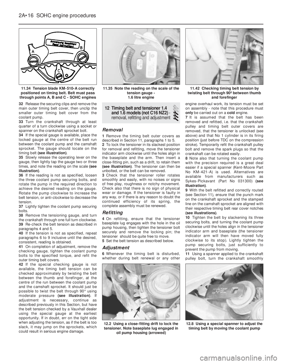
34If the special gauge is available, place the
locked gauge at the centre of the belt run
between the coolant pump and the camshaft
sprocket. The gauge should locate on the
timing belt (see illustration).
35Slowly release the operating lever on the
gauge, then lightly tap the gauge two or three
times, and note the reading on the scale (see
illustration).
36If the reading is not as specified, loosen
the three coolant pump securing bolts, and
rotate the pump in the required direction to
achieve the desired reading on the gauge.
Rotate the pump clockwise to increase the
belt tension, or anti-clockwise to decrease the
tension.
37Lightly tighten the coolant pump securing
bolts.
38Remove the tensioning gauge, and turn
the crankshaft through one full turn clockwise.
39Re-check the belt tension as described in
paragraphs 4 and 5.
40If the tension is not as specified, repeat
paragraphs 6 to 9 inclusive until the desired,
consistent, reading is obtained.
41On completion of adjustment, remove the
checking gauge, tighten the coolant pump
bolts to the specified torque, and refit the
outer timing belt covers.
42If the special checking gauge is not
available, the timing belt tension can be
checked approximately by twisting the belt
between the thumb and forefinger, at the
centre of the run between the coolant pump
and the camshaft sprocket. It should just be
possible to twist the belt through 90°using
moderate pressure (see illustration). If
adjustment is necessary, continue as
described previously in this Section, but have
the belt tension checked by a Vauxhall dealer
using the special gauge at the earliest
opportunity. If in doubt, err on the tight side
when adjusting the tension, as if the belt is too
slack, it may jump on the sprockets, which
could result in serious engine damage.12Timing belt and tensioner 1.4
and 1.6 models (not C16 NZ2) -
removal, refitting and adjustment
3
Removal
1Remove the timing belt outer covers as
described in Section 11, paragraphs 1 to 5.
2To lock the tensioner in its slackest position
for removal and refitting, move the tensioner
indicator arm clockwise until the holes align in
the baseplate and the arm. Then insert a
close-fitting pin, such as a drift, to retain them
(see illustration). The tensioner can then be
unbolted, or the belt can be removed.
3Check that the tensioner roller rotates
smoothly and easily, with no noises or signs
of free play, roughness or notchy movement.
Check also that there is no sign of physical
wear or damage. If the tensioner is faulty in
any way, or if there is any reason to doubt the
continued efficiency of its spring, the
complete assembly must be renewed.
Refitting
4On refitting, ensure that the tensioner
baseplate lug engages with the hole in the oil
pump housing, then tighten the tensioner bolt
securely and remove the locking pin; the
tensioner should be quite free to move.
5Set the belt tension as described below.
Adjustment
6Whenever the timing belt is disturbed,
whether during belt renewal or any otherengine overhaul work, its tension must be set
on assembly - note that this procedure must
only be carried out on a cold engine.
7It is assumed that the belt has been
removed and refitted, i.e. that the crankshaft
pulley and timing belt outer covers are
removed, that the tensioner is unlocked (see
above) and that No 1 cylinder is in its firing
position (just before TDC on the compression
stroke). Temporarily refit the crankshaft pulley
bolt and remove the spark plugs so that the
crankshaft can be rotated easily.
8Note also that turning the coolant pump
with the precision required is a great deal
easier if a special spanner (Kent-Moore Part
No KM-421-A) is used. Alternatives are
available from manufacturers such as
Sykes-Pickavant (Part No 031300) (see
illustration).
9With the belt refitted and correctly routed
(see Section 11), ensure that the punch mark
on the crankshaft sprocket and the stamped
line on the camshaft sprocket are aligned with
their respective timing belt rear cover notches
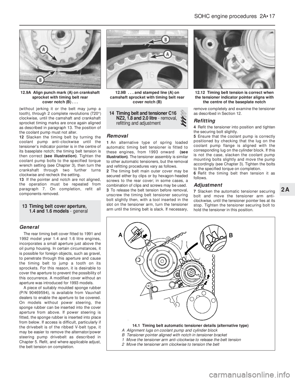
(see illustrations).
10Tighten the belt by slackening its three
securing bolts, and turning the coolant pump
clockwise until the holes align in the tensioner
indicator arm and baseplate (the tensioner
indicator arm will then have moved fully
clockwise to its stop). Lightly tighten the
pump securing bolts, just sufficiently to
prevent the pump from moving.
11Using a spanner applied to the crankshaft
pulley bolt, turn the crankshaft smoothly
2A•16SOHC engine procedures
11.34 Tension blade KM-510-A correctly
positioned on timing belt. Belt must pass
through points A, B and C - SOHC engines11.42 Checking timing belt tension by
twisting belt through 90º between thumb
and forefinger
12.8 Using a special spanner to adjust the
timing belt by moving the coolant pump12.2 Using a close-fitting drift to lock the
tensioner. Note baseplate lug engaged in
oil pump housing (arrowed)
11.35 Note the reading on the scale of the
tension gauge -
1.6 litre engine
Page 214 of 525
(without jerking it or the belt may jump a
tooth), through 2 complete revolutions (720°)
clockwise, until the camshaft and crankshaft
sprocket timing marks are once again aligned
as described in paragraph 13. The position of
the coolant pump must not alter.
12Slacken the timing belt by turning the
coolant pump anti-clockwise until the
tensioner’s indicator pointer is in the centre of
its baseplate notch; the timing belt tension is
then correct (see illustration). Tighten the
coolant pump bolts to the specified torque
wrench setting (see Chapter 3), then turn the
crankshaft through two further turns
clockwise and recheck the setting.
13If the pointer and notch are not aligned,
the operation must be repeated from
paragraph 7. On completion, refit all
components removed.
13Timing belt cover aperture,
1.4 and 1.6 models - general
General
The rear timing belt cover fitted to 1991 and
1992 model year 1.4 and 1.6 litre engines,
incorporates a small aperture just above the
oil pump housing. In certain circumstances, it
is possible for foreign objects, such as gravel,
to penetrate through this aperture and cause
the timing belt to jump a tooth on its
sprockets. For this reason, it is desirable to
cover the aperture to prevent the possibility of
this occurrence. A modified cover without an
aperture was introduced for 1993 models.
A piece of suitably moulded sponge rubber
(P/N 90469594), is available from Vauxhall
dealers to enable the aperture to be covered.
On models without power steering, the
sponge rubber can be inserted into the cover
aperture from above. If power steering is
fitted, the sponge rubber is inserted into place
from below. If access is difficult, particularly if
the drivebelt is of the ribbed V-belt type, it
may be easier to remove the alternator/power
steering pump drivebelt as described in
Chapter 5. Refit, and where applicable adjust,
the belt tension on completion.
14Timing belt and tensioner C16
NZ2, 1.8 and 2.0 litre - removal,
refitting and adjustment
3
Removal
1An alternative type of spring loaded
automatic timing belt tensioner is fitted to
these engines, from 1993 onward (see
illustration). The tensioner assembly is similar
to other automatic tensioners, but the removal
and refitting procedures vary as follows.
2The timing belt main outer cover may be
secured either by clips or by hexagon-headed
screws to the rear cover; in some cases, a
combination of clips and screws may be used.
3To release the belt tension before removal,
unscrew the timing belt tensioner securing
bolt slightly then, with a tool inserted in the
slot on the tensioner arm, turn the tensioner
arm until the timing belt is slack. If necessary,remove completely and examine the tensioner
as described in Section 12.
Refitting
4Refit the tensioner into position and tighten
the securing bolt slightly.
5Ensure that the coolant pump is correctly
positioned by checking that the lug on the
coolant pump flange is aligned with the
corresponding lug on the cylinder block. If this
is not the case, slacken the coolant pump
mounting bolts slightly and move the pump
accordingly (see Chapter 3). Tighten the bolts
to the specified torque on completion.
6Refit the timing belt then tension it as
follows.
Adjustment
7Slacken the automatic tensioner securing
bolt and move the tensioner arm anti-
clockwise, until the tensioner pointer lies at its
stop. Tighten the tensioner securing bolt to
hold the tensioner in this position.
SOHC engine procedures 2A•17
12.12 Timing belt tension is correct when
the tensioner indicator pointer aligns with
the centre of the baseplate notch12.9B . . . and stamped line (A) on
camshaft sprocket with timing belt rear
cover notch (B)12.9A Align punch mark (A) on crankshaft
sprocket with timing belt rear
cover notch (B) . . .
2A
14.1 Timing belt automatic tensioner details (alternative type)
A Alignment lugs on coolant pump and cylinder block
B Tensioner pointer aligned with notch in tensioner bracket
1 Move the tensioner arm anti-clockwise to release the belt tension
2 Move the tensioner arm clockwise to tension the belt
Page 217 of 525
supported to one side out of the way, thus
avoiding the need to disconnect the relevant
hoses, pipes and wiring.
5If the cylinder head is to be removed
complete with the manifolds, disconnect all
relevant hoses, pipes and wiring from the inlet
manifold and associated components,
referring to Chapter 4A or 4B. On carburettor
models, disconnect the hot air hose from the
shroud on the exhaust manifold. Loosen the
alternator mountings, with reference to
Chapter 5, then unbolt the upper alternator
mounting from the inlet manifold.
6If the inlet manifold is to be left in the engine
compartment, continue as follows, otherwise
go on to paragraph 15.
7Disconnect the air cleaner trunking from the
air box on the carburettor or throttle body, or
directly from the throttle body (as applicable),
and disconnect the camshaft cover breather
hose that runs to the carburettor or throttle
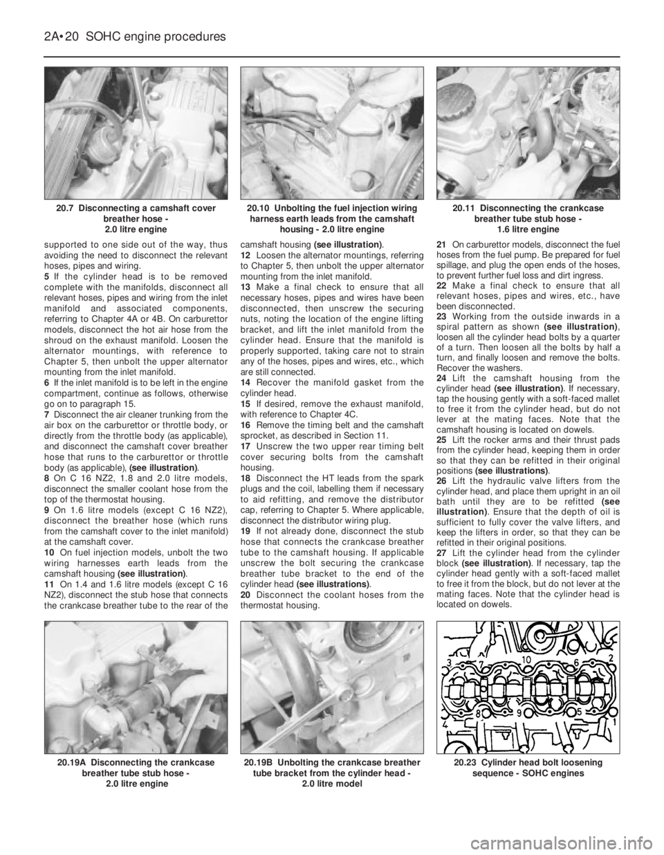
body (as applicable), (see illustration).
8On C 16 NZ2, 1.8 and 2.0 litre models,
disconnect the smaller coolant hose from the
top of the thermostat housing.
9On 1.6 litre models (except C 16 NZ2),
disconnect the breather hose (which runs
from the camshaft cover to the inlet manifold)
at the camshaft cover.
10On fuel injection models, unbolt the two
wiring harnesses earth leads from the
camshaft housing (see illustration).
11On 1.4 and 1.6 litre models (except C 16
NZ2), disconnect the stub hose that connects
the crankcase breather tube to the rear of thecamshaft housing (see illustration).
12Loosen the alternator mountings, referring
to Chapter 5, then unbolt the upper alternator
mounting from the inlet manifold.
13Make a final check to ensure that all
necessary hoses, pipes and wires have been
disconnected, then unscrew the securing
nuts, noting the location of the engine lifting
bracket, and lift the inlet manifold from the
cylinder head. Ensure that the manifold is
properly supported, taking care not to strain
any of the hoses, pipes and wires, etc., which
are still connected.
14Recover the manifold gasket from the
cylinder head.
15If desired, remove the exhaust manifold,
with reference to Chapter 4C.
16Remove the timing belt and the camshaft
sprocket, as described in Section 11.
17Unscrew the two upper rear timing belt
cover securing bolts from the camshaft
housing.
18Disconnect the HT leads from the spark
plugs and the coil, labelling them if necessary
to aid refitting, and remove the distributor
cap, referring to Chapter 5. Where applicable,
disconnect the distributor wiring plug.
19If not already done, disconnect the stub
hose that connects the crankcase breather
tube to the camshaft housing. If applicable
unscrew the bolt securing the crankcase
breather tube bracket to the end of the
cylinder head (see illustrations).
20Disconnect the coolant hoses from the
thermostat housing.21On carburettor models, disconnect the fuel
hoses from the fuel pump. Be prepared for fuel
spillage, and plug the open ends of the hoses,
to prevent further fuel loss and dirt ingress.
22Make a final check to ensure that all
relevant hoses, pipes and wires, etc., have
been disconnected.
23Working from the outside inwards in a
spiral pattern as shown (see illustration),
loosen all the cylinder head bolts by a quarter
of a turn. Then loosen all the bolts by half a
turn, and finally loosen and remove the bolts.
Recover the washers.
24Lift the camshaft housing from the
cylinder head (see illustration). If necessary,
tap the housing gently with a soft-faced mallet
to free it from the cylinder head, but do not
lever at the mating faces. Note that the
camshaft housing is located on dowels.
25Lift the rocker arms and their thrust pads
from the cylinder head, keeping them in order
so that they can be refitted in their original
positions (see illustrations).
26Lift the hydraulic valve lifters from the
cylinder head, and place them upright in an oil
bath until they are to be refitted (see
illustration). Ensure that the depth of oil is
sufficient to fully cover the valve lifters, and
keep the lifters in order, so that they can be
refitted in their original positions.
27Lift the cylinder head from the cylinder
block (see illustration). If necessary, tap the
cylinder head gently with a soft-faced mallet
to free it from the block, but do not lever at the
mating faces. Note that the cylinder head is
located on dowels.
2A•20SOHC engine procedures
20.7 Disconnecting a camshaft cover
breather hose -
2.0 litre engine20.11 Disconnecting the crankcase
breather tube stub hose -
1.6 litre engine
20.23 Cylinder head bolt loosening
sequence - SOHC engines20.19B Unbolting the crankcase breather
tube bracket from the cylinder head -
2.0 litre model20.19A Disconnecting the crankcase
breather tube stub hose -
2.0 litre engine
20.10 Unbolting the fuel injection wiring
harness earth leads from the camshaft
housing - 2.0 litre engine
Page 218 of 525
28Recover the cylinder head gasket and
discard it.
Refitting
29Clean the cylinder head and block mating
faces, and the camshaft housing and cylinder
head mating faces by careful scraping. Take
care not to damage the cylinder head and
camshaft housing, which are made of light
alloy and are easily scored. Cover the coolant
passages and other openings with masking
tape or rag to prevent dirt and carbon falling
in. Mop out all the oil from the bolt holes; if oil
is left in the holes, hydraulic pressure could
crack the block when the bolts are refitted.
30If desired, the cylinder head can be
dismantled and inspected as described in
Sections 22 and 23, and the camshaft
housing can be dismantled as described in
Section 18.31Begin refitting by locating a new gasket
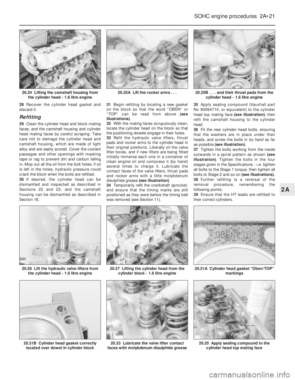
on the block so that the word “OBEN” or
“TOP” can be read from above (see
illustrations).
32With the mating faces scrupulously clean,
locate the cylinder head on the block so that
the positioning dowels engage in their holes.
33Refit the hydraulic valve lifters, thrust
pads and rocker arms to the cylinder head in
their original positions. Liberally oil the valve
lifter bores, and if new lifters are being fitted
initially immerse each one in a container of
clean engine oil and compress it (by hand)
several times to charge it. Lubricate the
contact faces of the valve lifters, thrust pads
and rocker arms with a little molybdenum
disulphide grease (see illustration).
34Temporarily refit the crankshaft sprocket,
and ensure that the timing marks are still
positioned as they were before the timing belt
was removed (see Section 11).35Apply sealing compound (Vauxhall part
No 90094714, or equivalent) to the cylinder
head top mating face (see illustration), then
refit the camshaft housing to the cylinder
head.
36Fit the new cylinder head bolts, ensuring
that the washers are in place under their
heads, and screw the bolts in by hand as far
as possible (see illustration).
37Tighten the bolts working from the inside
outwards in a spiral pattern as shown (see
illustration). Tighten the bolts in the four
stages given in the Specifications -i.e. tighten
all bolts to the Stage 1 torque, then tighten all
bolts to Stage 2 and so on (see illustrations).
38Further refitting is a reversal of the
removal procedure, remembering the
following points.
39Ensure that the HT leads are refitted to
their correct cylinders.
SOHC engine procedures 2A•21
20.25B . . . and their thrust pads from the
cylinder head - 1.6 litre engine
20.35 Apply sealing compound to the
cylinder head top mating face20.33 Lubricate the valve lifter contact
faces with molybdenum disulphide grease20.31B Cylinder head gasket correctly
located over dowel in cylinder block
20.31A Cylinder head gasket “Oben/TOP”
markings20.27 Lifting the cylinder head from the
cylinder block - 1.6 litre engine20.26 Lift the hydraulic valve lifters from
the cylinder head - 1.6 litre engine
20.25A Lift the rocker arms . . .20.24 Lifting the camshaft housing from
the cylinder head - 1.6 litre engine
2A
Page 221 of 525
23Cylinder head - inspection
and renovation
4
Note: Refer to a dealer for advice before
attempting to carry out valve grinding or valve
seat reciting operations, as these operations
may not be possible for the DIY mechanic.
This is due to the fitment of hardened valve
seats for use with unleaded petrol
Inspection
1Remember that the cylinder head is of light
alloy construction and is easily damaged, use
a blunt scraper or rotary wire brush to clean all
traces of carbon deposits from the
combustion spaces and the ports. The valve
stems and valve guides should also be freed
from any carbon deposits. Wash the
combustion spaces and ports down with
paraffin and scrape the cylinder head surface
free of any foreign matter with the side of a
steel rule, or a similar article.
2If the engine is installed in the car, clean the
pistons and the top of the cylinder bores. If
the pistons are still in the block, it is essential
that great care is taken to ensure that no
carbon gets into the cylinder bores. This could
scratch the cylinder walls or cause damage to
the pistons and rings. To ensure this does not
happen, first turn the crankshaft so that two of
the pistons are at the top of their bores. Insert
rag into the other two bores or seal them off
with paper and masking tape. The waterways
should also be covered with small pieces of
masking tape, to prevent particles of carbon
entering the cooling system and damaging the
coolant pump.
3Press a little grease into the gap between
the cylinder walls and the two pistons that are
to be worked on. With a blunt scraper,
carefully scrape away the carbon from the
piston crown, taking great care not to scratch
the aluminium. Also scrape away the carbon
from the surrounding lip of the cylinder wall.
When all carbon has been removed, scrape
away the grease that will now be
contaminated with carbon particles, taking
care not to press any into the bores. To assist
prevention of carbon build-up, the piston
crown can be polished with a metal polish.
Remove the rags or masking tape from the
other two cylinders, and turn the crankshaft
so that the two pistons that were at thebottom are now at the top. Place rag or
masking tape in the cylinders that have been
decarbonised, and continue as just described.
4Examine the heads of the valves for pitting
and burning, especially the heads of the
exhaust valves. The valve seatings should be
examined at the same time. If the pitting on
the valve and seat is very slight, the marks
can be removed by grinding the seats and
valves together with coarse, and then fine,
valve grinding paste.
5Where bad pitting has occurred to the valve
seats, it will be necessary to recut them and fit
new valves. This latter job should be entrusted
to the local dealer or engineering works. In
practice it is very seldom that the seats are so
badly worn. Normally it is the valve that is too
badly worn for refitting, and the owner can
easily buy a new set of valves and match
them to the seats by valve grinding.
Renovation
6Valve grinding is carried out as follows.
Smear a trace of coarse carborundum paste
on the seat face and apply a suction grinder
tool to the valve head. With a semi-rotary
motion, grind the valve head to its seat, lifting
the valve occasionally to redistribute the
grinding paste. When a dull matt even surface
is produced on both the valve seat and the
valve, wipe off the paste and repeat the
process with fine carborundum paste, lifting
and turning the valve to redistribute the paste
as before. A light spring placed under the
valve head will greatly ease this operation.
When a smooth unbroken ring of light grey
matt finish is produced, on both valve and
valve seat faces, the grinding operation is
complete. Carefully clean away every trace of
grinding compound, taking great care to leave
none in the ports or in the valve guides. Clean
the valves and valve seats with a
paraffin-soaked rag, then with a clean rag,
and finally, if an air line is available, blow the
valves, valve guides and valve ports clean.
7Check that all valve springs are intact. If any
one is broken, all should be renewed. Check
the free height of the springs against new
ones. If some springs are not long enough,
replace them all. Springs suffer from fatigue
and it is a good idea to renew them even if
they look serviceable. 8The cylinder head can be checked for
warping either by placing it on a piece of plate
glass or using a straight-edge and feeler
blades. If there is any doubt or if its block face
is corroded, have it re-faced by your dealer or
motor engineering works.
9On 1.8 and 2.0 litre, always renew the
sealing ring between the cylinder head and
the thermostat housing when the head is
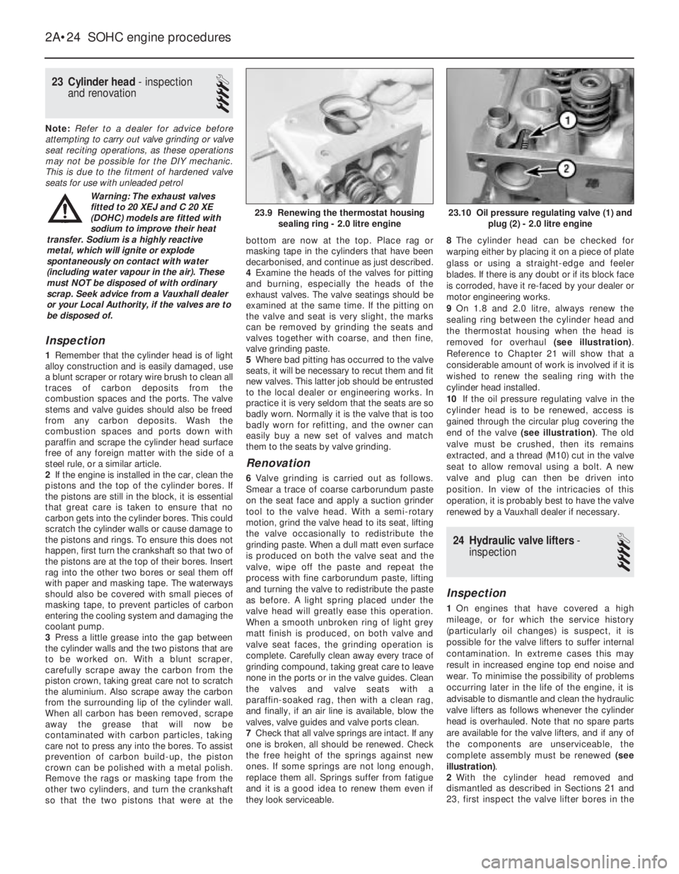
removed for overhaul (see illustration).
Reference to Chapter 21 will show that a
considerable amount of work is involved if it is
wished to renew the sealing ring with the
cylinder head installed.
10If the oil pressure regulating valve in the
cylinder head is to be renewed, access is
gained through the circular plug covering the
end of the valve (see illustration). The old
valve must be crushed, then its remains
extracted, and a thread (M10) cut in the valve
seat to allow removal using a bolt. A new
valve and plug can then be driven into
position. In view of the intricacies of this
operation, it is probably best to have the valve
renewed by a Vauxhall dealer if necessary.
24Hydraulic valve lifters -
inspection
4
Inspection
1On engines that have covered a high
mileage, or for which the service history
(particularly oil changes) is suspect, it is
possible for the valve lifters to suffer internal
contamination. In extreme cases this may
result in increased engine top end noise and
wear. To minimise the possibility of problems
occurring later in the life of the engine, it is
advisable to dismantle and clean the hydraulic
valve lifters as follows whenever the cylinder
head is overhauled. Note that no spare parts
are available for the valve lifters, and if any of
the components are unserviceable, the
complete assembly must be renewed (see
illustration).
2With the cylinder head removed and
dismantled as described in Sections 21 and
23, first inspect the valve lifter bores in the
2A•24SOHC engine procedures
23.10 Oil pressure regulating valve (1) and
plug (2) - 2.0 litre engine23.9 Renewing the thermostat housing
sealing ring - 2.0 litre engine
Warning: The exhaust valves
fitted to 20 XEJ and C 20 XE
(DOHC) models are fitted with
sodium to improve their heat
transfer. Sodium is a highly reactive
metal, which will ignite or explode
spontaneously on contact with water
(including water vapour in the air). These
must NOT be disposed of with ordinary
scrap. Seek advice from a Vauxhall dealer
or your Local Authority, if the valves are to
be disposed of.
Page 228 of 525
7If any of the ring end gaps exceed the
specified tolerance, the relevant rings will have
to be renewed, and if the ring grooves in the
pistons are worn, new pistons may be required.
8Clean out the piston ring grooves using a
piece of old piston ring as a scraper. Take
care not to scratch the surface of the pistons.
Protect your fingers, piston ring edges are
sharp. Also probe the groove oil return holes,
to ensure that they are not blocked.
9Check the cylinder bores for signs of wear
ridges towards the top of the bores. If wear
ridges are evident, and new piston rings are
being fitted, the top ring must be stepped to
clear the wear ridge, or the bore must be
de-ridged using a scraper.
10Fit the oil control ring sections with the
lower steel ring gap offset 25 to 50 mm to the
right of the spreader ring gap, and the upper
steel ring gap offset by the same distance to
the left of the spreader ring gap.
11Fit the lower compression ring, noting that
the ring is tapered or stepped. The ring should
be fitted with the word “TOP” uppermost.
12Fit the upper compression ring, and offset
the ring gap by 180°to the lower compression
ring gap. If a stepped ring is being fitted, fit
the ring with the smaller diameter of the step
uppermost.
13If new pistons are to be fitted, they must
be selected from the grades available, after
measuring the cylinder bores as described in
Section 36.
14Normally the appropriate oversize pistons
are supplied by the dealer when the block is
rebored.15Whenever new piston rings are being
installed, the glaze on the original cylinder
bores should be “broken”, using either
abrasive paper or a glaze-removing tool in an
electric drill. If abrasive paper is used, use
strokes at 60°to the bore centre line, to create
a cross-hatching effect.
34Crankshaft and bearings -
removal and refitting
4
Note: New main bearing cap bolts must be
used on refitting
Removal
1With the engine removed from the vehicle,
continue as follows.
2Remove the cylinder head, as described
previously in Section 20.
3Remove the sump, oil pick-up pipe and
sump baffle (where applicable), as described
in Section 29.
4Remove the oil pump, as described in
Section 30.
5Remove the flywheel or flexplate (if
applicable), as described in Sections 25 and
26.
6Remove the pistons and connecting rods,
as described in Section 32.
7Invert the engine so that it is standing on
the top face of the cylinder block.
8The main bearing caps are numbered 1 to 4
from the timing belt end of the engine. The
rear (flywheel end) cap is not marked. Toensure that the caps are refitted the correct
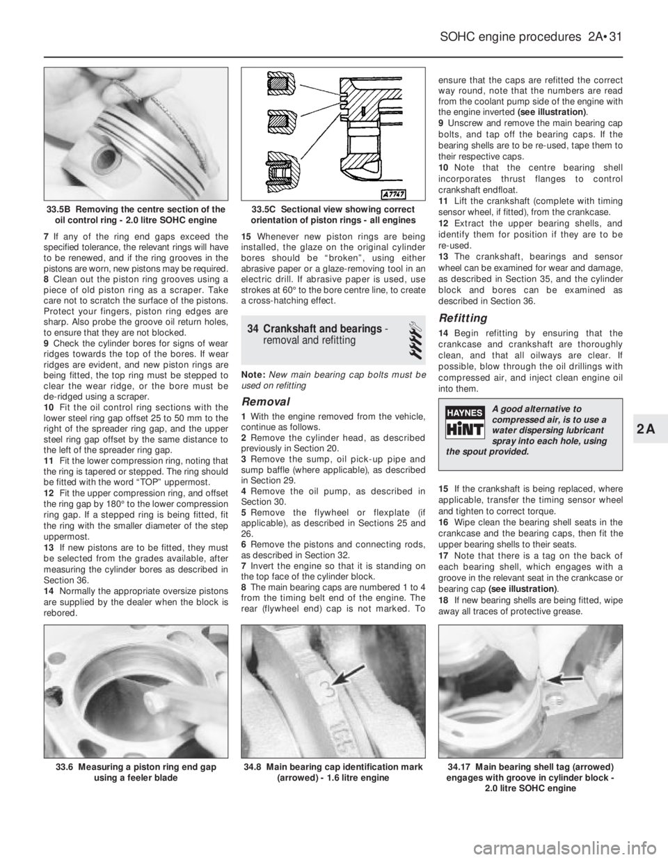
way round, note that the numbers are read
from the coolant pump side of the engine with
the engine inverted (see illustration).
9Unscrew and remove the main bearing cap
bolts, and tap off the bearing caps. If the
bearing shells are to be re-used, tape them to
their respective caps.
10Note that the centre bearing shell
incorporates thrust flanges to control
crankshaft endfloat.
11Lift the crankshaft (complete with timing
sensor wheel, if fitted), from the crankcase.
12Extract the upper bearing shells, and
identify them for position if they are to be
re-used.
13The crankshaft, bearings and sensor
wheel can be examined for wear and damage,
as described in Section 35, and the cylinder
block and bores can be examined as
described in Section 36.
Refitting
14Begin refitting by ensuring that the
crankcase and crankshaft are thoroughly
clean, and that all oilways are clear. If
possible, blow through the oil drillings with
compressed air, and inject clean engine oil
into them.
15If the crankshaft is being replaced, where
applicable, transfer the timing sensor wheel
and tighten to correct torque.
16Wipe clean the bearing shell seats in the
crankcase and the bearing caps, then fit the
upper bearing shells to their seats.
17Note that there is a tag on the back of
each bearing shell, which engages with a
groove in the relevant seat in the crankcase or
bearing cap (see illustration).
18If new bearing shells are being fitted, wipe
away all traces of protective grease.
SOHC engine procedures 2A•31
33.6 Measuring a piston ring end gap
using a feeler blade34.8 Main bearing cap identification mark
(arrowed) - 1.6 litre engine34.17 Main bearing shell tag (arrowed)
engages with groove in cylinder block -
2.0 litre SOHC engine
33.5C Sectional view showing correct
orientation of piston rings - all engines33.5B Removing the centre section of the
oil control ring - 2.0 litre SOHC engine
2A
A good alternative to
compressed air, is to use a
water dispersing lubricant
spray into each hole, using
the spout provided.
Page 231 of 525
5Note that the rubber plug located next to
the bellhousing flange on the cylinder block
covers the aperture for the installation of a
diagnostic TDC sensor. The sensor, when
connected to a monitoring unit, indicates TDC
from the position of the pins set into the
crankshaft balance weight.
37Examination and renovation
-general
4
General
1With the engine completely stripped, clean all
components and examine them for wear. Each
component should be checked, and where
necessary renewed or renovated, as described
in the relevant Sections of this Chapter.
2Renew main and big-end bearing shells as
a matter of course, unless it is known that
they have had little wear, and are in perfect
condition.
3If in doubt whether to renew a component
that is still just serviceable, consider the time
and effort that will be incurred should the
component fail at an early date after rebuild.
Obviously, the age and expected life of the
vehicle must influence the standards applied.4Gaskets, oil seals and O-rings must all be
renewed as a matter of routine. Flywheel,
cylinder head, and main and big-end bearing
cap bolts must be renewed, because of the
high stress to which they are subjected.
5Renew the engine core plugs while they are
easily accessible, if they show signs of
leakage. Knock out the old plugs with a
hammer and chisel or punch. Clean the plug
seats, smear the new plugs with sealing
compound, and tap them squarely into
position.
38Initial start-up after major
overhaul or repair
2
1Make a final check to ensure that
everything has been reconnected to the
engine, and that no rags or tools have been
left in the engine compartment.
2Check that oil and coolant levels are
correct.
3Start the engine. This may take a little longer
than usual, as fuel is pumped to the engine.
4Check that the oil pressure warning lamp
goes out when the engine starts. This may
take a few seconds as the new oil filter fills
with oil.5Run the engine at a fast tickover, and check
for leaks of oil, fuel and coolant. If a new
camshaft has been fitted, pay careful
attention to the running-in procedure given in
Section 18, paragraphs 17 and 18. Where
applicable, check the power steering and/or
automatic transmission fluid cooler unions for
leakage. Some smoke and odd smells may be
experienced, as assembly lubricants and
sealers burn off the various components.
6Bring the engine to normal operating
temperature. Check the ignition timing, idle
speed and the mixture (where applicable), as
described in Chapter 4A or 4B.
7Allow the engine to cool, then recheck the
oil and coolant levels. Top-up if necessary
8If new bearings, pistons, etc., have been
fitted, the engine should be run-in at reduced
speeds and loads for the first 500 miles (800
km) or so. It is beneficial to change the engine
oil and filter after this mileage.
2A•34SOHC engine procedures
Page 232 of 525
3
System type . . . . . . . . . . . . . . . . . . . . . . . . . . . . . . . . . . . . . . . . . . . Pressurised, with remote expansion tank. Coolant pump driven by
timing belt
Coolant
Type/specification (all models) . . . . . . . . . . . . . . . . . . . . . . . . . . . . . . . . See Lubricants and fluidsin “Weekly checks”
Capacity . . . . . . . . . . . . . . . . . . . . . . . . . . . . . . . . . . . . . . . . . . . . . . . . . See Chapter 1 Specifications
Thermostat
Starts to open at (all models) . . . . . . . . . . . . . . . . . . . . . . . . . . . . . . . . . 92°C
Fully open at (all models) . . . . . . . . . . . . . . . . . . . . . . . . . . . . . . . . . . . . 107°C
Operating temperature (approx.) . . . . . . . . . . . . . . . . . . . . . . . . . . . . . . 80°C
Expansion tank cap
Opening pressure (all models) . . . . . . . . . . . . . . . . . . . . . . . . . . . . . . . . 1.20 to 1.35 bar
Boiling point . . . . . . . . . . . . . . . . . . . . . . . . . . . . . . . . . . . . . . . . . . . . . . 125°C
Cooling fan switch
Switches on at (all models) . . . . . . . . . . . . . . . . . . . . . . . . . . . . . . . . . . . 100°C
Switches off at (all models) . . . . . . . . . . . . . . . . . . . . . . . . . . . . . . . . . . . 95°C
Torque wrench settingsNm lbf ft
Coolant pump bolts:
1.4 and 1.6 litre models
(except C16 NZ2), (M6) . . . . . . . . . . . . . . . . . . . . . . . . . . . . . . . . . . 8 6
C16 NZ2, 1.8 and 2.0 litre models (M8) . . . . . . . . . . . . . . . . . . . . . . . 25 18
Oil pipes to radiator . . . . . . . . . . . . . . . . . . . . . . . . . . . . . . . . . . . . . . . . 22 16
Outlet to thermostat housing,
C16 NZ2, 1.8 and 2.0 litre models . . . . . . . . . . . . . . . . . . . . . . . . . . . 8 6
Temperature sender . . . . . . . . . . . . . . . . . . . . . . . . . . . . . . . . . . . . . . . . 10 7
Temperature sensor . . . . . . . . . . . . . . . . . . . . . . . . . . . . . . . . . . . . . . . . 11 8
Thermostat housing to cylinder head:
1.4 and 1.6 litre models (except C16 NZ2) . . . . . . . . . . . . . . . . . . . . . 10 7
C16 NZ2, 1.8 and 2.0 litre models . . . . . . . . . . . . . . . . . . . . . . . . . . . 15 11
Chapter 3
Cooling, heating and ventilation systems
Coolant mixture - general . . . . . . . . . . . . . . . . . . . . . . . . . . . . . . . . . . .5
Coolant pump - removal and refitting . . . . . . . . . . . . . . . . . . . . . . . . .11
Cooling fan - removal and refitting . . . . . . . . . . . . . . . . . . . . . . . . . . .12
Cooling fan switch - removal and refitting . . . . . . . . . . . . . . . . . . . . .15
Cooling system - draining . . . . . . . . . . . . . . . . . . . . . . . . . . . . . . . . . . .2
Cooling system - filling . . . . . . . . . . . . . . . . . . . . . . . . . . . . . . . . . . . . .4
Cooling system - flushing . . . . . . . . . . . . . . . . . . . . . . . . . . . . . . . . . . .3
Expansion tank and coolant level sensor - removal and refitting . . . .13
Facia ventilation nozzles - removal and refitting . . . . . . . . . . . . . . . .19
General description . . . . . . . . . . . . . . . . . . . . . . . . . . . . . . . . . . . . . . .1Heater blower motor - removal and refitting . . . . . . . . . . . . . . . . . . .18
Heater control panel - removal and refitting . . . . . . . . . . . . . . . . . . . .16
Heater matrix - removal and refitting . . . . . . . . . . . . . . . . . . . . . . . . .17
Radiator (automatic transmission) - removal and refitting . . . . . . . . . .7
Radiator (manual transmission) - removal and refitting . . . . . . . . . . . .6
Radiator - inspection and cleaning . . . . . . . . . . . . . . . . . . . . . . . . . . . .8
Temperature gauge sender - removal and refitting . . . . . . . . . . . . . .14
Thermostat - removal and refitting . . . . . . . . . . . . . . . . . . . . . . . . . . . .9
Thermostat - testing . . . . . . . . . . . . . . . . . . . . . . . . . . . . . . . . . . . . . .10
3•1
Specifications Contents
Easy,suitable for
novice with little
experienceFairly easy,suitable
for beginner with
some experienceFairly difficult,
suitable for competent
DIY mechanic
Difficult,suitable for
experienced DIY
mechanicVery difficult,
suitable for expert DIY
or professional
Degrees of difficulty
54321