1988 OPEL CALIBRA steering
[x] Cancel search: steeringPage 149 of 525
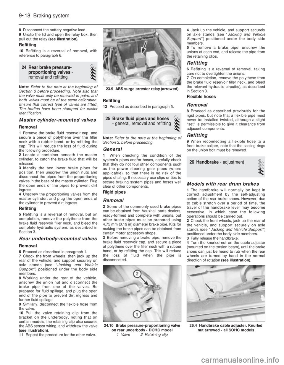
8Disconnect the battery negative lead.
9Unclip the lid and open the relay box, then
pull out the relay (see illustration).
Refitting
10Refitting is a reversal of removal, with
reference to paragraph 6.
24Rear brake pressure-
proportioning valves -
removal and refitting
4
Note: Refer to the note at the beginning of
Section 3 before proceeding. Note also that
the valve must only be renewed in pairs, and
both valves must be of the same calibration.
Ensure that correct type of valves are fitted.
The bodies have been stamped for easier
identification.
Master cylinder-mounted valves
Removal
1Remove the brake fluid reservoir cap, and
secure a piece of polythene over the filler
neck with a rubber band, or by refitting the
cap. This will reduce the loss of fluid during
the following procedure.
2Locate a container beneath the master
cylinder, to catch the brake fluid that will be
released.
3Identify the two lower brake pipes for
position, then unscrew the union nuts and
disconnect the pipes from the proportioning
valves in the base of the master cylinder. Plug
the open ends of the pipes to prevent dirt
ingress.
4Unscrew the proportioning valves from the
master cylinder, and plug the open ends of
the cylinder to prevent dirt ingress.
Refitting
5Refitting is a reversal of removal, but on
completion, remove the polythene from the
brake fluid reservoir filler neck, and bleed the
complete hydraulic system, as described in
Section 3.
Rear underbody-mounted valves
Removal
6Proceed as described in paragraph 1.
7Chock the front wheels, then jack up the
rear of the vehicle, and support securely on
axle stands (see “Jacking and Vehicle
Support”) positioned under the body side
members.
8Working under the rear of the vehicle,
unscrew the union nut and disconnect the
brake pipe from one of the valves. Be
prepared for fluid spillage, and plug the open
end of the pipe to prevent dirt ingress and
further fluid spillage.
9Similarly, disconnect the flexible hose from
the valve.
10Pull the valve retaining clip from the
bracket on the underbody, noting that on
certain models, the retaining clip also secures
the ABS sensor wiring, and withdraw the valve
(see illustration).
11Repeat the procedure for the other valve.
Refitting
12Proceed as described in paragraph 5.
25Brake fluid pipes and hoses
- general, removal and refitting
4
Note: Refer to the note at the beginning of
Section 3, before proceeding.
General
1When checking the condition of the
system’s pipes and/or hoses, carefully check
that they do not foul other components such
as the power steering gear pipes (where
applicable), so that there is no risk of the
pipes chafing. If necessary use clips or ties to
secure braking system pipes and hoses well
clear of other components.
Rigid pipes
Removal
2Some of the commonly used brake pipes
can be obtained from Vauxhall parts dealers,
ready-formed and complete with unions, but
other brake pipes must be prepared using
4.75 mm (0.19 in) diameter brake pipe. Kits for
making the brake pipes can be obtained from
certain motor accessory shops.
3Before removing a brake pipe, remove the
brake fluid reservoir cap, and secure a piece
of polythene over the filler neck with a rubber
band, or by refitting the cap. This will reduce
the loss of fluid when the pipe is
disconnected.4Jack up the vehicle, and support securely
on axle stands (see “Jacking and Vehicle
Support”) positioned under the body side
members.
5To remove a brake pipe, unscrew the
unions at each end, and release the pipe from
the retaining clips.
Refitting
6Refitting is a reversal of removal, taking
care not to overtighten the unions.
7On completion, remove the polythene from
the brake fluid reservoir filler neck, and bleed
the relevant hydraulic circuit(s), as described
in Section 3.
Flexible hoses
Removal
8Proceed as described previously for the
rigid pipes, but note that a flexible pipe must
never be installed twisted, although a slight
“set” is permissible to give it clearance from
adjacent components.
Refitting
9When reconnecting a flexible hose to a
front brake caliper, note that the sealing rings
on the union bolt must be renewed.
26Handbrake - adjustment
2
Models with rear drum brakes
1The handbrake will normally be kept in
correct adjustment by the self-adjusting
action of the rear brake shoes. However, due
to cable stretch over a period of time, the
travel of the handbrake lever may become
excessive, in which case the following
operations should be carried out.
2Chock the front wheels, jack up the rear of
the vehicle, and support securely on axle
stands (see “Jacking and Vehicle Support”)
positioned under the body side members.
3Fully release the handbrake.
4Turn the knurled nut on the cable adjuster
(mounted on the torsion beam), until the brake
shoes can just be heard to rub when the rear
wheels are turned by hand in the normal
direction of rotation (see illustration).
9•18Braking system
23.9 ABS surge arrester relay (arrowed)
26.4 Handbrake cable adjuster. Knurled
nut arrowed - all SOHC models24.10 Brake pressure-proportioning valve
on rear underbody - DOHC model
1 Valve 2 Retaining clip
Page 172 of 525
1
Chapter 1
Routine maintenance and servicing
Air cleaner element - renewal . . . . . . . . . . . . . . . . . . . . . . . . . . . . . . .27
Air inlet temperature control check . . . . . . . . . . . . . . . . . . . . . . . . . .28
Alternator V-belt check . . . . . . . . . . . . . . . . . . . . . . . . . . . . . . . . . . . .22
Automatic transmission check . . . . . . . . . . . . . . . . . . . . . . . . . . . . . .34
Automatic transmission fluid level check . . . . . . . . . . . . . . . . . . . . . . .7
Automatic transmission fluid renewal . . . . . . . . . . . . . . . . . . . . . . . . .38
Bodywork check . . . . . . . . . . . . . . . . . . . . . . . . . . . . . . . . . . . . . . . . .20
Brake fluid renewal . . . . . . . . . . . . . . . . . . . . . . . . . . . . . . . . . . . . . . .14
Brake pad check . . . . . . . . . . . . . . . . . . . . . . . . . . . . . . . . . . . . . . . . .15
Brake shoe check . . . . . . . . . . . . . . . . . . . . . . . . . . . . . . . . . . . . . . . .35
Clutch cable check . . . . . . . . . . . . . . . . . . . . . . . . . . . . . . . . . . . . . . .32
Coolant renewal . . . . . . . . . . . . . . . . . . . . . . . . . . . . . . . . . . . . . . . . .26
Distributor and HT lead check . . . . . . . . . . . . . . . . . . . . . . . . . . . . . .31
Door lock key battery - replacement . . . . . . . . . . . . . . . . . . . . . . . . .24
Driveshaft gaiter check . . . . . . . . . . . . . . . . . . . . . . . . . . . . . . . . . . . . .6
Engine oil and filter - renewal . . . . . . . . . . . . . . . . . . . . . . . . . . . . . . . .3
Exhaust system check . . . . . . . . . . . . . . . . . . . . . . . . . . . . . . . . . . . .11
Fuel filter renewal . . . . . . . . . . . . . . . . . . . . . . . . . . . . . . . . . . . . . . . .29
Handbrake linkage check . . . . . . . . . . . . . . . . . . . . . . . . . . . . . . . . . .16Headlamp alignment . . . . . . . . . . . . . . . . . . . . . . . . . . . . . . . . . . . . . .23
Hose and fluid leak check . . . . . . . . . . . . . . . . . . . . . . . . . . . . . . . . . .4
Idle speed and mixture - adjustment . . . . . . . . . . . . . . . . . . . . . . . . . .9
Ignition timing . . . . . . . . . . . . . . . . . . . . . . . . . . . . . . . . . . . . . . . . . . .13
Intensive maintenance . . . . . . . . . . . . . . . . . . . . . . . . . . . . . . . . . . . . .2
Introduction . . . . . . . . . . . . . . . . . . . . . . . . . . . . . . . . . . . . . . . . . . . . .1
Lock and hinge check . . . . . . . . . . . . . . . . . . . . . . . . . . . . . . . . . . . .21
Manual transmission fluid check . . . . . . . . . . . . . . . . . . . . . . . . . . . .33
Power steering fluid check . . . . . . . . . . . . . . . . . . . . . . . . . . . . . . . . .17
Power steering pump drivebelt check . . . . . . . . . . . . . . . . . . . . . . . .18
Radiator inspection and cleaning . . . . . . . . . . . . . . . . . . . . . . . . . . . . .8
Rear suspension level control system check . . . . . . . . . . . . . . . . . . .19
Road test . . . . . . . . . . . . . . . . . . . . . . . . . . . . . . . . . . . . . . . . . . . . . .25
Spark plug renewal (SOHC) . . . . . . . . . . . . . . . . . . . . . . . . . . . . . . . .30
Spark plug renewal (DOHC) . . . . . . . . . . . . . . . . . . . . . . . . . . . . . . . .37
Steering and suspension check . . . . . . . . . . . . . . . . . . . . . . . . . . . . . .5
Throttle linkage maintenance . . . . . . . . . . . . . . . . . . . . . . . . . . . . . . .10
Timing belt renewal . . . . . . . . . . . . . . . . . . . . . . . . . . . . . . . . . . . . . . .36
Wiring check . . . . . . . . . . . . . . . . . . . . . . . . . . . . . . . . . . . . . . . . . . . .12
1•1
Contents
Easy,suitable for
novice with little
experienceFairly easy,suitable
for beginner with
some experienceFairly difficult,
suitable for competent
DIY mechanic
Difficult,suitable for
experienced DIY
mechanicVery difficult,
suitable for expert DIY
or professional
Degrees of difficulty
54321
Page 173 of 525
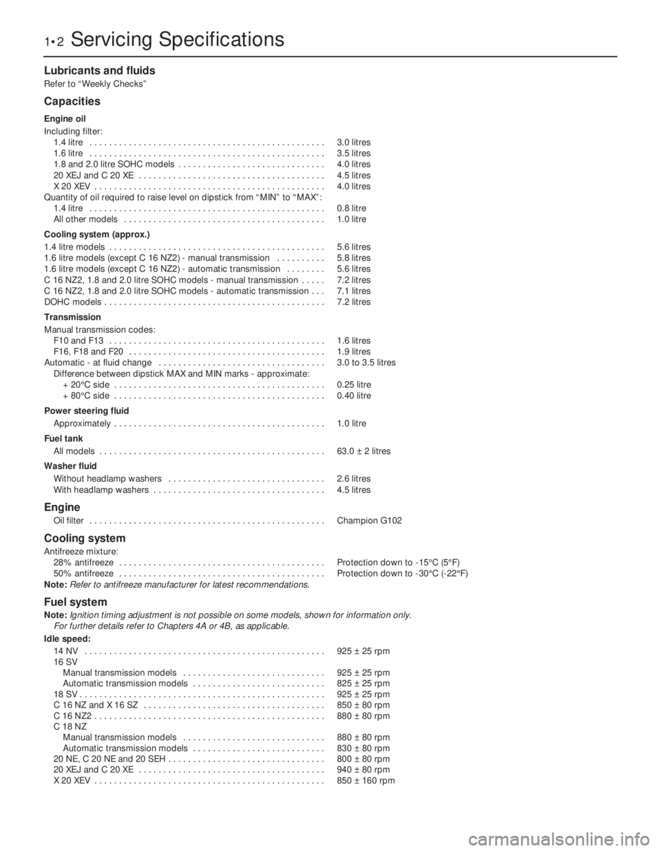
Lubricants and fluids
Refer to “Weekly Checks”
Capacities
Engine oil
Including filter:
1.4 litre . . . . . . . . . . . . . . . . . . . . . . . . . . . . . . . . . . . . . . . . . . . . . . . .3.0 litres
1.6 litre . . . . . . . . . . . . . . . . . . . . . . . . . . . . . . . . . . . . . . . . . . . . . . . .3.5 litres
1.8 and 2.0 litre SOHC models . . . . . . . . . . . . . . . . . . . . . . . . . . . . . .4.0 litres
20 XEJ and C 20 XE . . . . . . . . . . . . . . . . . . . . . . . . . . . . . . . . . . . . . .4.5 litres
X 20 XEV . . . . . . . . . . . . . . . . . . . . . . . . . . . . . . . . . . . . . . . . . . . . . . .4.0 litres
Quantity of oil required to raise level on dipstick from “MIN” to “MAX”:
1.4 litre . . . . . . . . . . . . . . . . . . . . . . . . . . . . . . . . . . . . . . . . . . . . . . . .0.8 litre
All other models . . . . . . . . . . . . . . . . . . . . . . . . . . . . . . . . . . . . . . . . .1.0 litre
Cooling system (approx.)
1.4 litre models . . . . . . . . . . . . . . . . . . . . . . . . . . . . . . . . . . . . . . . . . . . .5.6 litres
1.6 litre models (except C 16 NZ2) - manual transmission . . . . . . . . . .5.8 litres
1.6 litre models (except C 16 NZ2) - automatic transmission . . . . . . . .5.6 litres
C 16 NZ2, 1.8 and 2.0 litre SOHC models - manual transmission . . . . .7.2 litres
C 16 NZ2, 1.8 and 2.0 litre SOHC models - automatic transmission . . .7.1 litres
DOHC models . . . . . . . . . . . . . . . . . . . . . . . . . . . . . . . . . . . . . . . . . . . . .7.2 litres
Transmission
Manual transmission codes:
F10 and F13 . . . . . . . . . . . . . . . . . . . . . . . . . . . . . . . . . . . . . . . . . . . .1.6 litres
F16, F18 and F20 . . . . . . . . . . . . . . . . . . . . . . . . . . . . . . . . . . . . . . . .1.9 litres
Automatic - at fluid change . . . . . . . . . . . . . . . . . . . . . . . . . . . . . . . . . .3.0 to 3.5 litres
Difference between dipstick MAX and MIN marks -approximate:
+ 20°C side . . . . . . . . . . . . . . . . . . . . . . . . . . . . . . . . . . . . . . . . . . .0.25 litre
+ 80°C side . . . . . . . . . . . . . . . . . . . . . . . . . . . . . . . . . . . . . . . . . . .0.40 litre
Power steering fluid
Approximately . . . . . . . . . . . . . . . . . . . . . . . . . . . . . . . . . . . . . . . . . . .1.0 litre
Fuel tank
All models . . . . . . . . . . . . . . . . . . . . . . . . . . . . . . . . . . . . . . . . . . . . . .63.0 ±2 litres
Washer fluid
Without headlamp washers . . . . . . . . . . . . . . . . . . . . . . . . . . . . . . . .2.6 litres
With headlamp washers . . . . . . . . . . . . . . . . . . . . . . . . . . . . . . . . . . .4.5 litres
Engine
Oil filter . . . . . . . . . . . . . . . . . . . . . . . . . . . . . . . . . . . . . . . . . . . . . . . .Champion G102
Cooling system
Antifreeze mixture:
28% antifreeze . . . . . . . . . . . . . . . . . . . . . . . . . . . . . . . . . . . . . . . . . .Protection down to -15°C (5°F)
50% antifreeze . . . . . . . . . . . . . . . . . . . . . . . . . . . . . . . . . . . . . . . . . .Protection down to -30°C (-22°F)
Note:
Refer to antifreeze manufacturer for latest recommendations.
Fuel system
Note:Ignition timing adjustment is not possible on some models, shown for information only.
For further details refer to Chapters 4A or 4B, as applicable.
Idle speed:
14 NV . . . . . . . . . . . . . . . . . . . . . . . . . . . . . . . . . . . . . . . . . . . . . . . . .925 ±25 rpm
16 SV
Manual transmission models . . . . . . . . . . . . . . . . . . . . . . . . . . . . .925 ±25 rpm
Automatic transmission models . . . . . . . . . . . . . . . . . . . . . . . . . . .825 ±25 rpm
18 SV . . . . . . . . . . . . . . . . . . . . . . . . . . . . . . . . . . . . . . . . . . . . . . . . . .925 ±25 rpm
C 16 NZ and X 16 SZ . . . . . . . . . . . . . . . . . . . . . . . . . . . . . . . . . . . . .850 ±80 rpm
C 16 NZ2 . . . . . . . . . . . . . . . . . . . . . . . . . . . . . . . . . . . . . . . . . . . . . . .880 ±80 rpm
C 18 NZ
Manual transmission models . . . . . . . . . . . . . . . . . . . . . . . . . . . . .880 ±80 rpm
Automatic transmission models . . . . . . . . . . . . . . . . . . . . . . . . . . .830 ±80 rpm
20 NE, C 20 NE and 20 SEH . . . . . . . . . . . . . . . . . . . . . . . . . . . . . . . .800 ±80 rpm
20 XEJ and C 20 XE . . . . . . . . . . . . . . . . . . . . . . . . . . . . . . . . . . . . . .940 ±80 rpm
X 20 XEV . . . . . . . . . . . . . . . . . . . . . . . . . . . . . . . . . . . . . . . . . . . . . . .850 ±160 rpm
1•2Servicing Specifications
Page 175 of 525
1•4Maintenance schedule
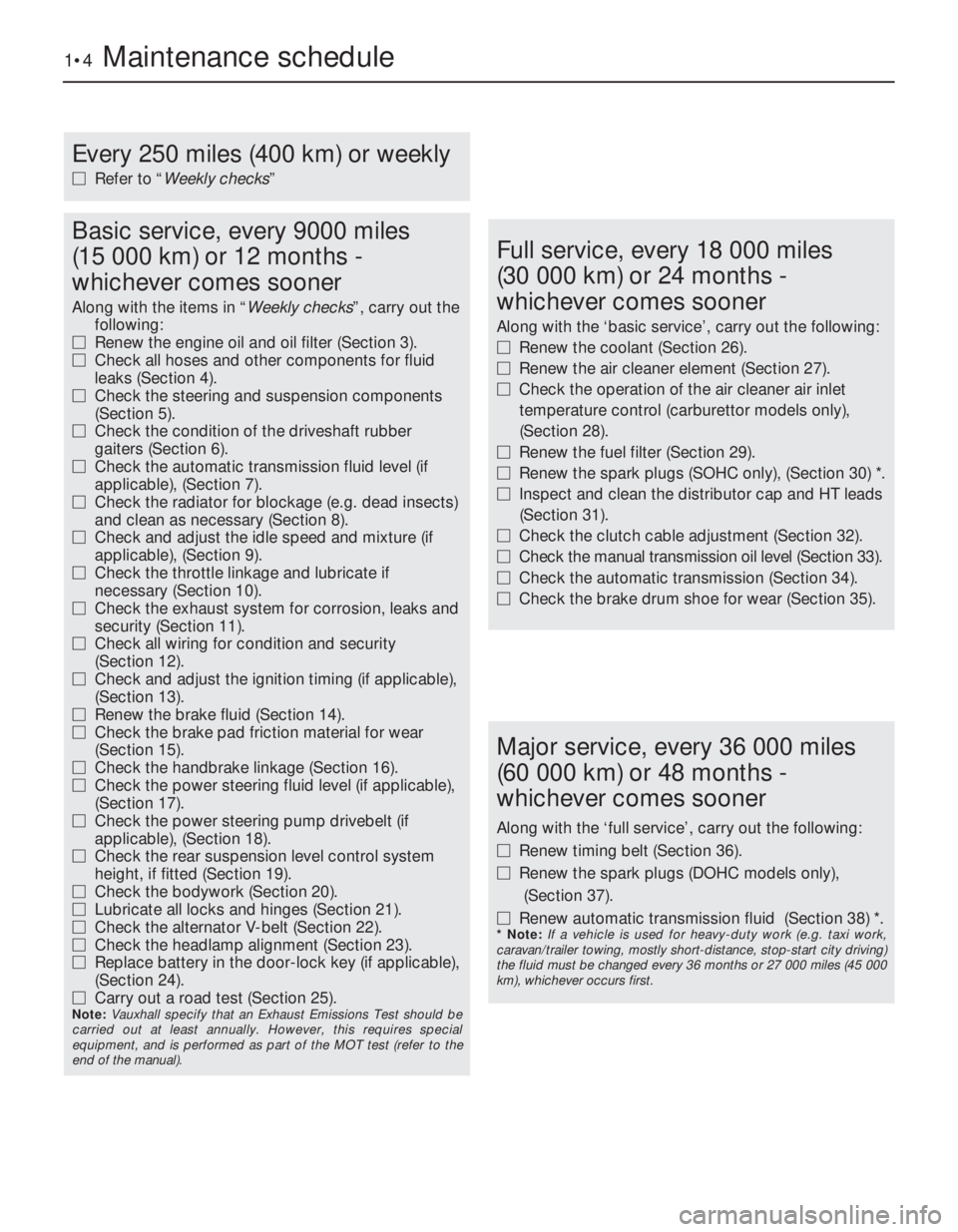
Every 250 miles (400 km) or weekly
MRefer to “Weekly checks”
Basic service, every 9000 miles
(15 000 km) or 12 months -
whichever comes sooner
Along with the items in “Weekly checks”, carry out the
following:
MRenew the engine oil and oil filter (Section 3).
MCheck all hoses and other components for fluid
leaks (Section 4).
MCheck the steering and suspension components
(Section 5).
MCheck the condition of the driveshaft rubber
gaiters (Section 6).
MCheck the automatic transmission fluid level (if
applicable), (Section 7).
MCheck the radiator for blockage (e.g. dead insects)
and clean as necessary (Section 8).
MCheck and adjust the idle speed and mixture (if
applicable), (Section 9).
MCheck the throttle linkage and lubricate if
necessary (Section 10).
MCheck the exhaust system for corrosion, leaks and
security (Section 11).
MCheck all wiring for condition and security
(Section 12).
MCheck and adjust the ignition timing (if applicable),
(Section 13).
MRenew the brake fluid (Section 14).
MCheck the brake pad friction material for wear
(Section 15).
MCheck the handbrake linkage (Section 16).
MCheck the power steering fluid level (if applicable),
(Section 17).
MCheck the power steering pump drivebelt (if
applicable), (Section 18).
MCheck the rear suspension level control system
height, if fitted (Section 19).
MCheck the bodywork (Section 20).
MLubricate all locks and hinges (Section 21).
MCheck the alternator V-belt (Section 22).
MCheck the headlamp alignment (Section 23).
MReplace battery in the door-lock key (if applicable),
(Section 24).
MCarry out a road test (Section 25).
Note: Vauxhall specify that an Exhaust Emissions Test should be
carried out at least annually. However, this requires special
equipment, and is performed as part of the MOT test (refer to the
end of the manual).
Full service, every 18 000 miles
(30 000 km) or 24 months -
whichever comes sooner
Along with the ‘basic service’, carry out the following:
MRenew the coolant (Section 26).
MRenew the air cleaner element (Section 27).
MCheck the operation of the air cleaner air inlet
temperature control (carburettor models only),
(Section 28).
MRenew the fuel filter (Section 29).
MRenew the spark plugs (SOHC only), (Section 30) *.
MInspect and clean the distributor cap and HT leads
(Section 31).
MCheck the clutch cable adjustment (Section 32).
MCheck the manual transmission oil level (Section 33).
MCheck the automatic transmission (Section 34).
MCheck the brake drum shoe for wear (Section 35).
Major service, every 36 000 miles
(60 000 km) or 48 months -
whichever comes sooner
Along with the ‘full service’, carry out the following:
MRenew timing belt (Section 36).
MRenew the spark plugs (DOHC models only),
(Section 37).
MRenew automatic transmission fluid (Section 38) *.
* Note: If a vehicle is used for heavy-duty work (e.g. taxi work,
caravan/trailer towing, mostly short-distance, stop-start city driving)
the fluid must be changed every 36 months or 27 000 miles (45 000
km), whichever occurs first.
Page 176 of 525
Maintenance - component location 1•5
1
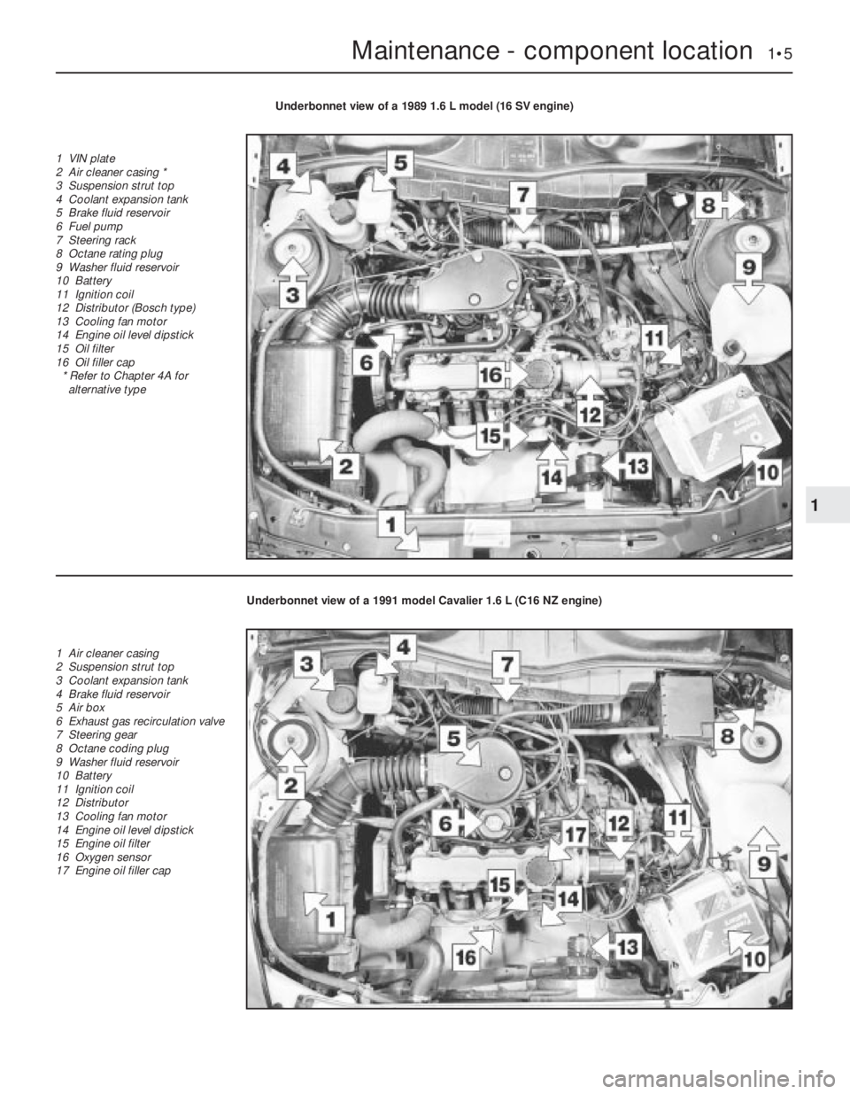
Underbonnet view of a 1989 1.6 L model (16 SV engine)
1 VIN plate
2 Air cleaner casing *
3 Suspension strut top
4 Coolant expansion tank
5 Brake fluid reservoir
6 Fuel pump
7 Steering rack
8 Octane rating plug
9 Washer fluid reservoir
10 Battery
11 Ignition coil
12 Distributor (Bosch type)
13 Cooling fan motor
14 Engine oil level dipstick
15 Oil filter
16 Oil filler cap
* Refer to Chapter 4A for
alternative type
Underbonnet view of a 1991 model Cavalier 1.6 L (C16 NZ engine)
1 Air cleaner casing
2 Suspension strut top
3 Coolant expansion tank
4 Brake fluid reservoir
5 Air box
6 Exhaust gas recirculation valve
7 Steering gear
8 Octane coding plug
9 Washer fluid reservoir
10 Battery
11 Ignition coil
12 Distributor
13 Cooling fan motor
14 Engine oil level dipstick
15 Engine oil filter
16 Oxygen sensor
17 Engine oil filler cap
Page 177 of 525
1•6Maintenance - component location
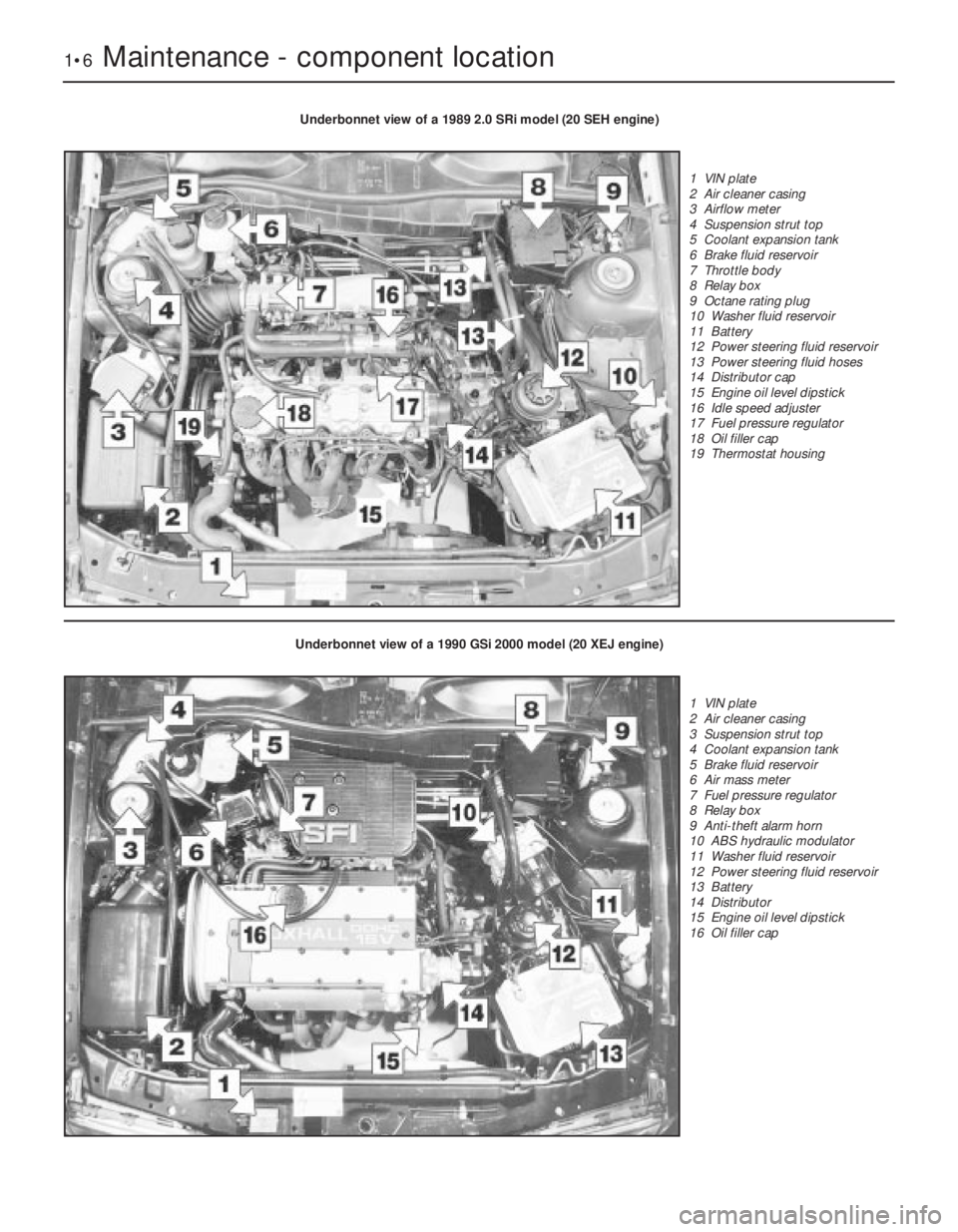
Underbonnet view of a 1989 2.0 SRi model (20 SEH engine)
1 VIN plate
2 Air cleaner casing
3 Airflow meter
4 Suspension strut top
5 Coolant expansion tank
6 Brake fluid reservoir
7 Throttle body
8 Relay box
9 Octane rating plug
10 Washer fluid reservoir
11 Battery
12 Power steering fluid reservoir
13 Power steering fluid hoses
14 Distributor cap
15 Engine oil level dipstick
16 Idle speed adjuster
17 Fuel pressure regulator
18 Oil filler cap
19 Thermostat housing
Underbonnet view of a 1990 GSi 2000 model (20 XEJ engine)
1 VIN plate
2 Air cleaner casing
3 Suspension strut top
4 Coolant expansion tank
5 Brake fluid reservoir
6 Air mass meter
7 Fuel pressure regulator
8 Relay box
9 Anti-theft alarm horn
10 ABS hydraulic modulator
11 Washer fluid reservoir
12 Power steering fluid reservoir
13 Battery
14 Distributor
15 Engine oil level dipstick
16 Oil filler cap
Page 179 of 525

1Introduction
This Chapter is designed to help the home
mechanic maintain his/her vehicle for safety,
economy, long life and peak performance.
The Chapter contains a master maintenance
schedule, followed by Sections dealing specifically
with each task in the schedule. Visual checks,
adjustments, component renewal and other helpful
items are included. Refer to the accompanying
illustrations of the engine compartment and the
underside of the vehicle for the locations of the
various components.
Servicing your vehicle according to the
mileage/time maintenance schedule and the
following Sections will provide a planned
maintenance programme, which should result in a
long and reliable service life. This is a comprehensiveplan, so maintaining some items but not others at
the specified service intervals, will not produce the
same results.
As you service your vehicle, you will
discover that many of the procedures can -
and should - be grouped together, because of
the particular procedure being performed, or
because of the proximity of two otherwise-
unrelated components to one another. For
example, if the vehicle is raised for any
reason, the exhaust can be inspected at the
same time as the suspension and steering
components.
The first step in this maintenance
programme is to prepare yourself before the
actual work begins. Read through all the
Sections relevant to the work to be carried
out, then make a list and gather all the parts
and tools required. If a problem is found, seek
advice from a parts specialist, or a dealer
service department.
2Intensive maintenance
If, from the time the vehicle is new, routine
maintenance schedule is followed closely,
frequent checks made of fluid levels and high-
wear items, as recommended, the engine will
be kept in relatively good running condition.
The need for additional work will be minimised
It is possible that there will be times when
the engine is running poorly due to the lack of
regular maintenance. This is even more likely
if a used vehicle, which has not received
regular and frequent maintenance checks, is
purchased. In such cases, additional work
may need to be carried out, outside of the
regular maintenance intervals.
If engine wear is suspected, a compression
1•8Maintenance - component location
Rear underbody view of a 1990 GSi 2000 model (fully independent rear suspension)
1 Fuel tank securing strap
2 Shock absorber
3 ABS wheel sensor
4 Semi-trailing arm
5 Suspension crossmember
mounting bracing bracket
6 Handbrake cable
7 Suspension crossmember
8 Exhaust expansion box
9 Fuel pump
Maintenance procedures
Page 181 of 525
2Also check the security and condition of all
the engine related pipes and hoses. Ensure
that all cable-ties or securing clips are in
place, and in good condition. Clips that are
broken or missing can lead to chafing of the
hoses, pipes or wiring, which could cause
more serious problems in the future.
3Carefully check the radiator hoses and
heater hoses along their entire length. Renew
any hose that is cracked, swollen or
deteriorated. Cracks will show up better if the
hose is squeezed. Pay close attention to the
hose clips that secure the hoses to the
cooling system components. Hose clips can
pinch and puncture hoses, resulting in cooling
system leaks. It is always beneficial to renew
hose clips whenever possible.
4Inspect all the cooling system components
(hoses, joint faces, etc.) for leaks.
5Where any problems are found on system
components, renew the component or gasket
with reference to Chapter 3.
6Where applicable, inspect the automatic
transmission fluid cooler hoses for leaks or
deterioration.
7With the vehicle raised, inspect the petrol
tank and filler neck for punctures, cracks and
other damage. The connection between the
filler neck and tank is especially critical.
Sometimes a rubber filler neck or connecting
hose will leak due to loose retaining clamps or
deteriorated rubber.
8Carefully check all rubber hoses and metal
fuel lines leading away from the petrol tank.
Check for loose connections, deteriorated
hoses, crimped lines, and other damage. Pay
particular attention to the vent pipes and
hoses, which often loop up around the filler
neck and can become blocked or crimped.
Follow the lines to the front of the vehicle,
carefully inspecting them all the way. Renew
damaged sections as necessary.
9From within the engine compartment,
check the security of all fuel hose attachments
and pipe unions, and inspect the fuel hoses
and vacuum hoses for kinks, chafing and
deterioration.
10Where applicable, check the condition of
the power steering fluid hoses and pipes.5Steering and suspension
check
2
Front suspension and steering
check
1Raise the front of the car, and support on
axle stands (“Jacking and Vehicle Support”).
2Visually inspect the balljoint dust covers
and the steering rack-and-pinion gaiters for
splits, chafing or deterioration. Any wear of
these components will cause loss of lubricant,
together with dirt and water entry, resulting in
rapid wear of the balljoints or steering gear.
3On vehicles with power steering, check the
fluid hoses for chafing or deterioration, and
the pipe and hose unions for fluid leaks. Also
check for signs of fluid leakage under
pressure from the steering gear rubber
gaiters, which would indicate failed fluid seals
within the steering gear.
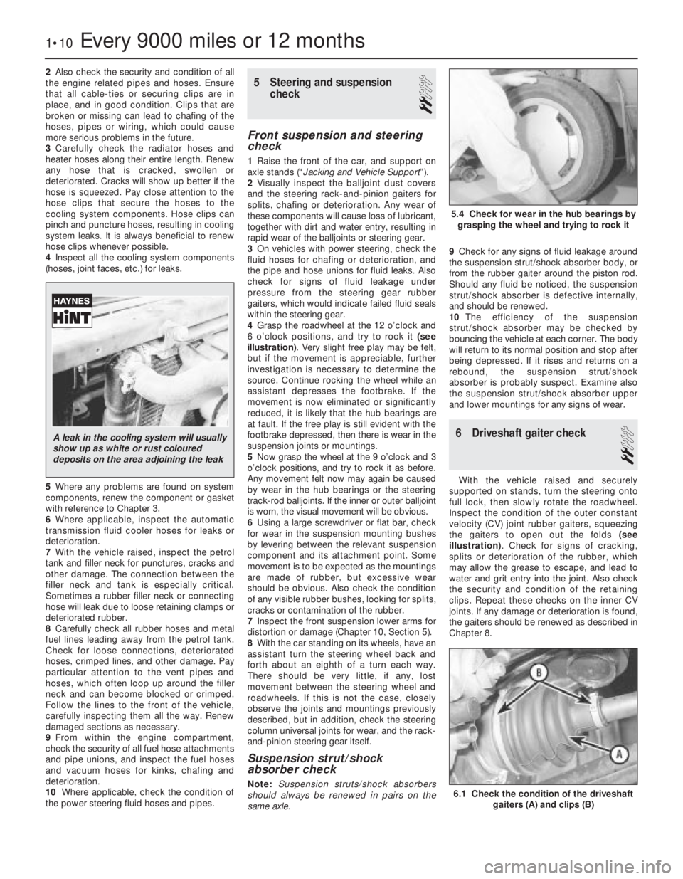
4Grasp the roadwheel at the 12 o’clock and
6 o’clock positions, and try to rock it (see
illustration). Very slight free play may be felt,
but if the movement is appreciable, further
investigation is necessary to determine the
source. Continue rocking the wheel while an
assistant depresses the footbrake. If the
movement is now eliminated or significantly
reduced, it is likely that the hub bearings are
at fault. If the free play is still evident with the
footbrake depressed, then there is wear in the
suspension joints or mountings.
5Now grasp the wheel at the 9 o’clock and 3
o’clock positions, and try to rock it as before.
Any movement felt now may again be caused
by wear in the hub bearings or the steering
track-rod balljoints. If the inner or outer balljoint
is worn, the visual movement will be obvious.
6Using a large screwdriver or flat bar, check
for wear in the suspension mounting bushes
by levering between the relevant suspension
component and its attachment point. Some
movement is to be expected as the mountings
are made of rubber, but excessive wear
should be obvious. Also check the condition
of any visible rubber bushes, looking for splits,
cracks or contamination of the rubber.
7Inspect the front suspension lower arms for
distortion or damage (Chapter 10, Section 5).
8With the car standing on its wheels, have an
assistant turn the steering wheel back and
forth about an eighth of a turn each way.
There should be very little, if any, lost
movement between the steering wheel and
roadwheels. If this is not the case, closely
observe the joints and mountings previously
described, but in addition, check the steering
column universal joints for wear, and the rack-
and-pinion steering gear itself.
Suspension strut/shock
absorber check
Note:Suspension struts/shock absorbers
should always be renewed in pairs on the
same axle.9Check for any signs of fluid leakage around
the suspension strut/shock absorber body, or
from the rubber gaiter around the piston rod.
Should any fluid be noticed, the suspension
strut/shock absorber is defective internally,
and should be renewed.
10The efficiency of the suspension
strut/shock absorber may be checked by
bouncing the vehicle at each corner. The body
will return to its normal position and stop after
being depressed. If it rises and returns on a
rebound, the suspension strut/shock
absorber is probably suspect. Examine also
the suspension strut/shock absorber upper
and lower mountings for any signs of wear.
6Driveshaft gaiter check
2
With the vehicle raised and securely
supported on stands, turn the steering onto
full lock, then slowly rotate the roadwheel.
Inspect the condition of the outer constant
velocity (CV) joint rubber gaiters, squeezing
the gaiters to open out the folds (see
illustration). Check for signs of cracking,
splits or deterioration of the rubber, which
may allow the grease to escape, and lead to
water and grit entry into the joint. Also check
the security and condition of the retaining
clips. Repeat these checks on the inner CV
joints. If any damage or deterioration is found,
the gaiters should be renewed as described in
Chapter 8.
1•10Every 9000 miles or 12 months
6.1 Check the condition of the driveshaft
gaiters (A) and clips (B)
5.4 Check for wear in the hub bearings by
grasping the wheel and trying to rock it
A leak in the cooling system will usually
show up as white or rust coloured
deposits on the area adjoining the leak