1988 OPEL CALIBRA fuse
[x] Cancel search: fusePage 159 of 525
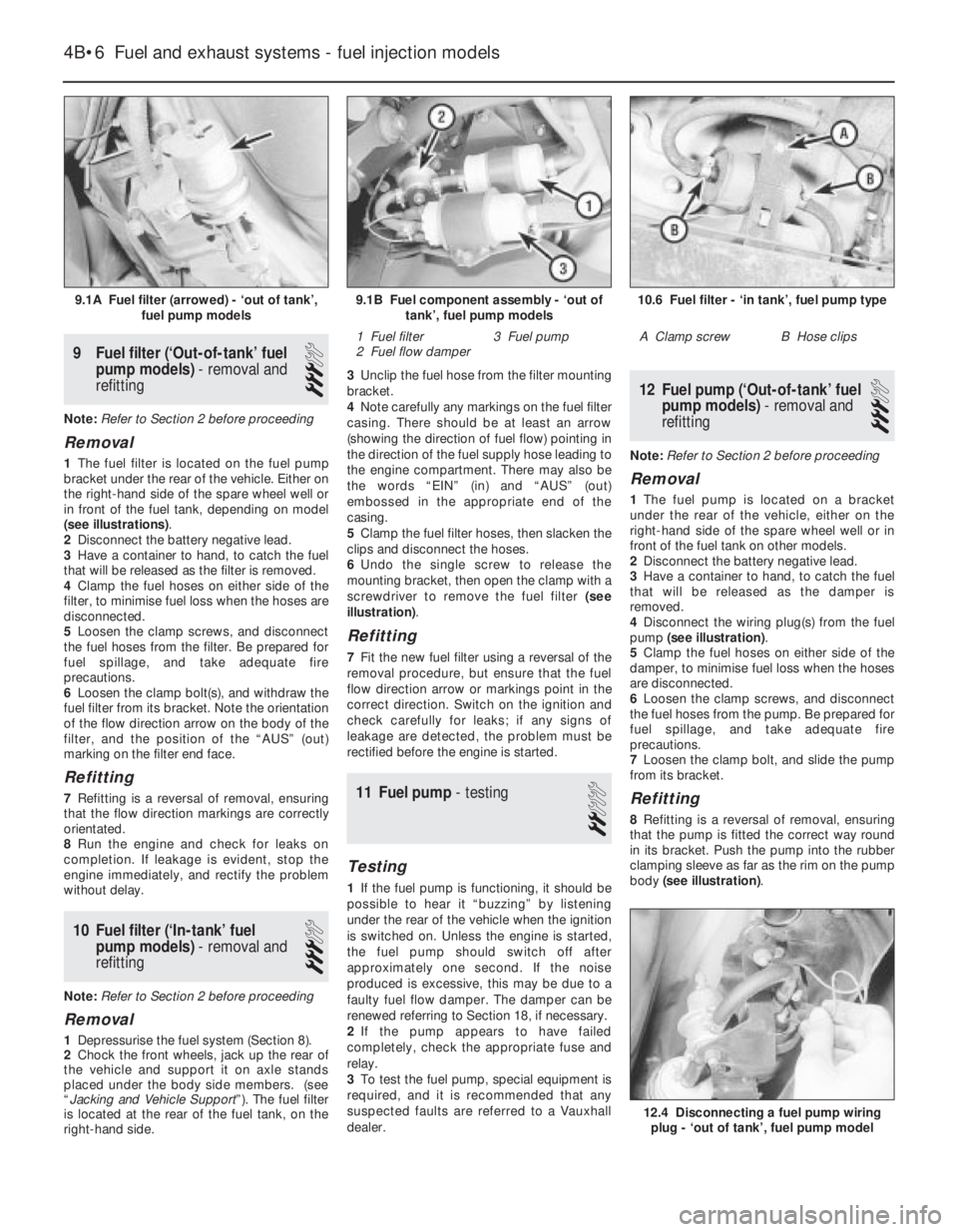
9Fuel filter (‘Out-of-tank’ fuel
pump models) - removal and
refitting
3
Note: Refer to Section 2 before proceeding
Removal
1The fuel filter is located on the fuel pump
bracket under the rear of the vehicle. Either on
the right-hand side of the spare wheel well or
in front of the fuel tank, depending on model
(see illustrations).
2Disconnect the battery negative lead.
3Have a container to hand, to catch the fuel
that will be released as the filter is removed.
4Clamp the fuel hoses on either side of the
filter, to minimise fuel loss when the hoses are
disconnected.
5Loosen the clamp screws, and disconnect
the fuel hoses from the filter. Be prepared for
fuel spillage, and take adequate fire
precautions.
6Loosen the clamp bolt(s), and withdraw the
fuel filter from its bracket. Note the orientation
of the flow direction arrow on the body of the
filter, and the position of the “AUS” (out)
marking on the filter end face.
Refitting
7Refitting is a reversal of removal, ensuring
that the flow direction markings are correctly
orientated.
8Run the engine and check for leaks on
completion. If leakage is evident, stop the
engine immediately, and rectify the problem
without delay.
10Fuel filter (‘In-tank’ fuel
pump models) - removal and
refitting
3
Note: Refer to Section 2 before proceeding
Removal
1Depressurise the fuel system (Section 8).
2Chock the front wheels, jack up the rear of
the vehicle and support it on axle stands
placed under the body side members. (see
“Jacking and Vehicle Support”). The fuel filter
is located at the rear of the fuel tank, on the
right-hand side.3Unclip the fuel hose from the filter mounting
bracket.
4Note carefully any markings on the fuel filter
casing. There should be at least an arrow
(showing the direction of fuel flow) pointing in
the direction of the fuel supply hose leading to
the engine compartment. There may also be
the words “EIN” (in) and “AUS” (out)
embossed in the appropriate end of the
casing.
5Clamp the fuel filter hoses, then slacken the
clips and disconnect the hoses.
6Undo the single screw to release the
mounting bracket, then open the clamp with a
screwdriver to remove the fuel filter (see
illustration).
Refitting
7Fit the new fuel filter using a reversal of the
removal procedure, but ensure that the fuel
flow direction arrow or markings point in the
correct direction. Switch on the ignition and
check carefully for leaks; if any signs of
leakage are detected, the problem must be
rectified before the engine is started.
11Fuel pump - testing
2
Testing
1If the fuel pump is functioning, it should be
possible to hear it “buzzing” by listening
under the rear of the vehicle when the ignition
is switched on. Unless the engine is started,
the fuel pump should switch off after
approximately one second. If the noise
produced is excessive, this may be due to a
faulty fuel flow damper. The damper can be
renewed referring to Section 18, if necessary.
2If the pump appears to have failed
completely, check the appropriate fuse and
relay.
3To test the fuel pump, special equipment is
required, and it is recommended that any
suspected faults are referred to a Vauxhall
dealer.
12Fuel pump (‘Out-of-tank’ fuel
pump models) - removal and
refitting
3
Note: Refer to Section 2 before proceeding
Removal
1The fuel pump is located on a bracket
under the rear of the vehicle, either on the
right-hand side of the spare wheel well or in
front of the fuel tank on other models.
2Disconnect the battery negative lead.
3Have a container to hand, to catch the fuel
that will be released as the damper is
removed.
4Disconnect the wiring plug(s) from the fuel
pump (see illustration).
5Clamp the fuel hoses on either side of the
damper, to minimise fuel loss when the hoses
are disconnected.
6Loosen the clamp screws, and disconnect
the fuel hoses from the pump. Be prepared for
fuel spillage, and take adequate fire
precautions.
7Loosen the clamp bolt, and slide the pump
from its bracket.
Refitting
8Refitting is a reversal of removal, ensuring
that the pump is fitted the correct way round
in its bracket. Push the pump into the rubber
clamping sleeve as far as the rim on the pump
body (see illustration).
4B•6Fuel and exhaust systems - fuel injection models
9.1A Fuel filter (arrowed) - ‘out of tank’,
fuel pump models10.6 Fuel filter - ‘in tank’, fuel pump type
A Clamp screwB Hose clips
12.4 Disconnecting a fuel pump wiring
plug - ‘out of tank’, fuel pump model
9.1B Fuel component assembly - ‘out of
tank’, fuel pump models
1 Fuel filter
2 Fuel flow damper3 Fuel pump
Page 243 of 525

REF•4General Repair Procedures
Whenever servicing, repair or overhaul work
is carried out on the car or its components, it is
necessary to observe the following procedures
and instructions. This will assist in carrying out
the operation efficiently and to a professional
standard of workmanship.
Joint mating faces and gaskets
When separating components at their
mating faces, never insert screwdrivers or
similar implements into the joint between the
faces in order to prise them apart. This can
cause severe damage which results in oil
leaks, coolant leaks, etc upon reassembly.
Separation is usually achieved by tapping
along the joint with a soft-faced hammer in
order to break the seal. However, note that this
method may not be suitable where dowels are
used for component location.
Where a gasket is used between the mating
faces of two components, ensure that it is
renewed on reassembly, and fit it dry unless
otherwise stated in the repair procedure. Make
sure that the mating faces are clean and dry,
with all traces of old gasket removed. When
cleaning a joint face, use a tool which is not
likely to score or damage the face, and remove
any burrs or nicks with an oilstone or fine file.
Make sure that tapped holes are cleaned
with a pipe cleaner, and keep them free of
jointing compound, if this is being used, unless
specifically instructed otherwise.
Ensure that all orifices, channels or pipes
are clear, and blow through them, preferably
using compressed air.
Oil seals
Oil seals can be removed by levering them
out with a wide flat-bladed screwdriver or
similar implement. Alternatively, a number of
self-tapping screws may be screwed into the
seal, and these used as a purchase for pliers
or some similar device in order to pull the seal
free.
Whenever an oil seal is removed from its
working location, either individually or as part
of an assembly, it should be renewed.
The very fine sealing lip of the seal is easily
damaged, and will not seal if the surface it
contacts is not completely clean and free from
scratches, nicks or grooves.
Protect the lips of the seal from any surface
which may damage them in the course of
fitting. Use tape or a conical sleeve where
possible. Lubricate the seal lips with oil before
fitting and, on dual-lipped seals, fill the space
between the lips with grease.
Unless otherwise stated, oil seals must be
fitted with their sealing lips toward the
lubricant to be sealed.
Use a tubular drift or block of wood of the
appropriate size to install the seal and, if the
seal housing is shouldered, drive the seal
down to the shoulder. If the seal housing is
unshouldered, the seal should be fitted with its
face flush with the housing top face (unless
otherwise instructed).
Screw threads and fastenings
Seized nuts, bolts and screws are quite a
common occurrence where corrosion has set
in, and the use of penetrating oil or releasing
fluid will often overcome this problem if the
offending item is soaked for a while before
attempting to release it. The use of an impact
driver may also provide a means of releasing
such stubborn fastening devices, when used
in conjunction with the appropriate
screwdriver bit or socket. If none of these
methods works, it may be necessary to resort
to the careful application of heat, or the use of
a hacksaw or nut splitter device.
Studs are usually removed by locking two
nuts together on the threaded part, and then
using a spanner on the lower nut to unscrew
the stud. Studs or bolts which have broken off
below the surface of the component in which
they are mounted can sometimes be removed
using a proprietary stud extractor. Always
ensure that a blind tapped hole is completely
free from oil, grease, water or other fluid
before installing the bolt or stud. Failure to do
this could cause the housing to crack due to
the hydraulic action of the bolt or stud as it is
screwed in.
When tightening a castellated nut to accept
a split pin, tighten the nut to the specified
torque, where applicable, and then tighten
further to the next split pin hole. Never slacken
the nut to align the split pin hole, unless stated
in the repair procedure.
When checking or retightening a nut or bolt
to a specified torque setting, slacken the nut
or bolt by a quarter of a turn, and then
retighten to the specified setting. However,
this should not be attempted where angular
tightening has been used.
For some screw fastenings, notably cylinder
head bolts or nuts, torque wrench settings are
no longer specified for the latter stages of
tightening, “angle-tightening” being called up
instead. Typically, a fairly low torque wrench
setting will be applied to the bolts/nuts in
the correct sequence, followed by one or
more stages of tightening through specified
angles.
Locknuts, locktabs and washers
Any fastening which will rotate against a
component or housing in the course of
tightening should always have a washer
between it and the relevant component or
housing.
Spring or split washers should always be
renewed when they are used to lock a critical
component such as a big-end bearing
retaining bolt or nut. Locktabs which are
folded over to retain a nut or bolt should
always be renewed.
Self-locking nuts can be re-used in non-
critical areas, providing resistance can be felt
when the locking portion passes over the bolt
or stud thread. However, it should be noted
that self-locking stiffnuts tend to lose theireffectiveness after long periods of use, and in
such cases should be renewed as a matter of
course.
Split pins must always be replaced with new
ones of the correct size for the hole.
When thread-locking compound is found on
the threads of a fastener which is to be re-
used, it should be cleaned off with a wire
brush and solvent, and fresh compound
applied on reassembly.
Special tools
Some repair procedures in this manual
entail the use of special tools such as a press,
two or three-legged pullers, spring
compressors, etc. Wherever possible, suitable
readily-available alternatives to the
manufacturer’s special tools are described,
and are shown in use. Unless you are highly-
skilled and have a thorough understanding of
the procedures described, never attempt to
bypass the use of any special tool when the
procedure described specifies its use. Not
only is there a very great risk of personal injury,
but expensive damage could be caused to the
components involved.
Environmental considerations
When disposing of used engine oil, brake
fluid, antifreeze, etc, give due consideration to
any detrimental environmental effects. Do not,
for instance, pour any of the above liquids
down drains into the general sewage system,
or onto the ground to soak away. Many local
council refuse tips provide a facility for waste
oil disposal, as do some garages. If none of
these facilities are available, consult your local
Environmental Health Department for further
advice.
With the universal tightening-up of
legislation regarding the emission of
environmentally-harmful substances from
motor vehicles, most current vehicles have
tamperproof devices fitted to the main
adjustment points of the fuel system. These
devices are primarily designed to prevent
unqualified persons from adjusting the fuel/air
mixture, with the chance of a consequent
increase in toxic emissions. If such devices are
encountered during servicing or overhaul, they
should, wherever possible, be renewed or
refitted in accordance with the vehicle
manufacturer’s requirements or current
legislation.
Note: It is
antisocial and
illegal to dump
oil down the
drain. To find
the location of
your local oil
recycling
bank, call this
number free.
Page 251 of 525
Engine
m mEngine fails to rotate when attempting to start
m mEngine rotates, but will not start
m mEngine difficult to start when cold
m mEngine difficult to start when hot
m mStarter motor noisy or excessively rough in engagement
m mEngine starts, but stops immediately
m mEngine idles erratically
m mEngine misfires at idle speed
m mEngine misfires throughout the driving speed range
m mEngine hesitates on acceleration
m mEngine stalls
m mEngine lacks power
m mEngine backfires
m mOil pressure warning light illuminated with engine running
m mEngine runs-on after switching off
m mEngine noises
Cooling system
m
mOverheating
m mOvercooling
m mExternal coolant leakage
m mInternal coolant leakage
m mCorrosion
Fuel and exhaust systems
m
mExcessive fuel consumption
m mFuel leakage and/or fuel odour
m mExcessive noise or fumes from exhaust system
Clutch
m
mPedal travels to floor - no pressure or very little resistance
m mClutch fails to disengage (unable to select gears)
m mClutch slips (engine speed increases, with no increase in vehicle
speed)
m mJudder as clutch is engaged
m mNoise when depressing or releasing clutch pedal
Manual transmission
m
mNoisy in neutral with engine running
m mNoisy in one particular gear
m mDifficulty engaging gears
m mJumps out of gear
m mVibration
m mLubricant leaks
Automatic transmission
m
mFluid leakage
m mTransmission fluid brown, or has burned smell
m mGeneral gear selection problems
m mTransmission will not downshift (kickdown) with accelerator fully
depressed
m mEngine will not start in any gear, or starts in gears other than Park
or Neutral
m mTransmission slips, shifts roughly, is noisy, or has no drive in
forward or reverse gears
Driveshafts
m mClicking or knocking noise on turns (at slow speed on full-lock)
m mVibration when accelerating or decelerating
Braking system
m
mVehicle pulls to one side under braking
m mNoise (grinding or high-pitched squeal) when brakes applied
m mExcessive brake pedal travel
m mBrake pedal feels spongy when depressed
m mExcessive brake pedal effort required to stop vehicle
m mJudder felt through brake pedal or steering wheel when braking
m mBrakes binding
m mRear wheels locking under normal braking
Suspension and steering systems
m
mVehicle pulls to one side
m mWheel wobble and vibration
m mExcessive pitching and/or rolling around corners, or during
braking
m mWandering or general instability
m mExcessively stiff steering
m mExcessive play in steering
m mLack of power assistance
m mTyre wear excessive
Electrical system
m
mBattery will not hold a charge for more than a few days
m mIgnition/no-charge warning light remains illuminated with engine
running
m mIgnition/no-charge warning light fails to come on
m mLights inoperative
m mInstrument readings inaccurate or erratic
m mHorn inoperative, or unsatisfactory in operation
m mWindscreen/tailgate wipers inoperative, or unsatisfactory in
operation
m mWindscreen/tailgate washers inoperative, or unsatisfactory in
operation
m mElectric windows inoperative, or unsatisfactory in operation
m mCentral locking system inoperative, or unsatisfactory in operation
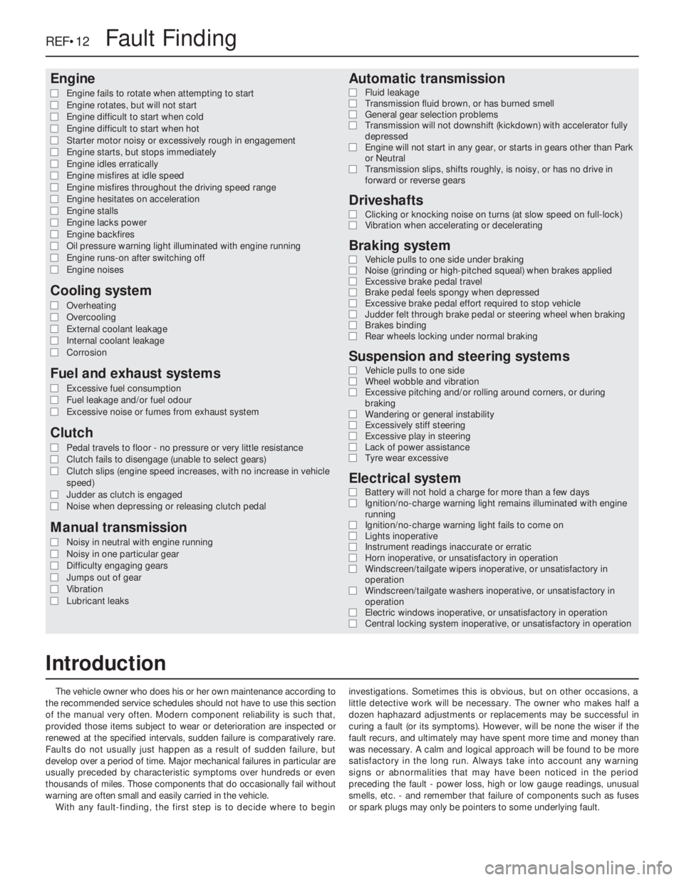
The vehicle owner who does his or her own maintenance according to
the recommended service schedules should not have to use this section
of the manual very often. Modern component reliability is such that,
provided those items subject to wear or deterioration are inspected or
renewed at the specified intervals, sudden failure is comparatively rare.
Faults do not usually just happen as a result of sudden failure, but
develop over a period of time. Major mechanical failures in particular are
usually preceded by characteristic symptoms over hundreds or even
thousands of miles. Those components that do occasionally fail without
warning are often small and easily carried in the vehicle.
With any fault-finding, the first step is to decide where to begininvestigations. Sometimes this is obvious, but on other occasions, a
little detective work will be necessary. The owner who makes half a
dozen haphazard adjustments or replacements may be successful in
curing a fault (or its symptoms). However, will be none the wiser if the
fault recurs, and ultimately may have spent more time and money than
was necessary. A calm and logical approach will be found to be more
satisfactory in the long run. Always take into account any warning
signs or abnormalities that may have been noticed in the period
preceding the fault - power loss, high or low gauge readings, unusual
smells, etc. - and remember that failure of components such as fuses
or spark plugs may only be pointers to some underlying fault.
REF•12Fault Finding
Introduction
Page 255 of 525
Note:Due to the complexity of the automatic transmission, it is difficult
for the home mechanic to properly diagnose and service this unit. For
problems other than the following, the vehicle should be taken to a
dealer service department or automatic transmission specialist. Do not
be too hasty in removing the transmission if a fault is suspected, as
most of the testing is carried out with the unit still fitted.
Fluid leakage
MAutomatic transmission fluid is usually dark in colour. Fluid leaks
should not be confused with engine oil, which can easily be blown
onto the transmission by airflow.
MTo determine the source of a leak, first remove all built-up dirt and
grime from the transmission housing and surrounding areas using
a degreasing agent, or by steam-cleaning. Drive the vehicle at low
speed, so airflow will not blow the leak far from its source. Raise
and support the vehicle, and determine where the leak is coming
from. The following are common areas of leakage:
a)Fluid pan or “sump” (Chapter 1 and 7B).
b)Dipstick tube (Chapter 1 and 7B).
c)Transmission-to-fluid cooler pipes/unions (Chapter 7B).
Transmission fluid brown, or has burned smell
MTransmission fluid level low, or fluid in need of renewal (Chapter 1).
General gear selection problems
MChapter 7B deals with checking and adjusting the selector cable
on automatic transmissions. The following are common problems
that may be caused by a poorly adjusted cable:a)Engine starting in gears other than Park or Neutral.
b)Indicator panel indicating a gear other than the one actually being
used.
c)Vehicle moves when in Park or Neutral.
d)Poor gear shift quality or erratic gear changes.
MRefer to Chapter 7B for the selector cable adjustment procedure.
Transmission will not downshift (kickdown) with
accelerator pedal fully depressed
MLow transmission fluid level (Chapter 1).
MIncorrect selector cable adjustment (Chapter 7B).
Engine will not start in any gear, or starts in gears
other than Park or Neutral
MIncorrect starter/inhibitor switch adjustment (Chapter 7B).
MIncorrect selector cable adjustment (Chapter 7B).
Transmission slips, shifts roughly, is noisy, or has
no drive in forward or reverse gears
MThere are many probable causes for the above problems, but the
home mechanic should be concerned with only one possibility -
fluid level. Before taking the vehicle to a dealer or transmission
specialist, check the fluid level and condition of the fluid as
described in Chapter 1. Correct the fluid level as necessary, or
change the fluid and filter if needed. If the problem persists,
professional help will be necessary.
Clicking or knocking noise on turns (at slow speed
on full-lock)
MLack of constant velocity joint lubricant, possibly due to damaged
gaiter (Chapter 8).
MWorn outer constant velocity joint (Chapter 8).
Vibration when accelerating or decelerating
MWorn inner constant velocity joint (Chapter 8).
MBent or distorted driveshaft (Chapter 8).
REF•16Fault Finding
Automatic transmission
Driveshafts
Noisy in neutral with engine running
MInput shaft bearings worn (noise apparent with clutch pedal
released, but not when depressed), (Chapter 7A).*
MClutch release bearing worn (noise apparent with clutch pedal
depressed, possibly less when released), (Chapter 6).
Noisy in one particular gear
MWorn, damaged or chipped gear teeth (Chapter 7A).*
Difficulty engaging gears
MClutch fault (Chapter 6).
MWorn or damaged gear linkage (Chapter 7A).
MIncorrectly adjusted gear linkage (Chapter 7A).
MWorn synchroniser units (Chapter 7A).*
Jumps out of gear
MWorn or damaged gear linkage (Chapter 7A).
MIncorrectly adjusted gear linkage (Chapter 7A).MWorn synchroniser units (Chapter 7A).*
MWorn selector forks (Chapter 7A).*
Vibration
MLack of oil (Chapter 1).
MWorn bearings (Chapter 7A).*
Lubricant leaks
MLeaking differential output oil seal (Chapter 7A).
MLeaking housing joint (Chapter 7A).*
MLeaking input shaft oil seal (Chapter 7A).*
* Although the corrective action necessary to remedy the symptoms
described is beyond the scope of the home mechanic, the above
information should be helpful in isolating the cause of the condition.
This should enable the owner can communicate clearly with a
professional mechanic.
Manual transmission
Page 257 of 525
Note:For problems associated with the starting system, refer to the
faults listed under “Engine” earlier in this Section.
Battery will not hold a charge for more than a few
days
MBattery defective internally (Chapter 5).
MBattery terminal connections loose or corroded (Chapter 1).
MAuxiliary drivebelt worn or incorrectly adjusted (Chapter 1).
MAlternator not charging at correct output (Chapter 5).
MAlternator or voltage regulator faulty (Chapter 5).
MShort-circuit causing continual battery drain (Chapters 5 and 12).
Ignition/no-charge warning light remains
illuminated with engine running
MAuxiliary drivebelt broken, worn, or incorrectly adjusted (Chapter 1).
MAlternator brushes worn, sticking, or dirty (Chapter 5).
MAlternator brush springs weak or broken (Chapter 5).
MInternal fault in alternator or voltage regulator (Chapter 5).
MBroken, disconnected, or loose wiring in charging circuit
(Chapter 5).
Ignition/no-charge warning light fails to come on
MWarning light bulb blown (Chapter 12).
MBroken, disconnected, or loose wiring in warning light circuit
(Chapter 12).
MAlternator faulty (Chapter 5).
Lights inoperative
MBulb blown (Chapter 12).
MCorrosion of bulb or bulbholder contacts (Chapter 12).
MBlown fuse (Chapter 12).
MFaulty relay (Chapter 12).
MBroken, loose, or disconnected wiring (Chapter 12).
MFaulty switch (Chapter 12).
Instrument readings inaccurate or erratic
Instrument readings increase with engine speed
MFaulty voltage regulator (Chapter 12).
Fuel or temperature gauges give no reading
MFaulty gauge sender unit (Chapters 3, 4A and 4B).
MWiring open-circuit (Chapter 12).
MFaulty gauge (Chapter 12).
Fuel or temperature gauges give continuous maximum
reading
MFaulty gauge sender unit (Chapters 3, 4A and 4B).
MWiring short-circuit (Chapter 12).
MFaulty gauge (Chapter 12). MIncorrect front wheel alignment (Chapter 10).
MSteering rack or column bent or damaged (Chapter 10).
Excessive play in steering
MWorn steering column intermediate shaft universal joint
(Chapter 10).
MWorn steering track rod end balljoints (Chapters 1 and 10).
MWorn rack-and-pinion steering gear (Chapter 10).
MWorn steering or suspension joints, bushes or components
(Chapters 1 and 10).
Lack of power assistance
MBroken or incorrectly adjusted auxiliary drivebelt (Chapter 1).
MIncorrect power steering fluid level (Chapter 1).
MRestriction in power steering fluid hoses (Chapter 1).
MFaulty power steering pump (Chapter 10).
MFaulty rack-and-pinion steering gear (Chapter 10).
Tyre wear excessive
Tyres worn on inside or outside edges
MTyres under-inflated (wear on both edges), (Chapter 1).
MIncorrect camber or castor angles (wear on one edge only),
(Chapter 10).
MWorn steering or suspension joints, bushes or components
(Chapters 1 and 10).
MExcessively hard cornering.
MAccident damage.
Tyre treads exhibit feathered edges
MIncorrect toe setting (Chapter 10).
Tyres worn in centre of tread
MTyres over-inflated (Chapter 1).
Tyres worn on inside and outside edges
MTyres under-inflated (Chapter 1).
Tyres worn unevenly
MTyres/wheels out of balance (Chapter 1).
MExcessive wheel or tyre run-out (Chapter 1).
MWorn shock absorbers (Chapters 1 and 10).
MFaulty tyre (Chapter 1).
REF•18Fault Finding
Electrical system
Suspension and steering (continued)
Page 258 of 525
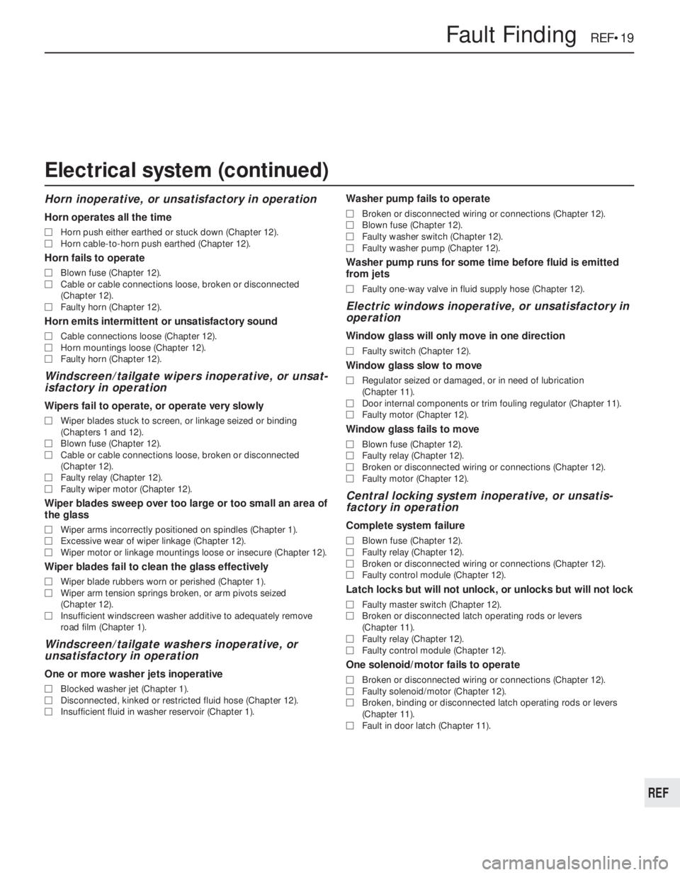
Horn inoperative, or unsatisfactory in operation
Horn operates all the time
MHorn push either earthed or stuck down (Chapter 12).
MHorn cable-to-horn push earthed (Chapter 12).
Horn fails to operate
MBlown fuse (Chapter 12).
MCable or cable connections loose, broken or disconnected
(Chapter 12).
MFaulty horn (Chapter 12).
Horn emits intermittent or unsatisfactory sound
MCable connections loose (Chapter 12).
MHorn mountings loose (Chapter 12).
MFaulty horn (Chapter 12).
Windscreen/tailgate wipers inoperative, or unsat-
isfactory in operation
Wipers fail to operate, or operate very slowly
MWiper blades stuck to screen, or linkage seized or binding
(Chapters 1 and 12).
MBlown fuse (Chapter 12).
MCable or cable connections loose, broken or disconnected
(Chapter 12).
MFaulty relay (Chapter 12).
MFaulty wiper motor (Chapter 12).
Wiper blades sweep over too large or too small an area of
the glass
MWiper arms incorrectly positioned on spindles (Chapter 1).
MExcessive wear of wiper linkage (Chapter 12).
MWiper motor or linkage mountings loose or insecure (Chapter 12).
Wiper blades fail to clean the glass effectively
MWiper blade rubbers worn or perished (Chapter 1).
MWiper arm tension springs broken, or arm pivots seized
(Chapter 12).
MInsufficient windscreen washer additive to adequately remove
road film (Chapter 1).
Windscreen/tailgate washers inoperative, or
unsatisfactory in operation
One or more washer jets inoperative
MBlocked washer jet (Chapter 1).
MDisconnected, kinked or restricted fluid hose (Chapter 12).
MInsufficient fluid in washer reservoir (Chapter 1).
Washer pump fails to operate
MBroken or disconnected wiring or connections (Chapter 12).
MBlown fuse (Chapter 12).
MFaulty washer switch (Chapter 12).
MFaulty washer pump (Chapter 12).
Washer pump runs for some time before fluid is emitted
from jets
MFaulty one-way valve in fluid supply hose (Chapter 12).
Electric windows inoperative, or unsatisfactory in
operation
Window glass will only move in one direction
MFaulty switch (Chapter 12).
Window glass slow to move
MRegulator seized or damaged, or in need of lubrication
(Chapter 11).
MDoor internal components or trim fouling regulator (Chapter 11).
MFaulty motor (Chapter 12).
Window glass fails to move
MBlown fuse (Chapter 12).
MFaulty relay (Chapter 12).
MBroken or disconnected wiring or connections (Chapter 12).
MFaulty motor (Chapter 12).
Central locking system inoperative, or unsatis-
factory in operation
Complete system failure
MBlown fuse (Chapter 12).
MFaulty relay (Chapter 12).
MBroken or disconnected wiring or connections (Chapter 12).
MFaulty control module (Chapter 12).
Latch locks but will not unlock, or unlocks but will not lock
MFaulty master switch (Chapter 12).
MBroken or disconnected latch operating rods or levers
(Chapter 11).
MFaulty relay (Chapter 12).
MFaulty control module (Chapter 12).
One solenoid/motor fails to operate
MBroken or disconnected wiring or connections (Chapter 12).
MFaulty solenoid/motor (Chapter 12).
MBroken, binding or disconnected latch operating rods or levers
(Chapter 11).
MFault in door latch (Chapter 11).
Fault Finding REF•19
REF
Electrical system (continued)
Page 261 of 525

REF•22Glossary of Technical Terms
EEGR valveA valve used to introduce exhaust
gases into the intake air stream.
Electronic control unit (ECU)A computer
which controls (for instance) ignition and fuel
injection systems, or an anti-lock braking
system. For more information refer to the
Haynes Automotive Electrical and Electronic
Systems Manual.
Electronic Fuel Injection (EFI)A computer
controlled fuel system that distributes fuel
through an injector located in each intake port
of the engine.
Emergency brakeA braking system,
independent of the main hydraulic system,
that can be used to slow or stop the vehicle if
the primary brakes fail, or to hold the vehicle
stationary even though the brake pedal isn’t
depressed. It usually consists of a hand lever
that actuates either front or rear brakes
mechanically through a series of cables and
linkages. Also known as a handbrake or
parking brake.
EndfloatThe amount of lengthwise
movement between two parts. As applied to a
crankshaft, the distance that the crankshaft
can move forward and back in the cylinder
block.
Engine management system (EMS)A
computer controlled system which manages
the fuel injection and the ignition systems in
an integrated fashion.
Exhaust manifoldA part with several
passages through which exhaust gases leave
the engine combustion chambers and enter
the exhaust pipe.
FFan clutchA viscous (fluid) drive coupling
device which permits variable engine fan
speeds in relation to engine speeds.Feeler bladeA thin strip or blade of hardened
steel, ground to an exact thickness, used to
check or measure clearances between parts.
Firing orderThe order in which the engine
cylinders fire, or deliver their power strokes,
beginning with the number one cylinder.
Flywheel A heavy spinning wheel in which
energy is absorbed and stored by means of
momentum. On cars, the flywheel is attached
to the crankshaft to smooth out firing
impulses.
Free playThe amount of travel before any
action takes place. The “looseness” in a
linkage, or an assembly of parts, between the
initial application of force and actual
movement. For example, the distance the
brake pedal moves before the pistons in the
master cylinder are actuated.
FuseAn electrical device which protects a
circuit against accidental overload. The typical
fuse contains a soft piece of metal which is
calibrated to melt at a predetermined current
flow (expressed as amps) and break the
circuit.
Fusible linkA circuit protection device
consisting of a conductor surrounded by
heat-resistant insulation. The conductor is
smaller than the wire it protects, so it acts as
the weakest link in the circuit. Unlike a blown
fuse, a failed fusible link must frequently be
cut from the wire for replacement.
GGapThe distance the spark must travel in
jumping from the centre electrode to the sideelectrode in a spark plug. Also refers to the
spacing between the points in a contact
breaker assembly in a conventional points-
type ignition, or to the distance between the
reluctor or rotor and the pickup coil in an
electronic ignition.
GasketAny thin, soft material - usually cork,
cardboard, asbestos or soft metal - installed
between two metal surfaces to ensure a good
seal. For instance, the cylinder head gasket
seals the joint between the block and the
cylinder head.
GaugeAn instrument panel display used to
monitor engine conditions. A gauge with a
movable pointer on a dial or a fixed scale is an
analogue gauge. A gauge with a numerical
readout is called a digital gauge.
HHalfshaftA rotating shaft that transmits
power from the final drive unit to a drive
wheel, usually when referring to a live rear
axle.
Harmonic balancerA device designed to
reduce torsion or twisting vibration in the
crankshaft. May be incorporated in the
crankshaft pulley. Also known as a vibration
damper.
HoneAn abrasive tool for correcting small
irregularities or differences in diameter in an
engine cylinder, brake cylinder, etc.
Hydraulic tappetA tappet that utilises
hydraulic pressure from the engine’s
lubrication system to maintain zero clearance
(constant contact with both camshaft and
valve stem). Automatically adjusts to variation
in valve stem length. Hydraulic tappets also
reduce valve noise.
IIgnition timingThe moment at which the
spark plug fires, usually expressed in the
number of crankshaft degrees before the
piston reaches the top of its stroke.
Inlet manifoldA tube or housing with
passages through which flows the air-fuel
mixture (carburettor vehicles and vehicles with
throttle body injection) or air only (port fuel-
injected vehicles) to the port openings in the
cylinder head.
Exhaust manifold
Feeler blade
Adjusting spark plug gap
Gasket
EGR valve
Page 265 of 525
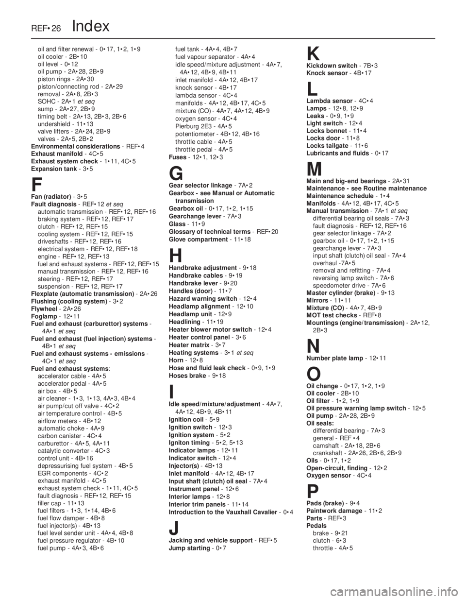
oil and filter renewal - 0•17, 1•2, 1•9
oil cooler - 2B•10
oil level - 0•12
oil pump - 2A•28, 2B•9
piston rings - 2A•30
piston/connecting rod - 2A•29
removal - 2A•8, 2B•3
SOHC - 2A•1 et seq
sump - 2A•27, 2B•9
timing belt - 2A•13, 2B•3, 2B•6
undershield - 11•13
valve lifters - 2A•24, 2B•9
valves - 2A•5, 2B•2
Environmental considerations- REF•4
Exhaust manifold- 4C•5
Exhaust system check- 1•11, 4C•5
Expansion tank- 3•5
FFan (radiator)- 3•5
Fault diagnosis- REF•12 et seq
automatic transmission - REF•12, REF•16
braking system - REF•12, REF•17
clutch - REF•12, REF•15
cooling system - REF•12, REF•15
driveshafts - REF•12, REF•16
electrical system - REF•12, REF•18
engine - REF•12, REF•13
fuel and exhaust systems - REF•12, REF•15
manual transmission - REF•12, REF•16
steering - REF•12, REF•17
suspension - REF•12, REF•17
Flexplate (automatic transmission)- 2A•26
Flushing (cooling system)- 3•2
Flywheel- 2A•26
Foglamp- 12•11
Fuel and exhaust (carburettor) systems-
4A•1 et seq
Fuel and exhaust (fuel injection) systems-
4B•1 et seq
Fuel and exhaust systems - emissions-
4C•1 et seq
Fuel and exhaust systems:
accelerator cable - 4A•5
accelerator pedal - 4A•5
air box - 4B•5
air cleaner - 1•3, 1•13, 4A•3, 4B•4
air pump/cut off valve - 4C•2
air temperature control - 4B•5
airflow meters - 4B•12
automatic choke - 4A•9
carbon canister - 4C•4
carburettor - 4A•5, 4A•11
catalytic converter - 4C•3
control unit - 4B•16
depressurising fuel system - 4B•5
EGR components - 4C•2
exhaust manifold - 4C•5
exhaust system check - 1•11, 4C•5
fault diagnosis - REF•12, REF•15
filler cap - 11•13
fuel filters - 1•3, 1•14, 4B•6
fuel flow damper - 4B•8
fuel injector(s) - 4B•13
fuel level sender unit - 4A•4, 4B•8
fuel pressure regulator - 4B•10
fuel pump - 4A•3, 4B•6fuel tank - 4A•4, 4B•7
fuel vapour separator - 4A•4
idle speed/mixture adjustment - 4A•7,
4A•12, 4B•9, 4B•11
inlet manifold - 4A•12, 4B•17
knock sensor - 4B•17
lambda sensor - 4C•4
manifolds - 4A•12, 4B•17, 4C•5
mixture (CO) - 4A•7, 4A•12, 4B•9
oxygen sensor - 4C•4
Pierburg 2E3 - 4A•5
potentiometer - 4B•12, 4B•16
throttle cable - 4A•5
throttle pedal - 4A•5
Fuses- 12•1, 12•3
GGear selector linkage- 7A•2
Gearbox - see Manual or Automatic
transmission
Gearbox oil- 0•17, 1•2, 1•15
Gearchange lever- 7A•3
Glass- 11•9
Glossary of technical terms- REF•20
Glove compartment- 11•18
HHandbrake adjustment- 9•18
Handbrake cables- 9•19
Handbrake lever- 9•20
Handles (door)- 11•7
Hazard warning switch- 12•4
Headlamp alignment- 12•10
Headlamp unit- 12•9
Headlining- 11•19
Heater blower motor switch- 12•4
Heater control panel- 3•6
Heater matrix- 3•7
Heating systems- 3•1 et seq
Horn- 12•8
Hose and fluid leak check- 0•9, 1•9
Hoses brake- 9•18
IIdle speed/mixture/adjustment- 4A•7,
4A•12, 4B•9, 4B•11
Ignition coil- 5•9
Ignition switch- 12•3
Ignition system- 5•2
Igniton timing- 5•2, 5•13
Indicator lamps- 12•11
Indicator switch- 12•4
Injector(s)- 4B•13
Inlet manifold- 4A•12, 4B•17
Input shaft (clutch) oil seal- 7A•4
Instrument panel- 12•6
Interior lamps- 12•8
Interior trim panels- 11•14
Introduction to the Vauxhall Cavalier- 0•4
JJacking and vehicle support- REF•5
Jump starting- 0•7
KKickdown switch - 7B•3
Knock sensor- 4B•17
LLambda sensor- 4C•4
Lamps- 12•8, 12•9
Leaks- 0•9, 1•9
Light switch- 12•4
Locks bonnet- 11•4
Locks door- 11•8
Locks tailgate- 11•6
Lubricants and fluids- 0•17
MMain and big-end bearings- 2A•31
Maintenance - see Routine maintenance
Maintenance schedule- 1•4
Manifolds- 4A•12, 4B•17, 4C•5
Manual transmission- 7A•1 et seq
differential bearing oil seals - 7A•3
fault diagnosis - REF•12, REF•16
gear selector linkage - 7A•2
gearbox oil - 0•17, 1•2, 1•15
gearchange lever - 7A•3
input shaft (clutch) oil seal - 7A•4
overhaul -7A•5
removal and refitting - 7A•4
reversing lamp switch - 7A•6
speedometer drive - 7A•6
Master cylinder (brake)- 9•13
Mirrors- 11•11
Mixture (CO)- 4A•7, 4B•9
MOT test checks- REF•8
Mountings (engine/transmission)- 2A•12,
2B•3
NNumber plate lamp- 12•11
OOil change- 0•17, 1•2, 1•9
Oil cooler- 2B•10
Oil filter- 1•2, 1•9
Oil pressure warning lamp switch- 12•5
Oil pump- 2A•28, 2B•9
Oil seals:
differential bearing - 7A•3
general - REF •4
camshaft - 2A•18, 2B•6
crankshaft - 2A•26, 2B•6, 2B•9
Oils- 0•17, 1•2
Open-circuit, finding - 12•2
Oxygen sensor- 4C•4
PPads (brake)- 9•4
Paintwork damage- 11•2
Parts- REF•3
Pedals
brake - 9•21
clutch - 6•3
throttle - 4A•5
REF•26Index