1988 OPEL CALIBRA driver seat adjustment
[x] Cancel search: driver seat adjustmentPage 162 of 525
4B
4Clamp the fuel hoses on either side of the
damper, to minimise fuel loss when the hoses
are disconnected.
5Loosen the clamp screws, and disconnect
the fuel hoses from the damper. Be prepared
for fuel spillage, and take adequate fire
precautions.
6Unscrew the securing nut, and withdraw
the damper from the bracket.
Refitting
7Refitting is a reversal of removal.
8Run the engine and check for leaks on
completion. If leakage is evident; stop the
engine immediately, and rectify the problem
without delay.
19Throttle cable - removal,
refitting and adjustment
3
Removal
1This procedure is basically the same as
described in Chapter 4A, but note the
following.
2Not all models are fitted with an air box.
Ignore references to it, if not applicable.
3For “carburettor” substitute “throttle body”,
and note that the cable bracket is bolted to
the inlet manifold.
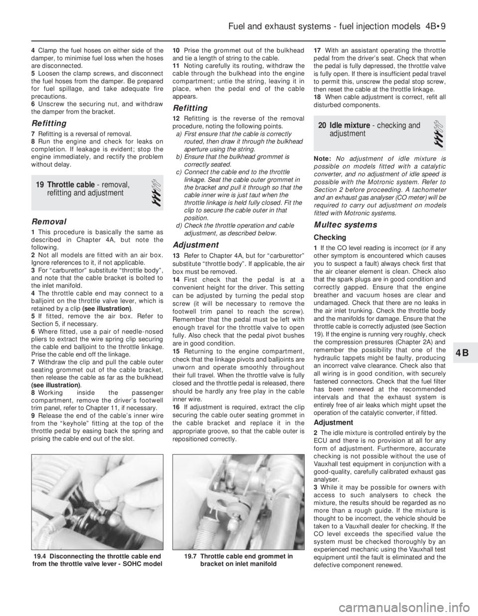
4The throttle cable end may connect to a
balljoint on the throttle valve lever, which is
retained by a clip (see illustration).
5If fitted, remove the air box. Refer to
Section 5, if necessary.
6Where fitted, use a pair of needle-nosed
pliers to extract the wire spring clip securing
the cable end balljoint to the throttle linkage.
Prise the cable end off the linkage.
7Withdraw the clip and pull the cable outer
seating grommet out of the cable bracket,
then release the cable as far as the bulkhead
(see illustration).
8Working inside the passenger
compartment, remove the driver’s footwell
trim panel, refer to Chapter 11, if necessary.
9Release the end of the cable’s inner wire
from the “keyhole” fitting at the top of the
throttle pedal by easing back the spring and
prising the cable end out of the slot.10Prise the grommet out of the bulkhead
and tie a length of string to the cable.
11Noting carefully its routing, withdraw the
cable through the bulkhead into the engine
compartment; untie the string, leaving it in
place, when the pedal end of the cable
appears.
Refitting
12Refitting is the reverse of the removal
procedure, noting the following points.
a)First ensure that the cable is correctly
routed, then draw it through the bulkhead
aperture using the string.
b)Ensure that the bulkhead grommet is
correctly seated.
c)Connect the cable end to the throttle
linkage. Seat the cable outer grommet in
the bracket and pull it through so that the
cable inner wire is just taut when the
throttle linkage is held fully closed. Fit the
clip to secure the cable outer in that
position.
d)Check the throttle operation and cable
adjustment, as described below.
Adjustment
13Refer to Chapter 4A, but for “carburettor”
substitute “throttle body”. If applicable, the air
box must be removed.
14First check that the pedal is at a
convenient height for the driver. This setting
can be adjusted by turning the pedal stop
screw (it will be necessary to remove the
footwell trim panel to reach the screw).
Remember that the pedal must be left with
enough travel for the throttle valve to open
fully. Also check that the pedal pivot bushes
are in good condition.
15Returning to the engine compartment,
check that the linkage pivots and balljoints are
unworn and operate smoothly throughout
their full travel. When the throttle valve is fully
closed and the throttle pedal is released, there
should be hardly any free play in the cable
inner wire.
16If adjustment is required, extract the clip
securing the cable outer seating grommet in
the cable bracket and replace it in the
appropriate groove, so that the cable outer is
repositioned correctly.17With an assistant operating the throttle
pedal from the driver’s seat. Check that when
the pedal is fully depressed, the throttle valve
is fully open. If there is insufficient pedal travel
to permit this, unscrew the pedal stop screw,
then reset the cable at the throttle linkage.
18When cable adjustment is correct, refit all
disturbed components.
20Idle mixture - checking and
adjustment
3
Note: No adjustment of idle mixture is
possible on models fitted with a catalytic
converter, and no adjustment of idle speed is
possible with the Motronic system. Refer to
Section 2 before proceeding. A tachometer
and an exhaust gas analyser (CO meter) will be
required to carry out adjustment on models
fitted with Motronic systems.
Multec systems
Checking
1If the CO level reading is incorrect (or if any
other symptom is encountered which causes
you to suspect a fault) always check first that
the air cleaner element is clean. Check also
that the spark plugs are in good condition and
correctly gapped. Ensure that the engine
breather and vacuum hoses are clear and
undamaged. Check that there are no leaks in
the air inlet trunking. Check the throttle body
and the manifolds for damage. Ensure that the
throttle cable is correctly adjusted (see Section
19). If the engine is running very roughly, check
the compression pressures (Chapter 2A) and
remember the possibility that one of the
hydraulic tappets might be faulty, producing
an incorrect valve clearance. Check also that
all wiring is in good condition, with securely
fastened connectors. Check that the fuel filter
has been renewed at the recommended
intervals and that the exhaust system is
entirely free of air leaks which might upset the
operation of the catalytic converter, if fitted.
Adjustment
2The idle mixture is controlled entirely by the
ECU and there is no provision at all for any
form of adjustment. Furthermore, accurate
checking is not possible without the use of
Vauxhall test equipment in conjunction with a
good-quality, carefully calibrated exhaust gas
analyser.
3While it may be possible for owners with
access to such analysers to check the
mixture, the results should be regarded as no
more than a rough guide. If the mixture is
thought to be incorrect, the vehicle should be
taken to a Vauxhall dealer for checking. If the
CO level exceeds the specified value the
system must be checked thoroughly by an
experienced mechanic using the Vauxhall test
equipment until the fault is eliminated and the
defective component renewed.
Fuel and exhaust systems - fuel injection models 4B•9
19.7 Throttle cable end grommet in
bracket on inlet manifold19.4 Disconnecting the throttle cable end
from the throttle valve lever - SOHC model
Page 169 of 525
b)Check the throttle cable operation and
adjustment (see above).
c)When reconnecting the vacuum hoses
and pipes, ensure that they are connected
to the front unions as shown in the
accompanying photograph.
d)As no fuel vapour trap is fitted, it is
essential that the manifold absolute
pressure sensor vacuum hose is routed
so that it falls steadily from the sensor to
the throttle body. This precaution will
prevent any fuel droplets being trapped in
the sensor or hose and allowing them to
drain into the inlet port.
e)Ensure that the fuel hoses are correctly
reconnected; the feed hose is on the
injector end of the throttle body.
f)Switch on the ignition and check for signs
of fuel leaks from all disturbed unions; if
any signs of leakage are detected, the
problem must be rectified before the
engine is started.
33Idle air control stepper
motor - removal and refitting
3
Removal
1Remove the air box (see Section 5).
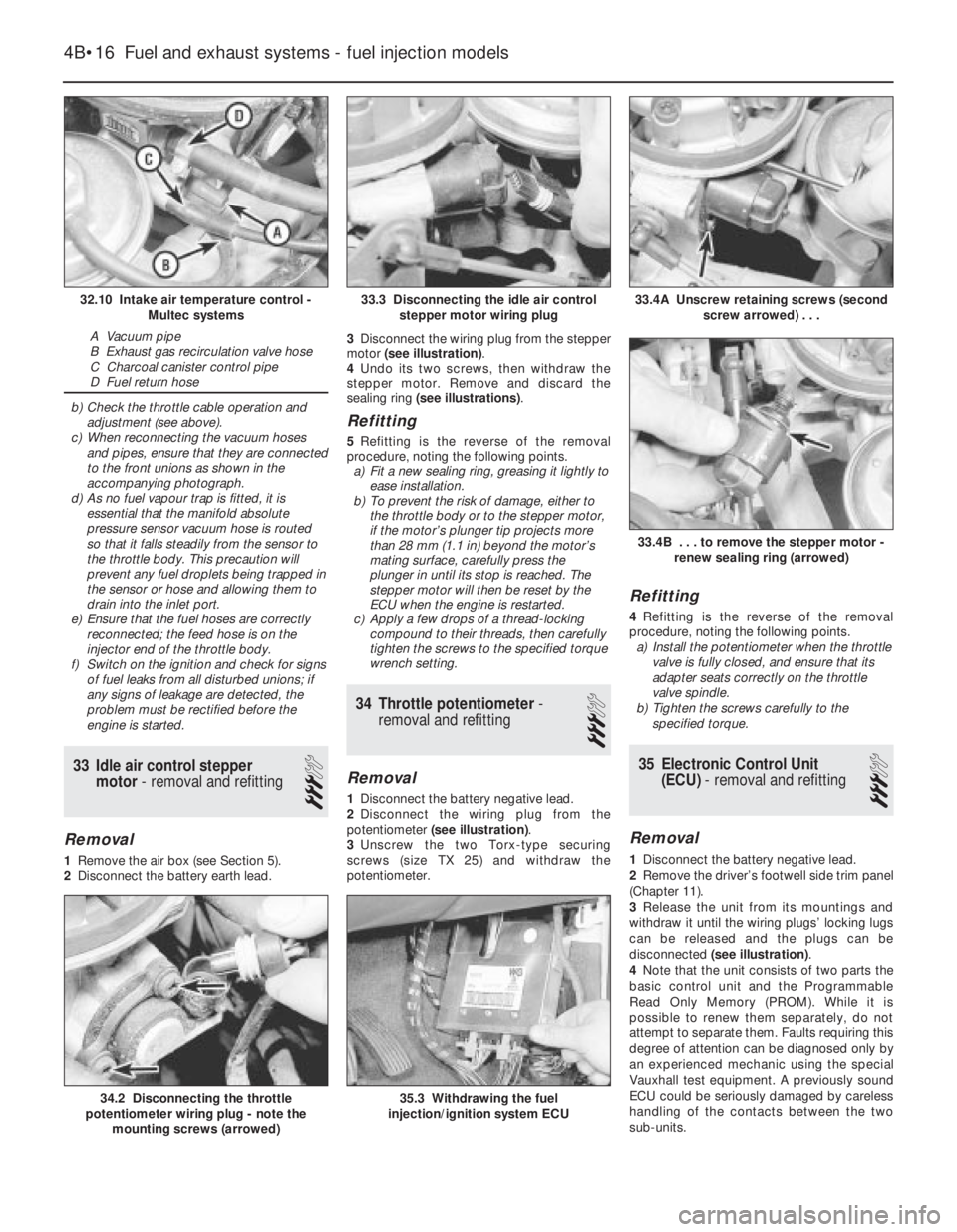
2Disconnect the battery earth lead.3Disconnect the wiring plug from the stepper
motor (see illustration).
4Undo its two screws, then withdraw the
stepper motor. Remove and discard the
sealing ring (see illustrations).
Refitting
5Refitting is the reverse of the removal
procedure, noting the following points.
a)Fit a new sealing ring, greasing it lightly to
ease installation.
b)To prevent the risk of damage, either to
the throttle body or to the stepper motor,
if the motor’s plunger tip projects more
than 28 mm (1.1 in) beyond the motor’s
mating surface, carefully press the
plunger in until its stop is reached. The
stepper motor will then be reset by the
ECU when the engine is restarted.
c)Apply a few drops of a thread-locking
compound to their threads, then carefully
tighten the screws to the specified torque
wrench setting.
34Throttle potentiometer -
removal and refitting
3
Removal
1Disconnect the battery negative lead.
2Disconnect the wiring plug from the
potentiometer (see illustration).
3Unscrew the two Torx-type securing
screws (size TX 25) and withdraw the
potentiometer.
Refitting
4Refitting is the reverse of the removal
procedure, noting the following points.
a)Install the potentiometer when the throttle
valve is fully closed, and ensure that its
adapter seats correctly on the throttle
valve spindle.
b)Tighten the screws carefully to the
specified torque.
35Electronic Control Unit
(ECU) - removal and refitting
3
Removal
1Disconnect the battery negative lead.
2Remove the driver’s footwell side trim panel
(Chapter 11).
3Release the unit from its mountings and
withdraw it until the wiring plugs’ locking lugs
can be released and the plugs can be
disconnected (see illustration).
4Note that the unit consists of two parts the
basic control unit and the Programmable
Read Only Memory (PROM). While it is
possible to renew them separately, do not
attempt to separate them. Faults requiring this
degree of attention can be diagnosed only by
an experienced mechanic using the special
Vauxhall test equipment. A previously sound
ECU could be seriously damaged by careless
handling of the contacts between the two
sub-units.
4B•16Fuel and exhaust systems - fuel injection models
32.10 Intake air temperature control -
Multec systems
A Vacuum pipe
B Exhaust gas recirculation valve hose
C Charcoal canister control pipe
D Fuel return hose
33.4A Unscrew retaining screws (second
screw arrowed) . . .
35.3 Withdrawing the fuel
injection/ignition system ECU34.2 Disconnecting the throttle
potentiometer wiring plug - note the
mounting screws (arrowed)
33.4B . . . to remove the stepper motor -
renew sealing ring (arrowed)
33.3 Disconnecting the idle air control
stepper motor wiring plug
Page 182 of 525
At the same time, check the general
condition of the CV joints themselves by first
holding the driveshaft and attempting to
rotate the wheel. Repeat this check by holding
the inner joint and attempting to rotate the
driveshaft. Any appreciable movement
indicates wear in the joints, wear in the
driveshaft splines, or a loose driveshaft
retaining nut.
7Automatic transmission fluid
level check
2
Note: The transmission fluid level can be
checked either when it is cold (only below
35ºC (100ºF) outside temperature) or when it is
fully warmed up to normal operating
temperature (after driving for a distance of
approximately 12 miles/20 km). Since the fluid
level must be checked with the engine
running, ensure that the vehicle is parked on
level ground with the handbrake firmly applied
before leaving the driver’s seat. Be careful to
keep loose clothing, long hair, etc., well clear
of hot or moving components when working
under the bonnet
Transmission cold
1Park the vehicle on level ground and apply
the handbrake firmly. With the engine running
at no more than idle speed and your foot
firmly on the brake pedal, move the selector
lever through all positions, ending in position
“P”. Allow the engine to idle for one minute,
then check the level within two minutes.
2With the engine still idling and position “P”
still selected, open the bonnet and withdraw
the transmission dipstick from the filler tube
located in the front of the transmission casing,
at the left-hand end of the engine.
3Note the fluid’s condition (see below), then
wipe clean the dipstick using a clean,
non-fluffy rag, insert it fully back into the tube
and withdraw it again.
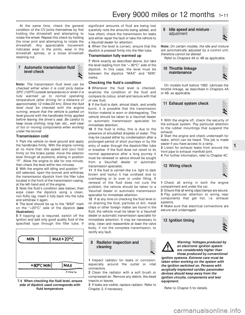
4The level should be up to the “MAX” mark
on the “+20°C” side of the dipstick (see
illustration).
5If topping-up is required, switch off the
ignition and add only good quality fluid of the
specified type through the filler tube. Ifsignificant amounts of fluid are being lost
(carefully note the amounts being added, and
how often), check the transmission for leaks
and either repair the fault or take the vehicle to
a Vauxhall dealer for attention.
6When the level is correct, ensure that the
dipstick is pressed firmly into the filler tube.
Transmission fully warmed up
7Work exactly as described above, but take
the level reading from the “+ 80°C” side of the
dipstick. In this case, the level must be
between the dipstick “MAX” and “MIN”
marks.
Checking the fluid’s condition
8Whenever the fluid level is checked,
examine the condition of the fluid and
compare its colour, smell and texture with that
of new fluid.
9If the fluid is dark, almost black, and smells
burnt, it is possible that the transmission
friction material is worn or disintegrating. The
vehicle should be taken to a Vauxhall dealer
or automatic transmission specialist for
immediate attention.
10If the fluid is milky, this is due to the
presence of emulsified droplets of water. This
may be caused either by condensation after a
prolonged period of short journeys or by the
entry of water through the dipstick/filler tube
or breather. If the fluid does not revert to its
normal appearance after a long journey it
must be renewed or advice should be sought
from a Vauxhall dealer or automatic
transmission specialist.
11If the fluid is varnish-like (i.e. light to dark
brown and tacky) it has oxidised due to
overheating or to over or under filling. If
renewal of the fluid does not cure the
problem, the vehicle should be taken to a
Vauxhall dealer or automatic transmission
specialist for immediate attention.
12If at any time on checking the fluid level or
on draining the fluid, particles of dirt, metal
chips or other foreign matter are found in the
fluid, the vehicle must be taken to a Vauxhall
dealer or automatic transmission specialist for
immediate attention. It may be necessary to
strip, clean and reassemble at least the valve
body, if not the complete transmission, to
rectify any fault.
8Radiator inspection and
cleaning
1
1Inspect radiator for leaks or corrosion,
especially around the outlet or inlet
connectors.
2Clean the radiator with a soft brush or
compressed air. Remove any debris, like dead
insects or leaves.
3If leaks are visible, replace radiator. Refer to
Chapter 3, if necessary.
9Idle speed and mixture -
adjustment
2
Note: On certain models, the idle and mixture
are automatically adjusted by a control unit,
therefore cannot be altered.
Refer to Chapters 4A or 4B as applicable.
10Throttle linkage
maintenance
2
On models built before 1992, lubricate the
throttle linkage, as described in Chapters 4A
or 4B, as applicable.
11Exhaust system check
2
1With the engine off, check the security of
the exhaust system. Pay particular attention
to the rubber mountings that suspend the
exhaust.
2Start the engine and check underneath for
leaks, which can be heard. This job is made
easier if you have access to a ramp.
3Listen for exhaust leaks from around the
front pipe to exhaust manifold joint.
4For further information, refer to Chapter 4C
12Wiring check
1
1Check all wiring in both the engine
compartment and under the car.
2Ensure that all wiring clips/clamps are secure.
3Pay particular attention to wiring near
components that get hot, i.e. exhaust
systems.
4Make sure that electrical connections are
secure and undamaged.
13Ignition timing
3
Refer to Chapter 5 for details.
Every 9000 miles or 12 months 1•11
7.4 When checking the fluid level, ensure
side of dipstick used corresponds with
fluid temperature
1
Warning: Voltages produced by
an electronic ignition system
are considerably higher than
those produced by conventional
ignition systems. Extreme care must be
taken when working on the system with
the ignition switched on. Persons with
surgically implanted cardiac pacemaker
devices should keep away from the
ignition circuits, components and test
equipment.
Page 193 of 525
48Turn the crankshaft clockwise until the
TDC marks on the camshaft sprockets are
aligned with the notches in the camshaft
cover, and check that the crankshaft pulley
TDC mark is aligned with the pointer on the
rear timing belt cover.
49Proceed as described in paragraphs 30 to
34 inclusive.
5Timing belt, with automatic
adjuster- removal, refitting
and adjustment
3
Removal
1The operations are essentially the same as
described in Section 4, except that the
tensioner pulley incorporates an automatic
adjuster that simplifies the procedure as
follows.
2To release the belt tension before removal,
unscrew the timing belt tensioner pulley
securing bolt slightly then, with a large
screwdriver (or similar tool) inserted in the slot
on the tensioner arm, turn the tensioner arm
until the timing belt is slack. Tighten the
securing bolt slightly to hold the tensioner in
this position.
Refitting
3To refit the timing belt, first ensure that the
coolant pump is correctly positioned by
checking that the lug on the coolant pump
flange is aligned with the corresponding lug
on the cylinder block. If this is not the case,
slacken the coolant pump mounting bolts
slightly and move the pump accordingly.
Tighten the bolts to the specified torque on
completion (see Chapter 3).
4Refit the timing belt as described in Section 4,
then tension it as follows.
Adjustment
5Slacken the tensioner pulley securing bolt
and move the tensioner arm anti-clockwise,
until the tensioner pointer lies at its stop.
Tighten the tensioner pulley securing bolt to
hold the tensioner in this position.
6Turn the crankshaft through two complete
revolutions in the normal direction of rotation
and check that with the crankshaft pulley TDC
mark aligned with the pointer on the rear
timing belt cover, the TDC marks on the
camshaft sprockets are still aligned with the
notches in the camshaft cover.
7Slacken the tensioner pulley securing bolt
once again and move the tensioner arm
clockwise, until the tensioner pointer is
aligned with the notch in the tensioner. In the
first few hours of operation a new belt will be
subjected to ‘settling-in’, (known as the
running-in procedure). If you are refitting a
used belt (one that has been ‘run-in’), align the
pointer to approximately 4 mm to the left of
the notch, refer to Section 14 in Chapter 2A.
Tighten the tensioner pulley securing bolt
securely. Turn the crankshaft through onecomplete revolution in the normal direction of
rotation and check that the crankshaft and
camshaft timing marks still align, then refit the
remainder of the components as described in
Section 4.
8With the timing belt adjustment set in this
way, correct tension will always be maintained
by the automatic tensioner and no further
checking or adjustment will be necessary.
6Camshaft front oil seal-
removal and refitting
3
Note: A new timing belt should be used on
refitting
Removal
1The camshaft front oil seals may be
renewed with the engine in the vehicle without
removing the camshafts as follows.
2Remove the timing belt and the relevant
camshaft sprocket(s), as described in Section 4.
3Punch or drill a small hole in the centre of
the now-exposed oil seal. Screw in a
self-tapping screw, and pull on the screw with
pliers to extract the seal.
4Clean the oil seal seat with a wooden or
plastic scraper.
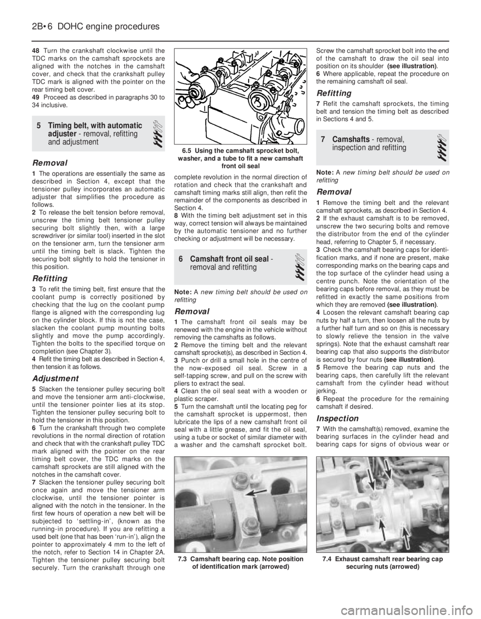
5Turn the camshaft until the locating peg for
the camshaft sprocket is uppermost, then
lubricate the lips of a new camshaft front oil
seal with a little grease, and fit the oil seal,
using a tube or socket of similar diameter with
a washer and the camshaft sprocket bolt.Screw the camshaft sprocket bolt into the end
of the camshaft to draw the oil seal into
position on its shoulder (see illustration).
6Where applicable, repeat the procedure on
the remaining camshaft oil seal.
Refitting
7Refit the camshaft sprockets, the timing
belt and tension the timing belt as described
in Sections 4 and 5.
7Camshafts- removal,
inspection and refitting
4
Note: A new timing belt should be used on
refitting
Removal
1Remove the timing belt and the relevant
camshaft sprockets, as described in Section 4.
2If the exhaust camshaft is to be removed,
unscrew the two securing bolts and remove
the distributor from the end of the cylinder
head, referring to Chapter 5, if necessary.
3Check the camshaft bearing caps for identi-
fication marks, and if none are present, make
corresponding marks on the bearing caps and
the top surface of the cylinder head using a
centre punch. Note the orientation of the
bearing caps before removal, as they must be
refitted in exactly the same positions from
which they are removed (see illustration).
4Loosen the relevant camshaft bearing cap
nuts by half a turn, then loosen all the nuts by
a further half turn and so on (this is necessary
to slowly relieve the tension in the valve
springs). Note that the exhaust camshaft rear
bearing cap that also supports the distributor
is secured by four nuts (see illustration).
5Remove the bearing cap nuts and the
bearing caps, then carefully lift the relevant
camshaft from the cylinder head without
jerking.
6Repeat the procedure for the remaining
camshaft if desired.
Inspection
7With the camshaft(s) removed, examine the
bearing surfaces in the cylinder head and
bearing caps for signs of obvious wear or
2B•6DOHC engine procedures
6.5 Using the camshaft sprocket bolt,
washer, and a tube to fit a new camshaft
front oil seal
7.4 Exhaust camshaft rear bearing cap
securing nuts (arrowed)7.3 Camshaft bearing cap. Note position
of identification mark (arrowed)
Page 215 of 525
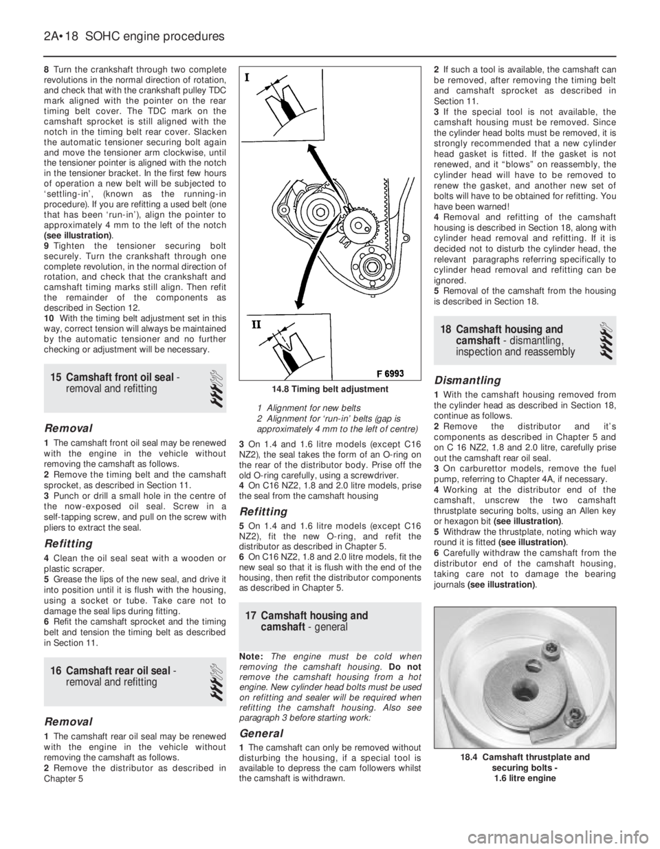
8Turn the crankshaft through two complete
revolutions in the normal direction of rotation,
and check that with the crankshaft pulley TDC
mark aligned with the pointer on the rear
timing belt cover. The TDC mark on the
camshaft sprocket is still aligned with the
notch in the timing belt rear cover. Slacken
the automatic tensioner securing bolt again
and move the tensioner arm clockwise, until
the tensioner pointer is aligned with the notch
in the tensioner bracket. In the first few hours
of operation a new belt will be subjected to
‘settling-in’, (known as the running-in
procedure). If you are refitting a used belt (one
that has been ‘run-in’), align the pointer to
approximately 4 mm to the left of the notch
(see illustration).
9Tighten the tensioner securing bolt
securely. Turn the crankshaft through one
complete revolution, in the normal direction of
rotation, and check that the crankshaft and
camshaft timing marks still align. Then refit
the remainder of the components as
described in Section 12.
10With the timing belt adjustment set in this
way, correct tension will always be maintained
by the automatic tensioner and no further
checking or adjustment will be necessary.
15Camshaft front oil seal -
removal and refitting
3
Removal
1The camshaft front oil seal may be renewed
with the engine in the vehicle without
removing the camshaft as follows.
2Remove the timing belt and the camshaft
sprocket, as described in Section 11.
3Punch or drill a small hole in the centre of
the now-exposed oil seal. Screw in a
self-tapping screw, and pull on the screw with
pliers to extract the seal.
Refitting
4Clean the oil seal seat with a wooden or
plastic scraper.
5Grease the lips of the new seal, and drive it
into position until it is flush with the housing,
using a socket or tube. Take care not to
damage the seal lips during fitting.
6Refit the camshaft sprocket and the timing
belt and tension the timing belt as described
in Section 11.
16Camshaft rear oil seal -
removal and refitting
3
Removal
1The camshaft rear oil seal may be renewed
with the engine in the vehicle without
removing the camshaft as follows.
2Remove the distributor as described in
Chapter 53On 1.4 and 1.6 litre models (except C16
NZ2), the seal takes the form of an O-ring on
the rear of the distributor body. Prise off the
old O-ring carefully, using a screwdriver.
4On C16 NZ2, 1.8 and 2.0 litre models, prise
the seal from the camshaft housing
Refitting
5 On 1.4 and 1.6 litre models (except C16
NZ2), fit the new O-ring, and refit the
distributor as described in Chapter 5.
6On C16 NZ2, 1.8 and 2.0 litre models, fit the
new seal so that it is flush with the end of the
housing, then refit the distributor components
as described in Chapter 5.
17Camshaft housing and
camshaft -general
Note: The engine must be cold when
removing the camshaft housing. Do not
remove the camshaft housing from a hot
engine. New cylinder head bolts must be used
on refitting and sealer will be required when
refitting the camshaft housing. Also see
paragraph 3 before starting work:
General
1The camshaft can only be removed without
disturbing the housing, if a special tool is
available to depress the cam followers whilst
the camshaft is withdrawn.2If such a tool is available, the camshaft can
be removed, after removing the timing belt
and camshaft sprocket as described in
Section 11.
3If the special tool is not available, the
camshaft housing must be removed. Since
the cylinder head bolts must be removed, it is
strongly recommended that a new cylinder
head gasket is fitted. If the gasket is not
renewed, and it “blows” on reassembly, the
cylinder head will have to be removed to
renew the gasket, and another new set of
bolts will have to be obtained for refitting. You
have been warned!
4Removal and refitting of the camshaft
housing is described in Section 18, along with
cylinder head removal and refitting. If it is
decided not to disturb the cylinder head, the
relevant paragraphs referring specifically to
cylinder head removal and refitting can be
ignored.
5Removal of the camshaft from the housing
is described in Section 18.
18Camshaft housing and
camshaft - dismantling,
inspection and reassembly
4
Dismantling
1With the camshaft housing removed from
the cylinder head as described in Section 18,
continue as follows.
2Remove the distributor and it’s
components as described in Chapter 5 and
on C 16 NZ2, 1.8 and 2.0 litre, carefully prise
out the camshaft rear oil seal.
3On carburettor models, remove the fuel
pump, referring to Chapter 4A, if necessary.
4Working at the distributor end of the
camshaft, unscrew the two camshaft
thrustplate securing bolts, using an Allen key
or hexagon bit (see illustration).
5Withdraw the thrustplate, noting which way
round it is fitted (see illustration).
6Carefully withdraw the camshaft from the
distributor end of the camshaft housing,
taking care not to damage the bearing
journals (see illustration).
2A•18SOHC engine procedures
14.8 Timing belt adjustment
1 Alignment for new belts
2 Alignment for ‘run-in’ belts (gap is
approximately 4 mm to the left of centre)
18.4 Camshaft thrustplate and
securing bolts -
1.6 litre engine
Page 247 of 525
REF•8MOTTest Checks
This is a guide to getting your vehicle through the MOT test.
Obviously it will not be possible to examine the vehicle to the same
standard as the professional MOT tester. However, working through
the following checks will enable you to identify any problem areas
before submitting the vehicle for the test.
Where a testable component is in borderline condition, the tester
has discretion in deciding whether to pass or fail it. The basis of such
discretion is whether the tester would be happy for a close relative or
friend to use the vehicle with the component in that condition. If the
vehicle presented is clean and evidently well cared for, the tester may
be more inclined to pass a borderline component than if the vehicle is
scruffy and apparently neglected.
It has only been possible to summarise the test requirements here,
based on the regulations in force at the time of printing. Test standards
are becoming increasingly stringent, although there are some
exemptions for older vehicles. For full details obtain a copy of the Haynes
publication Pass the MOT! (available from stockists of Haynes manuals).
An assistant will be needed to help carry out some of these checks.
The checks have been sub-divided into four categories, as follows:
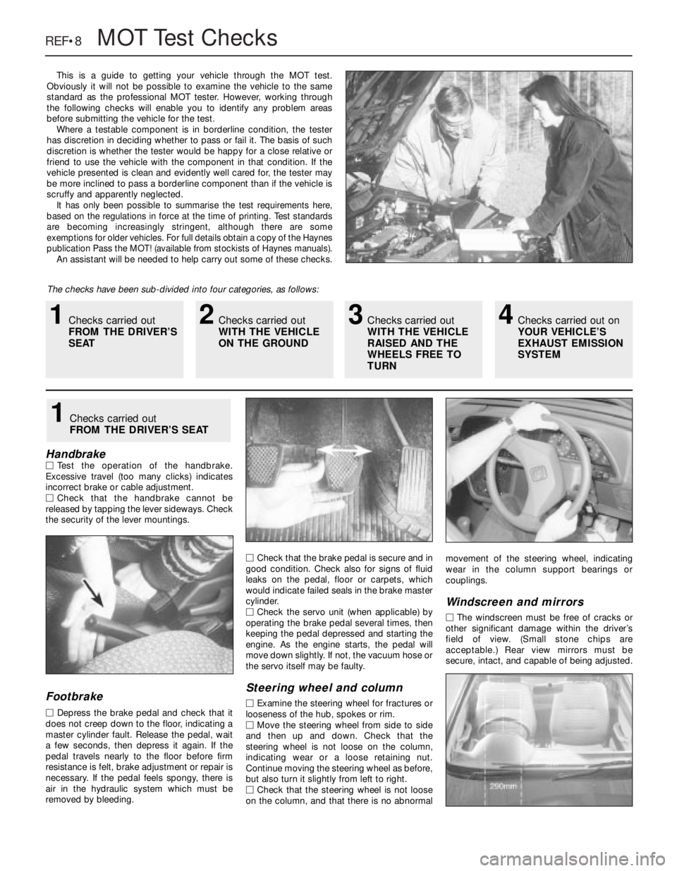
HandbrakeMTest the operation of the handbrake.
Excessive travel (too many clicks) indicates
incorrect brake or cable adjustment.
MCheck that the handbrake cannot be
released by tapping the lever sideways. Check
the security of the lever mountings.
Footbrake
MDepress the brake pedal and check that it
does not creep down to the floor, indicating a
master cylinder fault. Release the pedal, wait
a few seconds, then depress it again. If the
pedal travels nearly to the floor before firm
resistance is felt, brake adjustment or repair is
necessary. If the pedal feels spongy, there is
air in the hydraulic system which must be
removed by bleeding.MCheck that the brake pedal is secure and in
good condition. Check also for signs of fluid
leaks on the pedal, floor or carpets, which
would indicate failed seals in the brake master
cylinder.
MCheck the servo unit (when applicable) by
operating the brake pedal several times, then
keeping the pedal depressed and starting the
engine. As the engine starts, the pedal will
move down slightly. If not, the vacuum hose or
the servo itself may be faulty.
Steering wheel and column
MExamine the steering wheel for fractures or
looseness of the hub, spokes or rim.
MMove the steering wheel from side to side
and then up and down. Check that the
steering wheel is not loose on the column,
indicating wear or a loose retaining nut.
Continue moving the steering wheel as before,
but also turn it slightly from left to right.
MCheck that the steering wheel is not loose
on the column, and that there is no abnormalmovement of the steering wheel, indicating
wear in the column support bearings or
couplings.
Windscreen and mirrors
MThe windscreen must be free of cracks or
other significant damage within the driver’s
field of view. (Small stone chips are
acceptable.) Rear view mirrors must be
secure, intact, and capable of being adjusted.
1Checks carried out
FROM THE DRIVER’S SEAT
1Checks carried out
FROM THE DRIVER’S
SEAT2Checks carried out
WITH THE VEHICLE
ON THE GROUND3Checks carried out
WITH THE VEHICLE
RAISED AND THE
WHEELS FREE TO
TURN4Checks carried out on
YOUR VEHICLE’S
EXHAUST EMISSION
SYSTEM