Page 18 of 1378
\0032.5 L C EC S YSTE M
�
1988 J e ep C hero ke e
1988 Computerized Engine Controls
JEEP 4-CYLINDER 2.5L TBI COMPUTERIZED EMISSION CONTROL
Cherokee, Comanche
DESCRIPTION
The computerized engine control system, used on 2.5L models
with throttle body fuel injection, is built around an electronic
control unit (ECU). The ECU is a microprocessor-based computer.
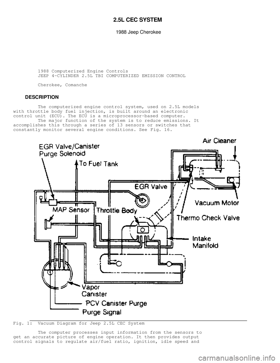
The major function of the system is to reduce emissions. It
accomplishes this through a series of 13 sensors or switches that
constantly monitor several engine conditions. See Fig. 16.
Fig. 1: Vacuum Diagram for Jeep 2.5L CEC System
The computer processes input information from the sensors to
get an accurate picture of engine operation. It then provides output
control signals to regulate air/fuel ratio, ignition, idle speed and
Page 53 of 1378
Fig. 28: Jeep 2.5L TBI System Wiring Diagram
FUEL PRESSURE REGULATOR
1) Remove air cleaner assembly. Connect a tachometer to
terminals 1 and 3 of small diagnostic connector D1. Remove screw plug
and install special Fuel Pressure Test Fitting (8983 501 572).
Page 87 of 1378
Fig. 10: ECU Connector Pin & Diagnostic Connector Pin Identification
WIRING DIAGRAM
Page 88 of 1378
Fig. 11: Comanche Engine Control System Wiring Diagram
Page 89 of 1378
Fig. 12: Cherokee Engine Control System Wiring Diagram
Page 115 of 1378
 To check system refrigerant level, a sight glass has been
incorporated into the receiver-to-evaporator hose at the receiver end.
A continuous stream of bubbles")
System Charge Test
1) To check system refrigerant level, a sight glass has been
incorporated into the receiver-to-evaporator hose at the receiver end.
A continuous stream of bubbles will appear in the sight glass of a
system that is not properly charged. However, both properly charged
systems and discharged systems will appear the same because of a lack
of bubbles.
2) To test for discharge condition, cycle the clutch off and
on with engine at 1500 RPM. When clutch is off, bubbles will appear if
there is refrigerant in the system. If no bubbles appear, system is
discharged. If discharged, leak test, repair and recharge system.
A/C SYSTEM OPERATION CHART & VACUUM DIAGRAM
A/C SYSTEM OPERATION TABLE������������������\
������������������\
������������������\
������������������\
������������������\
������������������\
������������������\
������������� �
MODE � � � � � � �
�
LEVER � � BLOWER � PANEL � FLOOR � DEFROST � WATER �
�
POSITION �AIR DISCHARGE� SPEEDS � DOOR � DOOR � DOOR � VALVE �
������������������\
��\f����������������\
�����������\f�������\
����������\f��������\
�������\f�����������\
����\f��������������\
�����\f�������������\
�����
�
Off(
1)( 2)� Closed � None � Open � ( 3) � Closed � Closed �
������������������\
��\f����������������\
�����������\f�������\
����������\f��������\
�������\f�����������\
����\f��������������\
�����\f�������������\
�����
�
Max A/C � Panel Regis-� 4 � � � � �
�
(
1)( 4) � ters With � � Open � Bleed � Closed � Open( 5)�
�
� Floor Bleed � � � � � �
������������������\
��\f����������������\
�����������\f�������\
����������\f��������\
�������\f�����������\
����\f��������������\
�����\f�������������\
�����
�
Norm A/C � Panel Regis-� 4(
6) � Open � Bleed � Closed � Open( 5)�
�
(
7)( 4) � ters With � � � � � �
�
� Floor Bleed � � � � � �
������������������\
��\f����������������\
�����������\f�������\
����������\f��������\
�������\f�����������\
����\f��������������\
�����\f�������������\
�����
�
Bi-Level � Panel � 4(
6) � Open � Open � Bleed � Open( 1)�
�
(
7)( 4) � Registers � � � � � �
�
� and Floor � � � � � �
�
� With Def. � � � � � �
�
� Bleed � � � � � �
������������������\
��\f����������������\
�����������\f�������\
����������\f��������\
�������\f�����������\
����\f��������������\
�����\f�������������\
�����
�
Vent � Panel � 4 � Open � Bleed � Closed � Closed �
�
(
7)( 2) � Registers � � � � � �
�
� With Floor � � � � � �
�
� Bleed � � � � � �
������������������\
��\f����������������\
�����������\f�������\
����������\f��������\
�������\f�����������\
����\f��������������\
�����\f�������������\
�����
�
Heat � Floor With � 4 � Closed� Open � Bleed � Open(
1)�
�
(
7)( 2) � Def. Bleed � � � � � �
������������������\
��\f����������������\
�����������\f�������\
����������\f��������\
�������\f�����������\
����\f��������������\
�����\f�������������\
�����
�
Def. � Defroster � 4 � Closed� Bleed � Open � Open(
1)�
�
(
7)( 2) � With Floor � � � � � �
�
� Bleed � � � � � �
������������������\
��
����������������\
�����������
�������\
����������
��������\
�������
�����������\
����
��������������\
�����
�������������\
�����
�
(
1) - Recirculating Door is in Recirc. position. �
�
(
2) - Indeterminate �
�
(
3) - A/C Compressor is OFF �
�
(
4) - A/C Compressor is ON �
�
(
5) - Water valve closes in full "COOL" temperature lever position. �
�
(
6) - Speeds are reduced by approximately 2.0 Volts. �
�
(
7) - Recirculating Door is in Outside position. �
�
������������������\
������������������\
������������������\
������������������\
������������������\
������������������\
������������������\
����������\b
Page 116 of 1378
Fig. 7: A/C Control System Vacuum Diagram
Page 267 of 1378
Fig. 117: Test 10A - Location of Transmission Connectors
Fig. 118: Test 10A - View of 7-Way Connector (Cherokee)
NOTE: See Fig. 115 for wiring diagram.
 Remove air cleaner assembly. Connect a tachometer to
terminals 1 and 3 of small diagnostic connector D1. Remo")


NOTE: See Fig. 115 for wiring diagram.")