Page 823 of 1378
Fig. 26: Wrangler Throttle Body Fuel Injection System Wiring Diagram
Page 841 of 1378

Remove retaining clip and cable self-adjusting clip from blend-air
door lever at bottom of blower housing. Remove cable by squeezing tabs
with needle nose pliers. Do not break housing.
INSTALLATION
To install, connect cable self-adjusting clip to blend-air
door lever, then snap cable into position. Install retaining clip onto
blend-air door lever. Route cable to A/C-heater control panel and
connect. Install control panel.
REMOVAL & INSTALLATION (WRANGLER)
1) Disconnect cables from vent doors. Disconnect cables from
heater control panel levers. Remove cables by squeezing tabs with
needle nose pliers.
2) Connect and adjust cables as described in ADJUSTMENTS
section of this article
HEATER CORE R & I
REMOVAL & INSTALLATION (CHEROKEE & COMANCHE)
1) Disconnect battery ground. Drain cooling system.
Disconnect heater hoses at heater core inlet and outlet tubes.
Disconnect blower motor wires and vent tube. Remove console (if
equipped). Remove lower instrument panel.
2) Disconnect electrical connectors from blower motor
resistors. Disconnect vacuum hose at vacuum motor. Cut plastic
retaining strap holding blower housing to heater core housing.
3) Disconnect and remove heater control cable. Detach clip at
rear of blower housing flange and remove retaining screws. Remove
housing mounting nuts from studs on engine compartment side of dash
panel. Remove right kick panel.
4) Remove instrument panel support bolt. Gently pull on right
side of dash, then rotate housing downward and toward rear of vehicle
to disengage housing studs from dash panel. Remove blower housing.
Detach retaining screws and remove heater core by pulling it straight
out of housing.
5) To install, reverse removal procedure. Ensure seal is
cemented in place to prevent movement when blower assembly is
installed. Connect heater hoses and fill cooling system.
REMOVAL & INSTALLATION (WRANGLER)
1) Disconnect battery ground. Drain about 2 quarts of coolant
from radiator. Disconnect heater hoses at heater core inlet and outlet
tubes. Disconnect vent door cables. Disconnect blower motor wires.
Disconnect defroster duct.
2) Remove nuts attaching heater housing studs to engine
compartment side of dash panel. Remove heater housing assembly by
tilting it downward, to disengage it from defroster duct.
3) Pull heater housing rearward and out from under instrument
panel. Remove heater housing cover from heater housing assembly.
Remove heater core from housing.
HEATER SYSTEM OPREATION CHART & VACUUM DIAGRAM
HEATER SYSTEM OPERATION TABLE������������������\
������������������\
������������������\
������������������\
������������������\
������������������\
������������������\
������������� �
MODE � � � � � � �
Page 842 of 1378

� LEVER � � BLOWER � PANEL � FLOOR � DEFROST � WATER �
�
POSITION �AIR DISCHARGE� SPEEDS � DOOR � DOOR � DOOR � VALVE �
�
������������������\
��\b����������������\
�����������\b�������\
����������\b��������\
�������\b�����������\
����\b��������������\
�����\b�������������\
����
�
Off � Closed � None � Closed� Closed� Closed � Closed �
�
������������������\
��\b����������������\
�����������\b�������\
����������\b��������\
�������\b�����������\
����\b��������������\
�����\b�������������\
����
�
Vent � Panel � 4 � Open � Closed� Closed � Closed �
�
� Registers � � � � � �
�
������������������\
��\b����������������\
�����������\b�������\
����������\b��������\
�������\b�����������\
����\b��������������\
�����\b�������������\
����
�
Bi-Level � Panel � 4 � Open � Open � Bleed � Open
(1)�
�
� Registers � � � � � �
�
� and Floor � � � � � �
�
� With Def. � � � � � �
�
� Bleed � � � � � �
�
������������������\
��\b����������������\
�����������\b�������\
����������\b��������\
�������\b�����������\
����\b��������������\
�����\b�������������\
����
�
Heat � Floor With � 4 � Closed� Open � Bleed � Open
(1)�
�
� Def. Bleed � � � � � �
�
������������������\
��\b����������������\
�����������\b�������\
����������\b��������\
�������\b�����������\
����\b��������������\
�����\b�������������\
����
�
Def. � Defroster � 4 � Closed� Closed� Open � Open
(1)�
�
� � � � � � �
�
������������������\
��
����������������\
�����������
�������\
����������
��������\
�������
�����������\
����
��������������\
�����
�������������\
����
�
(1)
- Water valve closes in full "COOL" temperature lever position. �
�
������������������\
������������������\
������������������\
������������������\
������������������\
������������������\
������������������\
����������\f
Fig. 3: Heater Control System Vacuum Diagram
WIRING DIAGRAMS
Page 843 of 1378
Fig. 4: Heater Wiring Diagram (Comanche Diesel)
Page 844 of 1378
Fig. 5: Heater Wiring Diagram (Comanche Gas)
Fig. 6: Heater Wiring Diagram (Wrangler)
Page 880 of 1378
\003
IG NIT IO N S YSTE M - 4 .0 L W /H EI/E ST/E SC ( D ELC O -R EM Y)
�
1 988 J e ep C hero ke e
Distributors & Ignition Systems
HEI, HEI/EST & HEI/EST/ESC IGNITION SYSTEM
Jeep 4.0L
DESCRIPTION
HIGH ENERGY IGNITION (HEI)
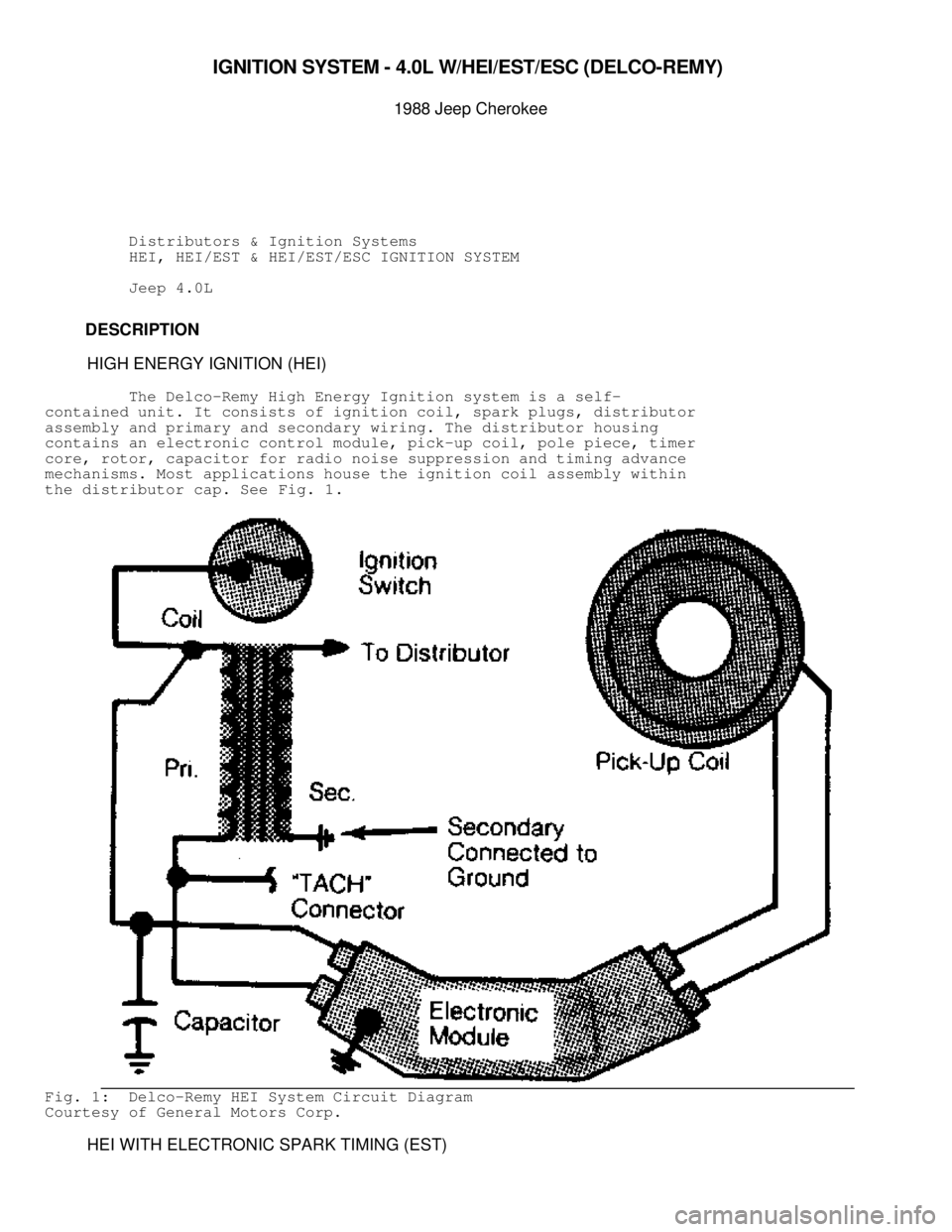
The Delco-Remy High Energy Ignition system is a self-
contained unit. It consists of ignition coil, spark plugs, distributor
assembly and primary and secondary wiring. The distributor housing
contains an electronic control module, pick-up coil, pole piece, timer
core, rotor, capacitor for radio noise suppression and timing advance
mechanisms. Most applications house the ignition coil assembly within
the distributor cap. See Fig. 1.
Fig. 1: Delco-Remy HEI System Circuit Diagram
Courtesy of General Motors Corp.
HEI WITH ELECTRONIC SPARK TIMING (EST)
Page 884 of 1378

Fig. 4: Circuit Diagram of HEI/EST Ignition System
Courtesy of General Motors Corp.
ADJUSTMENTS
The only adjustments that can be made to HEI/EST igntion
system are basic ignition timing and spark plug gap.
DIAGNOSIS
If reference or EST signals are interrupted due to an open
circuit or a faulty ECM, HEI/EST module will provide a timing signal
based on engine RPM. Engine may continue to run, although less
efficiently. If by-pass signal is lost, by-pass switch will direct RPM
information directly to coil rather than to ECM.
Normally, 5-15 seconds after starting a warm engine, by-pass
signal from ECM will operate a by-pass switch in HEI/EST module. The
HEI/EST module's RPM-controlled timing signal will switch over and RPM
signal will flow directly to the ECM for processing.
Loss of EST signal from ECM when 5-volt by-pass signal is
present will cause engine to stop because HEI/EST module is no longer
sending signals directly to ignition coil. Any loss of EST signal will
stop all flow to coil. If vehicle is restarted, engine will run for a
few seconds and stop when by-pass signal comes back on.
COMPONENT TESTING (HEI)
ELECTRONIC MODULE
NOTE: Testing applies to HEI systems with mechanical weights and
vacuum advance only.
1) An approved electronic module tester must be used to test
the module. Use Module Tester (J-24642-E). Follow manufacturer's
instructions.
2) When installing a new HEI control module, use silicone
Page 1205 of 1378

TORQUE SPECIFICATIONS
TORQUE SPECIFICATIONS TABLE������������������\
������������������\
������������������\
������������������\
������������������\
������������������\
�����������
Application Ft. Lbs. (N.m)
Companion Flange Nut
Chrysler Corp. ....................... 130-200 (176-271)
General Motors ................................ 80 (108)
Jeep ......................................... 110 (149)
Detent Plug
General Motors ................................. 11 (15)
Chrysler Corp. & Jeep .......................... 15 (20)
Drain & Fill Plug .......................... 30-40 (41-54)
Extension Housing Bolt ..................... 20-25 (27-34)
Front Bearing Retainer Bolt
Chrysler Corp. & Jeep .......................... 16 (22)
General Motors ................................. 14 (19)
Front Case-to-Rear Case Bolt
Chrysler Corp.
Flange Head Bolt ........................ 35-45 (47-61)
All Other Bolts ........................ 20-25 (27-34)
General Motors ................................. 23 (31)
Jeep ..................................... 20-25 (27-34)
Range Lever Nut ............................ 15-20 (20-27)
Rear Bearing Retainer Bolt ................. 20-25 (27-34)
Rear Crossmember ................................. 30 (41)
Shift Lever Lock Bolt ............................ 10 (14)
Speed Sensor Bolt ................................ 23 (31)
Transfer Case-to-Transmission Nut ................ 26 (35)
Vacuum Switch
Chrysler Corp. ........................... 15-25 (20-34)
General Motors ................................. 17 (23)
Jeep ..................................... 20-25 (27-34)
INCH Lbs.
Control Cable Lock Nut ............................ 18 (2)
������������������\
������������������\
������������������\
������������������\
������������������\
������������������\
�����������
VACUUM DIAGRAMS
For vacuum diagrams, refer to appropriate VACUUM DIAGRAMS
article in the ENGINE PERFORMANCE section.

")

Fig. 6: Heater Wiring Diagram (Wrangler)")