1988 FIAT TEMPRA check oil
[x] Cancel search: check oilPage 47 of 171

28C. With very latest
'distributorless' system,
disconnect the multi-plug
from the base of the 'black
box'.
28D. With the two earlier
systems, disconnect the
multi-plug leading to the
distributor/control unit
from the ignition coil
behind the battery.
FACT FILE: CRANKING AN ENGINE
WITH ELECTRONIC IGNITION
Severe damage can be
caused to the ignition
system if the engine is
cranked with plugs/leads
removed
-
and a severe
electric shock can be
experienced.
PART E: FUEL AND EXHAUST
SAFETY FIRST!
Always
wear impervious gloves so that fuel cannot
come
in contact with your
skin.
It can induce cancer.
Q Job 29. Check fuel pipes for leaks.
Check the fuel lines from the fuel tank and into the engine
compartment, looking for signs of chafing, splits and perishing
of the
rubber and plastic parts. Ensure any worm-drive hose
clips used
on the connections are firm and secure.
Q Job 30. Change petrol air filter.
IMPORTANT NOTE: If the HC reading when measured at
the end of the exhaust pipe is outside of the recom-
mended limit while that measured upstream of the
catalytic converter is OK, the cat. is almost certainly
faulty. Have it double-checked by your dealer before
replacing it
-
an expensive component!
30C. Pull on the
tabs
-
and watch
that the springs
don't fall on the
floor as you release
the catches!
30D. Lower the
filter cover and lift
out the filter
element.
31B. If you want to
take the cover right
off, you will have to
unscrew the air
hose clamp
(arrowed). Remove
and replace the
filter element (A).
• Job 31.
Change diesel
air filter.
31A. Take out the
four screws
(arrowed) and lift
off the cover (B). 30B. ...and release
the two
fasteners
(a) and the
two
spring clips
(b).
30A. Unscrew the
two
screws
(arrowed)...
51
Page 48 of 171
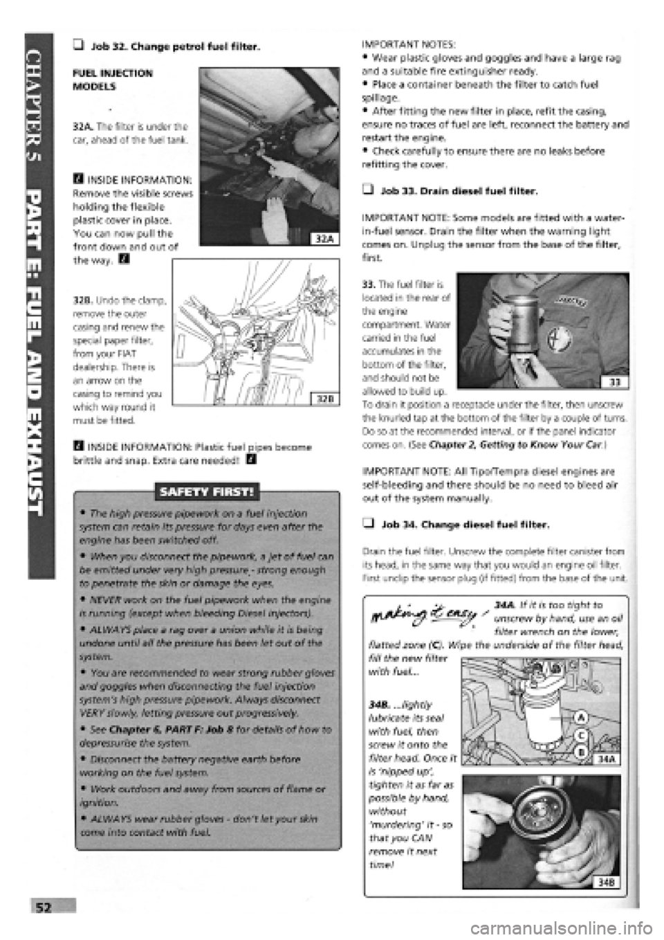
• Job 32. Change petrol fuel filter. IMPORTANT NOTES:
• Wear plastic gloves and goggles and have a large rag
and a suitable fire extinguisher ready.
• Place a container beneath the filter to catch fuel
spillage.
• After fitting the new filter in place, refit the casing,
ensure no traces of fuel are left, reconnect the battery and
restart the engine.
• Check carefully to ensure there are no leaks before
refitting the cover.
• Job 33. Drain diesel fuel filter.
IMPORTANT NOTE: Some models are fitted with a water-
in-fuel sensor. Drain the filter when the warning light
comes on. Unplug the sensor from the base of the filter,
first.
FUEL INJECTION
MODELS
32A. The filter is under the
car, ahead of the fuel tank.
E3 INSIDE INFORMATION:
Remove the visible screws
holding the flexible
plastic cover in place.
You can now pull the
front down and out of
the way. E3
32B. Undo the clamp,
remove the outer
casing and renew the
special paper filter,
from your FIAT
dealership. There is
an arrow on the
casing to remind you
which way round it
must be fitted.
33. The fuel filter is
located in the rear of
the engine
compartment. Water
carried in the fuel
accumulates in the
bottom of the filter,
and should not be
allowed to build up.
To drain it position a receptacle under the filter, then unscrew
the knurled tap at the bottom of the filter by a couple of turns.
Do so at the recommended interval, or if the panel indicator
comes on. (See Chapter
2,
Getting to Know Your
Car.)
H INSIDE INFORMATION: Plastic fuel pipes become
brittle and snap. Extra care needed! E3
SAFETY FIRST!
• The high pressure pipework on a fuel injection
system can retain its pressure for days even after the
engine has been switched off.
• When you disconnect the pipework, a jet of fuel can
be emitted under very high pressure
-
strong enough
to penetrate the skin or damage the eyes.
• NEVER work on the fuel pipework when the engine
is running (except when bleeding Diesel injectors).
• ALWAYS place a rag over a union while it is being
undone until all the pressure has been let out of the
system.
• You are recommended to wear strong rubber gloves
and goggles when disconnecting the fuel injection
system's high pressure pipework. Always disconnect
VERY slowly, letting pressure out progressively.
• See Chapter 6, PART F: Job 8 for details of how to
depressurise the system.
• Disconnect the battery negative earth before
working on the fuel system.
• Work outdoors and away from sources of flame or
ignition.
• ALWAYS wear rubber gloves
-
don't let your
skin
come into contact with fuel.
IMPORTANT NOTE: All Tipo/Tempra diesel engines are
self-bleeding and there should be no need to bleed air
out of the system manually.
• Job 34. Change diesel fuel filter.
Drain the fuel filter. Unscrew the complete filter canister from
its head, in the same way that you would an engine oil filter.
First undip the sensor plug (if fitted) from the base of the unit.
^ 34A. If it is too tight to
^^ - unscrew by hand, use an oil
filter wrench on the lower,
flatted zone (C). Wipe the underside of the filter head,
fill the new filter
with fuel...
34B. ...lightly
lubricate its seal
with fuel, then
screw it onto the
filter head. Once it
is 'nipped up',
tighten it as far as
possible by hand,
without
'murdering' it
-
so
that you CAN
remove it next
time!
Page 53 of 171
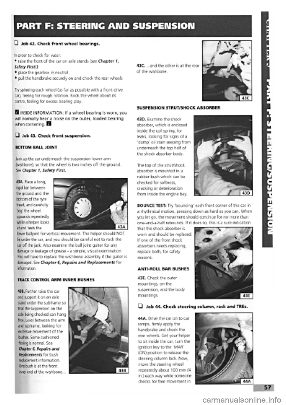
PART F: STEERING AMD SUSPENSION
G Job 42. Check front wheel bearings.
In
order to check for wear:
• raise the front of the car on axle stands (see Chapter 1,
Safety First!)
• place the gearbox in neutral
• pull the handbrake securely on and chock the rear wheels
Try
spinning each wheel (as far as possible with a front-drive
car), feeling for rough rotation. Rock the wheel about its
centre, feeling for excess bearing play.
D INSIDE INFORMATION: If a wheel bearing is worn, you
will normally hear a noise on the outer, loaded bearing
when cornering. D
G Job 43. Check front suspension.
BOTTOM BALL JOINT
Jack
up
the car underneath the suspension lower arm
(wishbone), so that the wheel is two inches off the ground.
See Chapter
1,
Safety First.
SUSPENSION STRUT/SHOCK ABSORBER
43D. Examine the shock
absorber, which is enclosed
inside the coil spring, for
leaks, looking for signs of a
'damp' oil stain seeping from
underneath the top half of
the shock absorber body.
The top of the strut/shock
absorber is mounted in a
rubber bush which can be
checked for softness,
cracking or deterioration
from inside the engine bay.
43A. Place a long,
rigid bar between
the
ground and the
bottom of the tyre
tread, and carefully
'jog' the wheel
upwards repeatedly
while a helper looks
at and
feels the
lower balljoint for vertical movement. The helper should NOT
lie
under the car, and you should be careful not to rock the
car
off
the jack.
Also examine the ball joint gaiter for any
damage
or leakage of grease
-
a simple, visual examination.
You will
have to replace the wishbone assembly if the gaiter is
damaged. See Chapter
6,
Repairs and Replacements for
information.
TRACK CONTROL ARM INNER BUSHES
43B. Further raise the car
and
support it on an axle
stand
under the subframe so
that the
suspension on the
side being
checked can hang
free. Lever between the arm
and
subframe, looking for
excessive movement of the
bushes. Some cushioned
flexing
is
normal. See
Chapter
6, Repairs and
Replacements for bush
replacement information.
One bush is
at the front
inner end
of the wishbone...
ANTI-ROLL BAR BUSHES
43E. Check the outer
mountings, on the
suspension, and the body
mountings.
• Job 44. Check steering column, rack and TREs.
44A. Drive the car on to car
ramps, firmly apply the
handbrake and chock the
rear wheels. Get your helper
to sit inside the car, turn the
ignition key to the 'MAR'
(ON) position to release the
steering column lock. Now,
move the steering wheel
repeatedly about 100 mm (4
in.) each way while someone
checks for free movement in
BOUNCE TEST: Try 'bouncing' each front corner of the car in
a rhythmical motion, pressing down as hard as you can. When
you let go, the movement should continue for no more than
one-and-a-half rebounds. If it does so, this is a sure indication
that the shock absorber is
worn and should be replaced.
If one of the front shock
absorbers needs replacing,
replace both, for safety
reasons.
Page 54 of 171
each track rod end (TRE). Also, look out for a split gaiter.
Replace the TRE if the gaiter is split, or it will rapidly fail.
E3 INSIDE INFORMATION: Try placing your hand over the
TRE as the steering is moved. If there are any signs of
wear, replace the TRE. Q
STEERING COLUMN
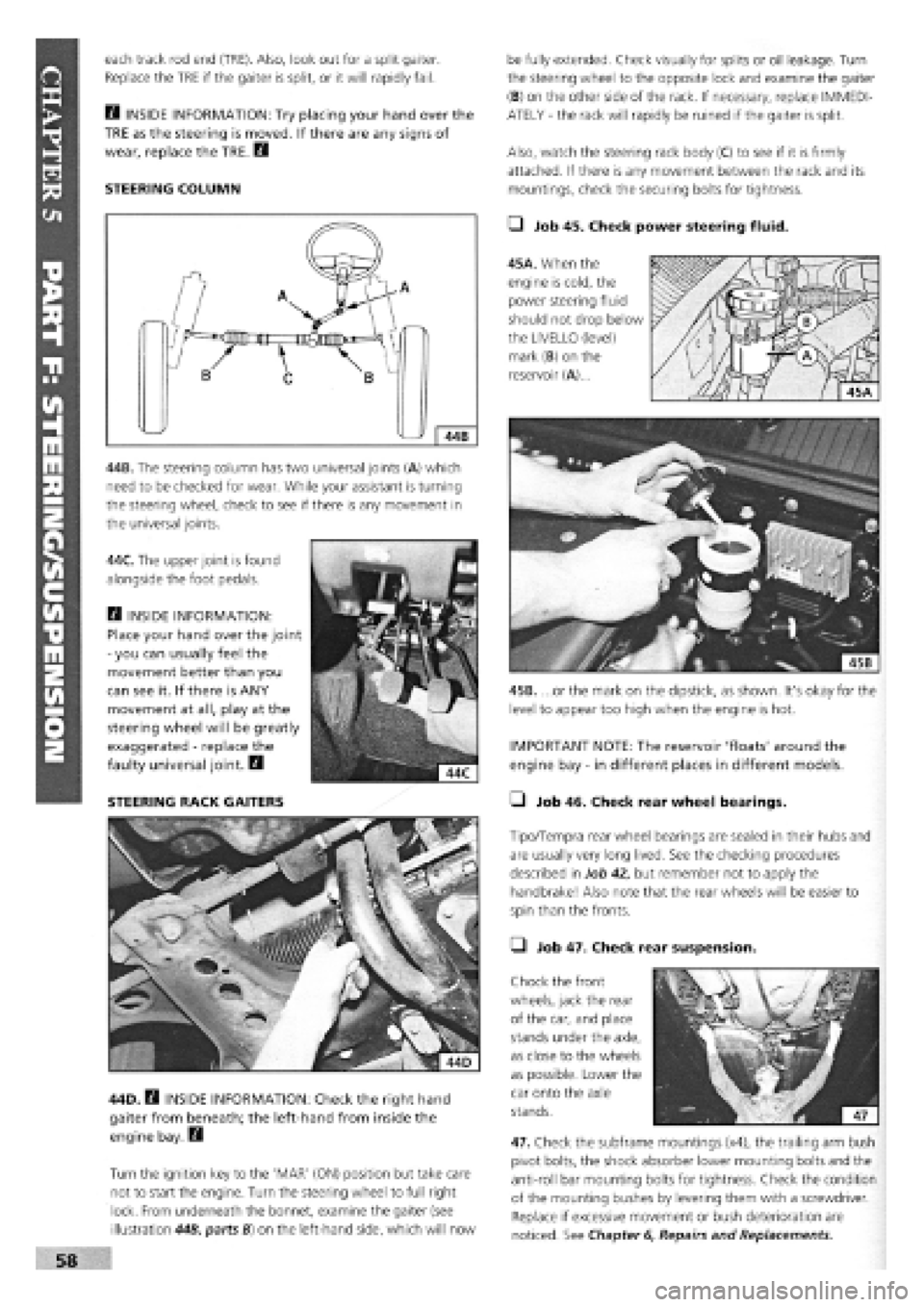
44B. The steering column has two universal joints (A) which
need to be checked for wear. While your assistant is turning
the steering wheel, check to see if there is any movement in
the universal joints.
44C. The upper joint is found
alongside the foot pedals.
Q INSIDE INFORMATION:
Place your hand over the joint
-
you can usually feel the
movement better than you
can see it. If there is ANY
movement at all, play at the
steering wheel will be greatly
exaggerated
-
replace the
faulty universal joint. B
STEERING RACK GAITERS
44D. B INSIDE INFORMATION: Check the right hand
gaiter from beneath; the left-hand from inside the
engine bay. Q
Turn the ignition key to the 'MAR' (ON) position but take care
not to start the engine. Turn the steering wheel to full right
lock. From underneath the bonnet, examine the gaiter (see
illustration 44B, parts B) on the left-hand side, which will now
be fully extended. Check visually for splits or oil leakage. Turn
the steering wheel to the opposite lock and examine the gaiter
(B) on the other side of the rack. If necessary, replace IMMEDI-
ATELY
-
the rack will rapidly be ruined if the gaiter is split.
Also, watch the steering rack body (C) to see if it is firmly
attached. If there is any movement between the rack and its
mountings, check the securing bolts for tightness.
• Job 45. Check power steering fluid.
45A. When the
engine is cold, the
power steering fluid
should not drop below
the LIVELLO (level)
mark (B) on the
reservoir (A)...
45B. ...or the mark on the dipstick, as shown. It's okay for the
level to appear too high when the engine is hot.
IMPORTANT NOTE: The reservoir 'floats' around the
engine bay
-
in different places in different models.
• Job 46. Check rear wheel bearings.
Tipo/Tempra rear wheel bearings are sealed in their hubs and
are usually very long lived. See the checking procedures
described in Job 42, but remember not to apply the
handbrake! Also note that the rear wheels will be easier to
spin than the fronts.
• Job 47. Check rear suspension.
Chock the front
wheels, jack the rear
of the car, and place
stands under the axle,
as close to the wheels
as possible. Lower the
car onto the axle
stands.
47. Check the subframe mountings (x4), the trailing arm bush
pivot bolts, the shock absorber lower mounting bolts and the
anti-roll bar mounting bolts for tightness. Check the condition
of the mounting bushes by levering them with a screwdriver.
Replace if excessive movement or bush deterioration are
noticed. See Chapter
6,
Repairs and Replacements.
Page 57 of 171
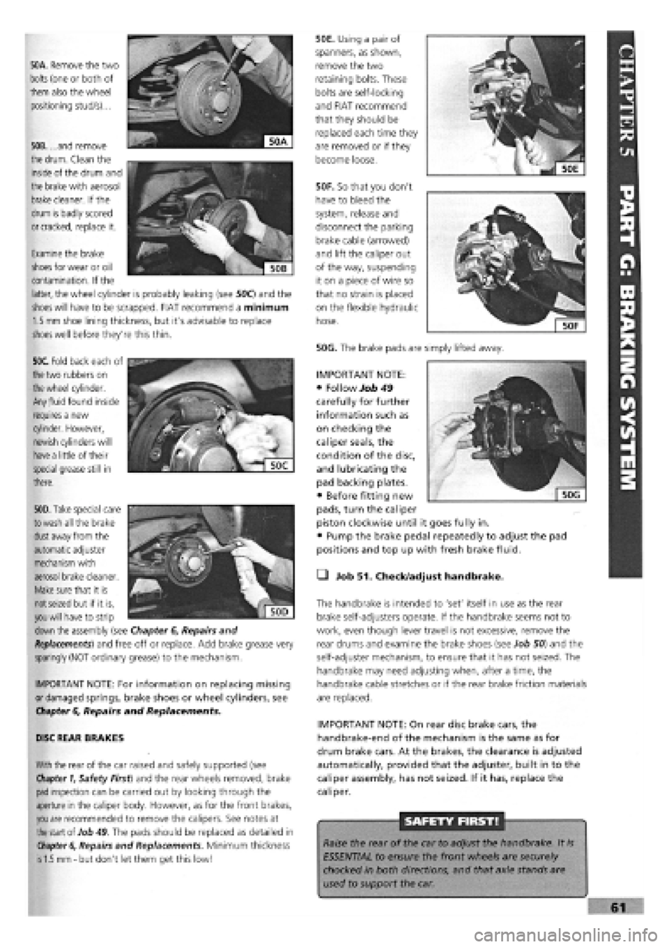
50A. Remove the two
bolts
(one or both of
them also the wheel
positioning stud/s)...
50B. ...and remove
the
drum.
Clean the
inside of the drum and
the brake with aerosol
brake
cleaner. If the
drum is badly scored
or cracked,
replace it.
50F. So that you don't
have to bleed the
system, release and
disconnect the parking
brake cable (arrowed)
and lift the caliper out
of the way, suspending
it on a piece of wire so
that no strain is placed
on the flexible hydraulic
hose.
50G. The brake pads are simply lifted away.
50E. Using a pair of
spanners, as shown,
remove the two
retaining bolts. These
bolts are self-locking
and FIAT recommend
that they should be
replaced each time they
are removed or if they
become loose.
Examine the brake
shoes
for wear or oil
contamination. If the
latter, the wheel cylinder is probably leaking (see 50C) and the
shoes will
have to be scrapped. FIAT recommend a minimum
1.5 mm
shoe lining thickness, but it's advisable to replace
shoes
well before they're this thin.
50C. Fold back each of
the
two rubbers on
the wheel
cylinder.
Any
fluid
found inside
requires a new
cylinder. However,
newish cylinders will
have a
little of their
special grease still in
there.
. """
€
Sjjj
KV,1
| 50D|
50D. Take
special care
to wash
all the brake
dust
away from the
automatic adjuster
mechanism with
aerosol brake cleaner.
Make
sure that it is
not seized
but if it is,
you will
have to strip
down
the assembly (see Chapter
6,
Repairs and
Replacements)
and free off or replace. Add brake grease very
sparingly (NOT ordinary grease) to the mechanism.
IMPORTANT NOTE: For information on replacing missing
or damaged springs, brake shoes or wheel cylinders, see
Chapter
6,
Repairs and Replacements.
DISC REAR BRAKES
With
the rear of the car raised and safely supported (see
Chapter 1,
Safety First) and the rear wheels removed, brake
pad
inspection can be carried out by looking through the
aperture in the caliper body. However, as for the front brakes,
you are
recommended to remove the calipers. See notes at
the
start of Job
49.
The pads should be replaced as detailed in
Chapter 6,
Repairs and Replacements. Minimum thickness
is 1.5 mm -
but don't let them get this low!
• Job 51. Check/adjust handbrake.
The handbrake is intended to 'set' itself in use as the rear
brake self-adjusters operate. If the handbrake seems not to
work, even though lever travel is not excessive, remove the
rear drums and examine the brake shoes (see Job 50) and the
self-adjuster mechanism, to ensure that it has not seized. The
handbrake may need adjusting when, after a time, the
handbrake cable stretches or if the rear brake friction materials
are replaced.
IMPORTANT NOTE: On rear disc brake cars, the
handbrake-end of the mechanism is the same as for
drum brake cars. At the brakes, the clearance is adjusted
automatically, provided that the adjuster, built in to the
caliper assembly, has not seized. If it has, replace the
caliper.
SAFETY FIRST!
Raise the rear of the car to adjust the handbrake. It
is
ESSENTIAL to ensure the front wheels are securely
chocked in both directions, and that axle stands are
used to support the car.
IMPORTANT NOTE:
• Follow Job 49
carefully for further
information such as
on checking the
caliper seals, the
condition of the disc,
and lubricating the
pad backing plates.
• Before fitting new
pads, turn the caliper
piston clockwise until it goes fully in.
• Pump the brake pedal repeatedly to adjust the pad
positions and top up with fresh brake fluid.
Page 58 of 171
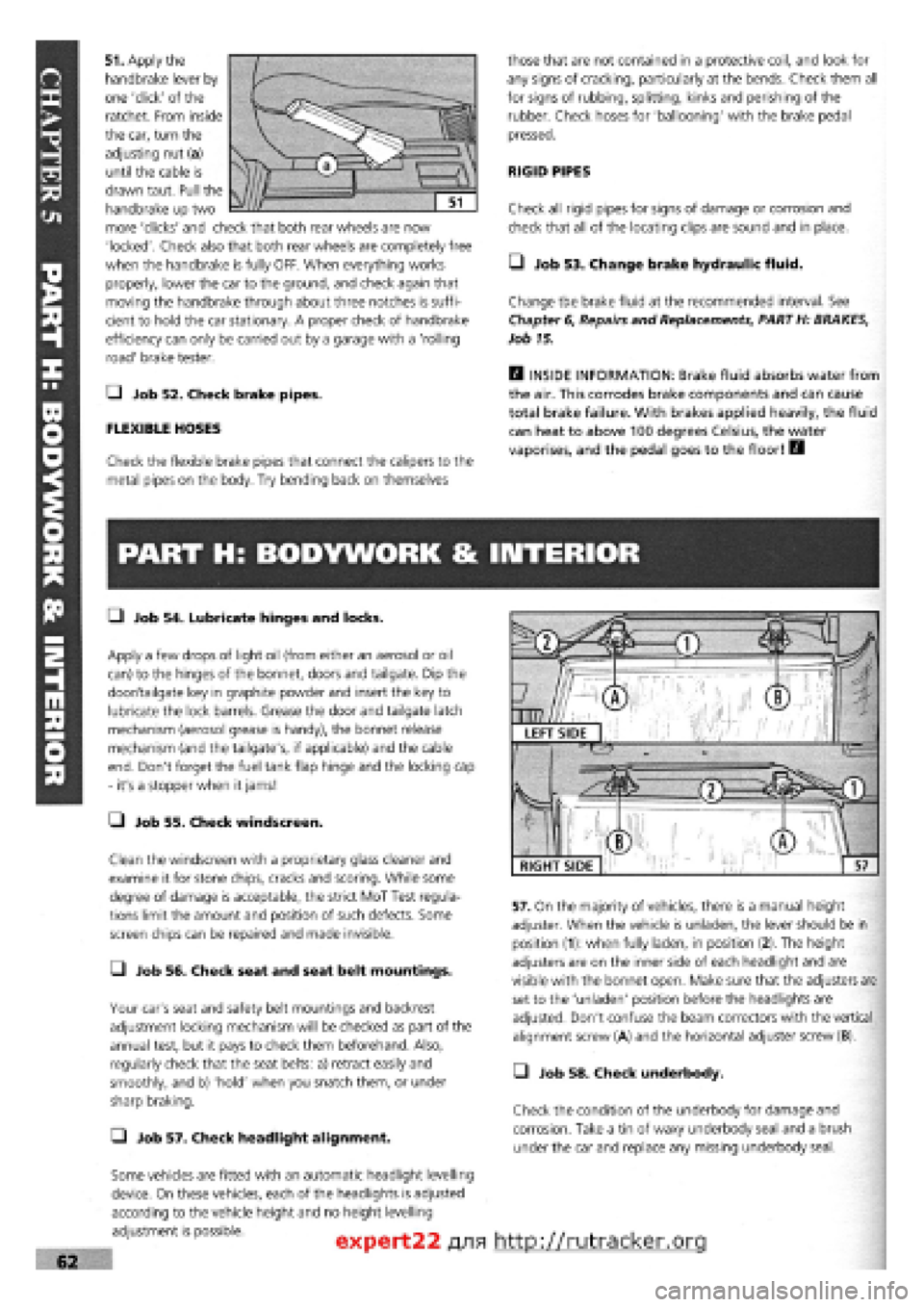
51. Apply the
handbrake lever by
one 'click' of the
ratchet. From inside
the car, turn the
adjusting nut (a)
until the cable is
drawn taut. Pull the
handbrake up two
more 'clicks' and check that both rear wheels are now
'locked'. Check also that both rear wheels are completely free
when the handbrake is fully OFF. When everything works
properly, lower the car to the ground, and check again that
moving the handbrake through about three notches is suffi-
cient to hold the car stationary. A proper check of handbrake
efficiency can only be carried out by a garage with a 'rolling
road' brake tester.
Q Job 52. Check brake pipes.
FLEXIBLE HOSES
Check the flexible brake pipes that connect the calipers to the
metal pipes on the body. Try bending back on themselves
those that are not contained in a protective coil, and look for
any signs of cracking, particularly at the bends. Check them all
for signs of rubbing, splitting, kinks and perishing of the
rubber. Check hoses for 'ballooning' with the brake pedal
pressed.
RIGID PIPES
Check all rigid pipes for signs of damage or corrosion and
check that all of the locating clips are sound and in place.
• Job 53. Change brake hydraulic fluid.
Change the brake fluid at the recommended interval. See
Chapter
6,
Repairs and Replacements, PART H: BRAKES,
Job 15.
H INSIDE INFORMATION: Brake fluid absorbs water from
the air. This corrodes brake components and can cause
total brake failure. With brakes applied heavily, the fluid
can heat to above 100 degrees Celsius, the water
vaporises, and the pedal goes to the floor! B
PART H: BODYWORK & INTERIOR
• Job 54. Lubricate hinges and locks.
Apply a few drops of light oil (from either an aerosol or oil
can) to the hinges of the bonnet, doors and tailgate. Dip the
door/tailgate key in graphite powder and insert the key to
lubricate the lock barrels. Grease the door and tailgate latch
mechanism (aerosol grease is handy), the bonnet release
mechanism (and the tailgate's, if applicable) and the cable
end. Don't forget the fuel tank flap hinge and the locking cap
- it's a stopper when it jams!
• Job 55. Check windscreen.
Clean the windscreen with a proprietary glass cleaner and
examine it for stone chips, cracks and scoring. While some
degree of damage is acceptable, the strict MoT Test regula-
tions limit the amount and position of such defects. Some
screen chips can be repaired and made invisible.
• Job 56. Check seat and seat belt mountings.
Your car's seat and safety belt mountings and backrest
adjustment locking mechanism will be checked as part of the
annual test, but it pays to check them beforehand. Also,
regularly check that the seat belts: a) retract easily and
smoothly, and b) 'hold' when you snatch them, or under
sharp braking.
Q Job 57. Check headlight alignment.
Some vehicles are fitted with an automatic headlight levelling
device. On these vehicles, each of the headlights is adjusted
according to the vehicle height and no height levelling
adjustment is possible.
57. On the majority of vehicles, there is a manual height
adjuster. When the vehicle is unladen, the lever should be in
position (1): when fully laden, in position (2). The height
adjusters are on the inner side of each headlight and are
visible with the bonnet open. Make sure that the adjusters are
set to the 'unladen' position before the headlights are
adjusted. Don't confuse the beam correctors with the vertical
alignment screw (A) and the horizontal adjuster screw (B).
• Job 58. Check underbody.
Check the condition of the underbody for damage and
corrosion. Take a tin of waxy underbody seal and a brush
under the car and replace any missing underbody seal.
expert22 fl/ia http://rutracker.org
RIGHT SIDE
Page 62 of 171
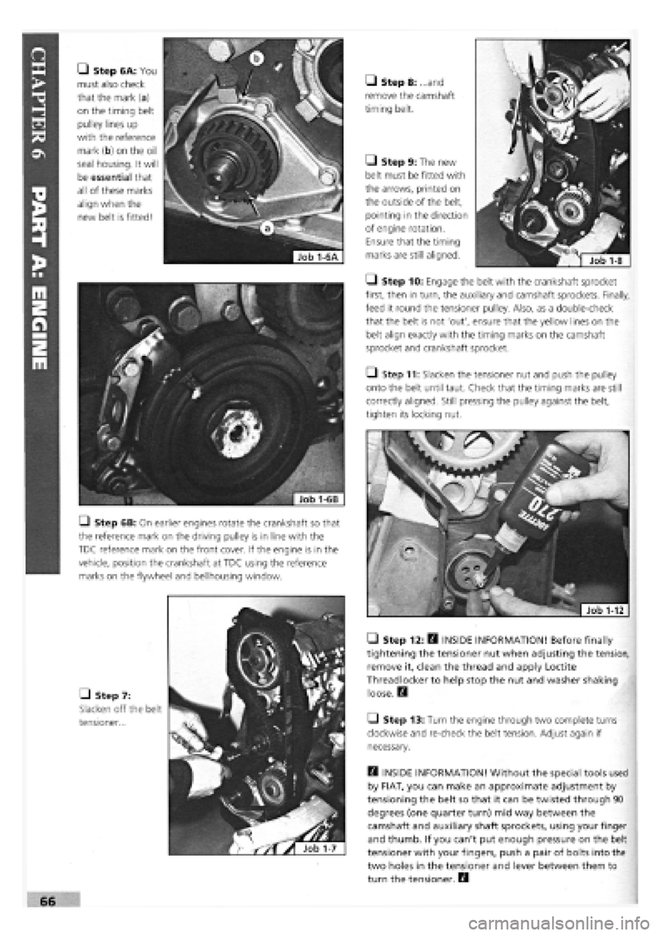
• Step 6A: You
must also check
that the mark (a)
on the timing belt
pulley lines up
with the reference
mark (b) on the oil
seal housing. It will
be essential that
all of these marks
align when the
new belt is fitted!
Q Step 6B: On earlier engines rotate the crankshaft so that
the reference mark on the driving pulley is in line with the
TDC reference mark on the front cover. If the engine is in the
vehicle, position the crankshaft at TDC using the reference
marks on the flywheel and bellhousing window.
• Step 7:
Slacken off the belt
tensioner...
• Step 8: ...and
remove the camshaft
timing belt.
Q Step 9: The new
belt must be fitted with
the arrows, printed on
the outside of the belt,
pointing in the direction
of engine rotation.
Ensure that the timing
marks are still aligned.
• Step 10: Engage the belt with the crankshaft sprocket
first, then in turn, the auxiliary and camshaft sprockets. Finally,
feed it round the tensioner pulley. Also, as a double-check
that the belt is not 'out', ensure that the yellow lines on the
belt align exactly with the timing marks on the camshaft
sprocket and crankshaft sprocket.
Q Step 11: Slacken the tensioner nut and push the pulley
onto the belt until taut. Check that the timing marks are still
correctly aligned. Still pressing the pulley against the belt,
tighten its locking nut.
• Step 12: H INSIDE INFORMATION! Before finally
tightening the tensioner nut when adjusting the tension,
remove it, clean the thread and apply Loctite
Threadlocker to help stop the nut and washer shaking
loose. Q
Q Step 13: Turn the engine through two complete turns
clockwise and re-check the belt tension. Adjust again if
necessary.
Q INSIDE INFORMATION! Without the special tools used
by FIAT, you can make an approximate adjustment by
tensioning the belt so that it can be twisted through 90
degrees (one quarter turn) mid way between the
camshaft and auxiliary shaft sprockets, using your finger
and thumb. If you can't put enough pressure on the belt
tensioner with your fingers, push a pair of bolts into the
two holes in the tensioner and lever between them to
turn the tensioner. B
Page 64 of 171

SAFETY FIRST! • Step 7:
Disconnect the
electrical leads from
the following: the
inlet manifold
• Step 2: Disconnect both battery leads, negative
terminal first.
Q Step 3: Drain the cooling system and depressurise the
fuel system, if yours is a fuel injection engine
-
see PART
F:
FUEL AND EXHAUST
• Step 6B:
INJECTION
ENGINES.
Disconnect the
engine end of the
accelerator cable (a),
the idle speed check
actuator (b) and the
injector supply (c).
• Step 8: Detach
the exhaust
downpipe from the
manifold.
• Step 9: Remove
the dipstick
(arrowed) and the
cylinder head
coolant temperature
sensor (arrowed).
• Step 10: Also remove all the HT leads (along with the
distributor cap). Place them to one side.
• Step 11: Undo the brake servo hose from the manifold.
Q Step 4: Remove the air cleaner by releasing the spring
clips (a) at the front of the unit and the screw on the top face
(b) and disconnect the hoses
recovery pipe clips from beneath the rear of the housing, once
it is free to lift up.
Q Step 5: Disconnect the crankcase vent hose from the
cylinder head and the inlet tract or the SPI injector unit, as
appropriate and blank off with a bolt of suitable size.
• Step 6A:
CARBURETTOR
ENGINES.
Disconnect the
engine end of the
accelerator cable
from its idler and
the choke cable
from its mounting.
Q Step 12: Remove the
water hoses connected to
the inlet manifold and
thermostat.
• Step 13 A:
CARBURETTOR
ENGINES. Disconnect the
fuel pipe from the carbu-
rettor and both pipes
from the fuel pump.
(Label both the pipes and
stubs so that they will be
reconnected the
right way round.)
• Step 13B:
INJECTION
ENGINES.
Disconnect the fuel
supply and return
hoses from the
injector unit housing
(a). Plug the ends.
• Step 14A: CARBURETTOR ENGINES. Disconnect the
distributor vacuum pipe and oil vapour pipes from the carbu-
rettor.
vacuum sensor
(arrowed), the
manifold coolant
temperature sensors
(arrowed) and the
throttle position
switch and any
other leads which your engine may have.