1988 FIAT TEMPRA window
[x] Cancel search: windowPage 55 of 171
REAR SHOCK ABSORBERS • Job 48. Check wheel bolts for tightness.
Look for signs of leaks coming from underneath the top part
of
each
rear shock absorber and replace if necessary. Check
the
top and bottom rubber mounting bushes. If any are soft
or
split they must be replaced. Check that the bump stops are
present and correct.
BOUNCE TEST: Bounce-test the shock absorbers as in Job 43.
PART G: BRAKING SYSTEM
SAFETY FIRST!
• Job 49. Check front brakes.
You can
check the thickness of the brake pads by looking
through
the 'window' in the caliper. However, this isn't
recommended
unless you are experienced and know what you
are looking for,
and you can't check the caliper or clean out
accumulated
brake dust.
• Before raising the car, see Chapter 1, Safety First!
•
Also,
be sure to read the section on BRAKES AND
ASBESTOS in Chapter 1, Safety First! for further
important
information.
•
Your car's
brakes are its most important
safety-
related items.
Do NOT attempt any work on the
braking system unless
you are fully competent to do so.
• If you have not been trained in this work, but wish
to
carry
it out, we strongly recommend you have a
garage
or qualified mechanic check your work before
using
the car on the road.
•
Always
start by washing the brakes with a propri-
etary
brand of brake cleaner
-
brake drums removed
where
appropriate
-
and never use compressed air to
clean
off
brake
dust.
•
Always
replace brake pads and/or shoes in complete
'axle' sets
of four
-
never replace them on one wheel
only.
• After fitting new brake shoes or pads, avoid heavy
braking
for the first
150
to 200 miles (250 to 300 km),
except
in
an emergency.
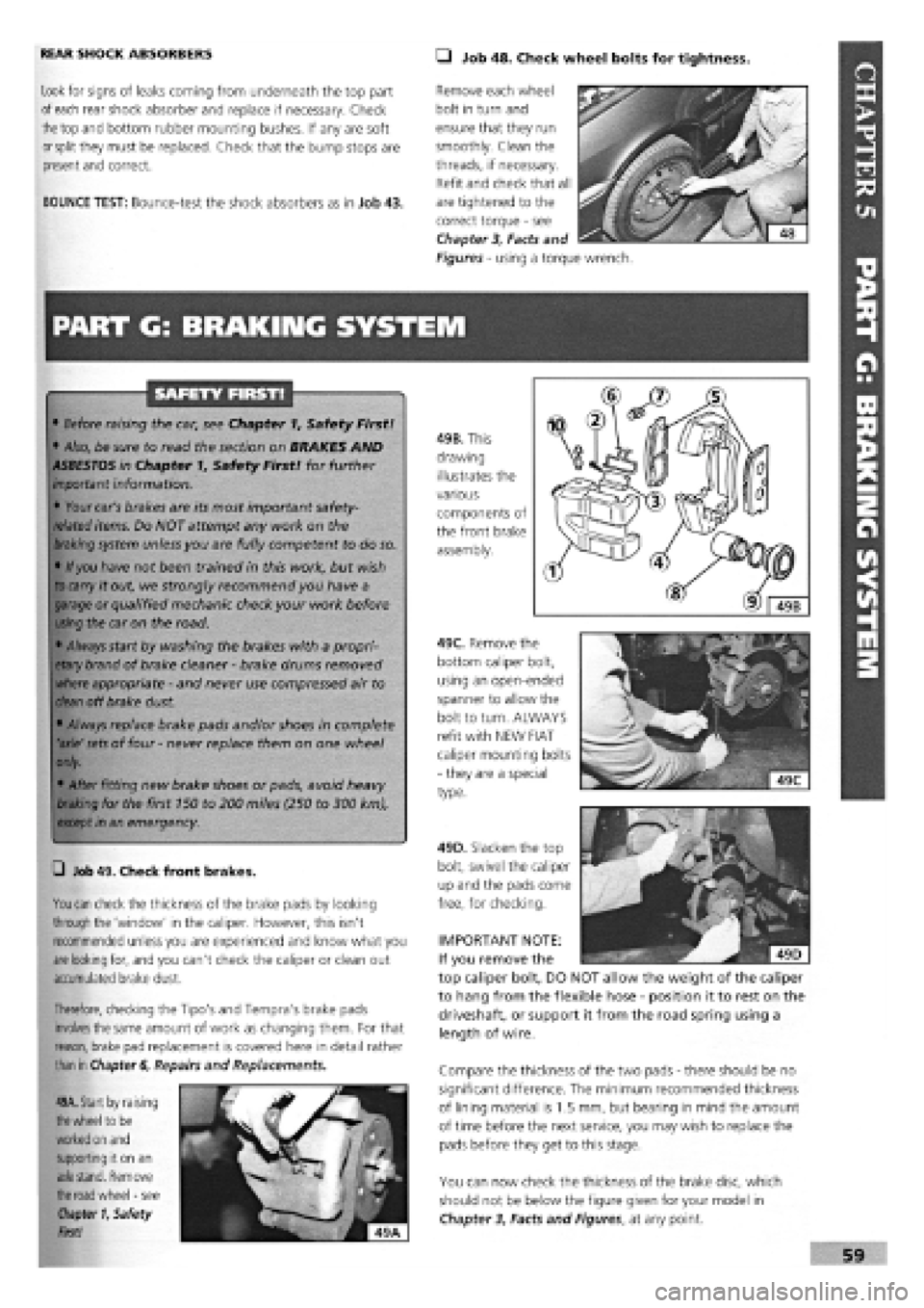
49B. This
drawing
illustrates the
various
components of
the front brake
assembly.
49C. Remove the
bottom caliper bolt,
using an open-ended
spanner to allow the
bolt to turn. ALWAYS
refit with NEW FIAT
caliper mounting bolts
-
they are a special
type.
Therefore,
checking the Tipo's and Tempra's brake pads
involves
the same amount of work as changing them. For that
reason, brake
pad replacement is covered here in detail rather
than in
Chapter
6,
Repairs and Replacements.
49A. Start by raising
the
wheel to
be
worked on and
supporting it on
an
axle stand. Remove
the road wheel
-
see
Chapter
1, Safety
First!
Compare the thickness of the two pads
-
there should be no
significant difference. The minimum recommended thickness
of lining material is 1.5 mm, but bearing in mind the amount
of time before the next service, you may wish to replace the
pads before they get to this stage.
You can now check the thickness of the brake disc, which
should not be below the figure given for your model in
Chapter
3,
Facts and Figures, at any point.
Remove each wheel
bolt in turn and
ensure that they run
smoothly. Clean the
threads, if necessary.
Refit and check that all
are tightened to the
correct torque
-
see
Chapter
3,
Facts and
Figures
-
using a torque wrench.
49D. Slacken the top
bolt, swivel the caliper
up and the pads come
free, for checking.
IMPORTANT NOTE:
If you remove the
top caliper bolt, DO NOT allow the weight of the caliper
to hang from the flexible hose
-
position it to rest on the
driveshaft, or support it from the road spring using a
length of wire.
Page 62 of 171
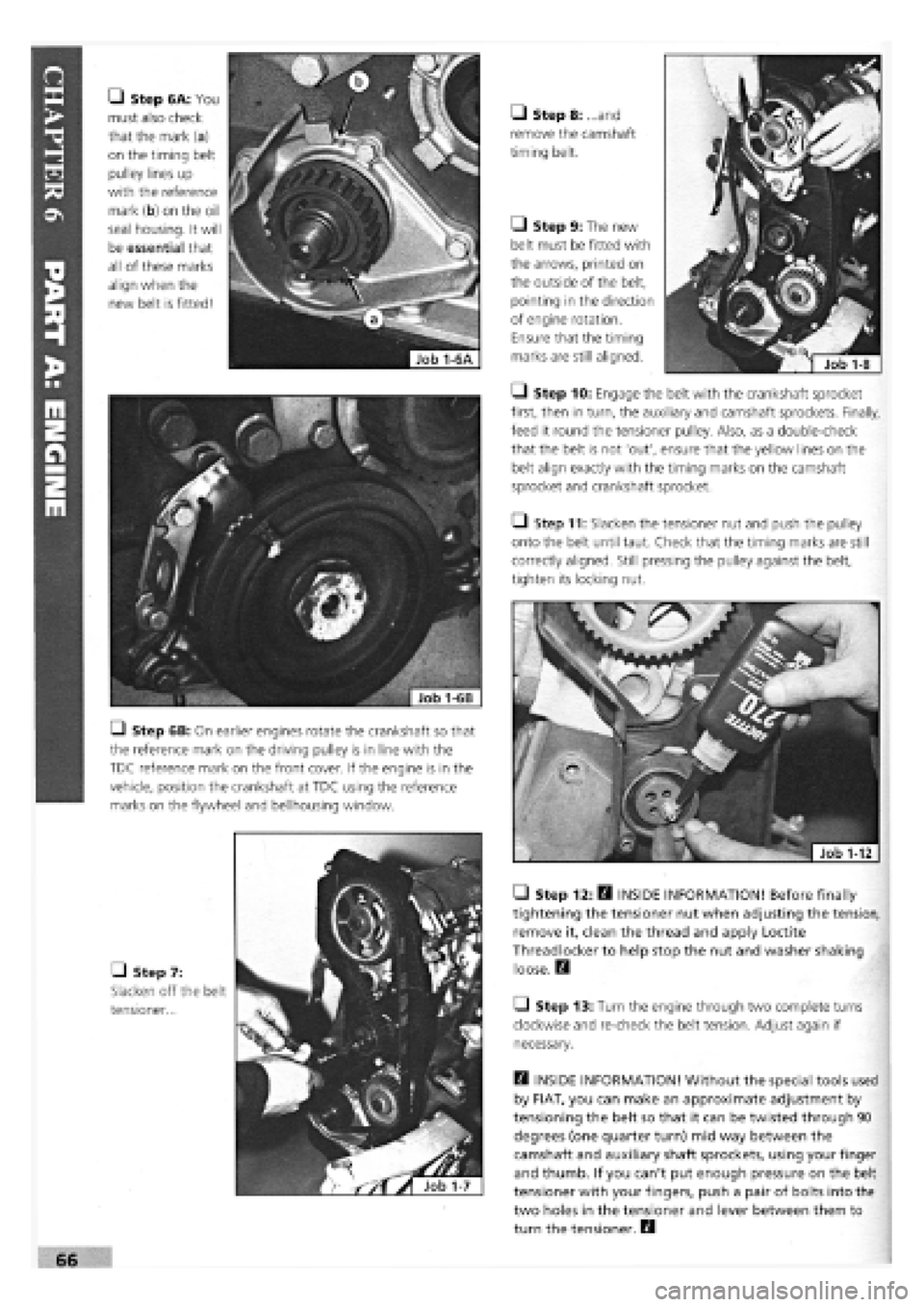
• Step 6A: You
must also check
that the mark (a)
on the timing belt
pulley lines up
with the reference
mark (b) on the oil
seal housing. It will
be essential that
all of these marks
align when the
new belt is fitted!
Q Step 6B: On earlier engines rotate the crankshaft so that
the reference mark on the driving pulley is in line with the
TDC reference mark on the front cover. If the engine is in the
vehicle, position the crankshaft at TDC using the reference
marks on the flywheel and bellhousing window.
• Step 7:
Slacken off the belt
tensioner...
• Step 8: ...and
remove the camshaft
timing belt.
Q Step 9: The new
belt must be fitted with
the arrows, printed on
the outside of the belt,
pointing in the direction
of engine rotation.
Ensure that the timing
marks are still aligned.
• Step 10: Engage the belt with the crankshaft sprocket
first, then in turn, the auxiliary and camshaft sprockets. Finally,
feed it round the tensioner pulley. Also, as a double-check
that the belt is not 'out', ensure that the yellow lines on the
belt align exactly with the timing marks on the camshaft
sprocket and crankshaft sprocket.
Q Step 11: Slacken the tensioner nut and push the pulley
onto the belt until taut. Check that the timing marks are still
correctly aligned. Still pressing the pulley against the belt,
tighten its locking nut.
• Step 12: H INSIDE INFORMATION! Before finally
tightening the tensioner nut when adjusting the tension,
remove it, clean the thread and apply Loctite
Threadlocker to help stop the nut and washer shaking
loose. Q
Q Step 13: Turn the engine through two complete turns
clockwise and re-check the belt tension. Adjust again if
necessary.
Q INSIDE INFORMATION! Without the special tools used
by FIAT, you can make an approximate adjustment by
tensioning the belt so that it can be twisted through 90
degrees (one quarter turn) mid way between the
camshaft and auxiliary shaft sprockets, using your finger
and thumb. If you can't put enough pressure on the belt
tensioner with your fingers, push a pair of bolts into the
two holes in the tensioner and lever between them to
turn the tensioner. B
Page 104 of 171

Job 2. Ignition coil - replacement.
ALL 1.4 MODELS AND 1.6 MODELS UP TO 1993
Q Step 1: Locate the coil (2) next to
the battery.
IMPORTANT NOTE: On 1.6 models
from 1993 with SPI Monomotronic
fuel injection, the high tension coil
is integral with the distributor.
• Step 2: Make sure the ignition is
switched off and disconnect all LT (the
smaller, low tension) wires from the
coil, making note of their locations for
refitting.
• Step 3: Unplug the HT (the
thicker, high tension) lead to the
distributor at the coil end. Undo the
mountings and remove the coil.
• Step 4: Mount the new coil, remake all connections
correctly and firmly.
Job 3. Distributor - removal and
refitting (1.4 litre engine).
FACT FILE: 1.4. LITRE ENGINE
DISTRIBUTOR
This system is of the BREAKERLESS
INDUCTIVE DISCHARGE type (2nd gener-
ation) and employs a distributor looking
much like those used on older cars, still
having an internal centrifugal advance mechanism, a vacuum
advance mechanism (3),
but NO contact breaker
points - an electronic
control module (2)
instead. This means that
once set, the timing
cannot alter through
points gap fluctuation.
Maintenance is also
reduced to a minimum,
the main requirements
being to keep the unit
clean and dry.
l_) Step 1: Locate the distributor (see illustration Job1-2A,
part a) which is mounted on the forward facing side of the
engine block, close to the timing belt cover.
I—] Step 2: Remove the distributor cap and leads.
Q Step 3: Disconnect the (thinner) low tension lead, undo
the distributor base clamp and withdraw the distributor.
Q Step 4: Turn
the engine until
the crankshaft
pulley timing
mark is aligned
with the '0' (TDC)
mark on the
timing belt cover
(a) and the marks
seen through the
timing belt
window (b), also
line up.
• Step S: If the
marks
seen through the window
do not align
-
turn the
engine another complete revolution and they will.
• Step 6: Refit the distributor with the centre of the rotor
contact pointing 180 degrees away from (in other words,
exactly opposite) the reference mark on the distributor dust
cover.
Q Step 7: Refit the distributor cap and remake all connec-
tions. Leave the vacuum pipe disconnected but plug the end
of the pipe.
Q Step 8: Refit the base clamp but leave just loose enough
to allow the distributor to turn.
Q Step 9: Connect a stroboscopic timing light and start the
engine. Run it at between 750 and 850 rpm.
• Step 10:
Rotate the
distributor body
the required
amount in either
direction to align
the pulley timing
mark with the 10
degree BTDC
mark on the
timing belt cover
• Step 11: Remove the timing light, unplug and reconnect
the vacuum pipe.
Job 4. Distributor - removal and
refitting (1.6 litre engine).
FACT FILE: 1.6 LITRE ENGINE
DISTRIBUTOR
The DIGIPLEX 2 ALL ELECTRONIC (2nd
generation) IGNITION system used on the
1.6 litre engine is of advanced design and
requires no maintenance. Because there is no
mechanical wear, the advance curves remain constant during
the life of the unit. Inaccuracies due to wear or vibration are
eliminated. The high spark intensity is constant, even with a
low battery when starting, and at high RPM.
and lock the distributor base clamp.
Page 106 of 171

PART E: ELECTRICAL ARID INSTRUMENTS
PART E: Contents
Job 1. Alternator
-
removal and refitting. Job 10. Rear light cluster
-
replacement.
Job 2. Starter motor
-
removal and refitting. Job 11. Side repeater indicators
-
replacement.
Job 3. Instrument panel
-
removal and refitting. Job 12. Number plate light
-
replacement.
Job 4. Speedometer cable
-
replacement. Job 13. Interior/courtesy light
-
removal and refitting.
Job 5. Windscreen wiper motor
-
replacement. Job 14. Fuel gauge sender unit
-
removal and refitting.
Job 6. Hatchback wiper motor
-
replacement. Job 15. Central locking
-
replacement of components.
Job 7. Windscreen washer pump
-
replacement. Job 16. Electric windows
-
replacement of components.
Job 8. Radio aerial
-
replacement. Job 17. Diesel engines. Glow plugs
-
checking and
Job 9. Headlight cluster
-
replacement. replacement.
Job 1. Alternator - removal
and refitting.
Job 3. Instrument panel -
removal and refitting.
• Step 1: Disconnect the battery earth lead.
Q Step 2: Disconnect all the wires from the back of the
alternator
-
the main output wire is released by undoing its
securing nut. Slacken the bolt securing the inboard end of the
adjustment bar, undo and remove the bolt from the alternator
end of the bar. Slacken the drivebelt and remove it.
Q Step 3: On manual steering cars, unbolt and remove the
adjuster bracket from the cylinder block.
Q Step 4: Release the securing buttons and remove the
engine splash shield on power steering cars.
Q Step 5: Undo the nut from the long through bolt and
note the position of the washers. Support the alternator and
remove the bolt, then withdraw the alternator from the car.
Q Step 6: Refit in reverse order and make sure your
electrical connections are sound. Adjust the drivebelt tension.
See Chapter 5, Servicing Your Car
• Step 1: Disconnect
terminal.
• Step 2: Undo the
screws (arrowed) and
remove the speaker
cover (1).
Job 2. Starter motor - removal
and refitting.
• Step 1: Disconnect the battery earth lead.
• Step 2:
Undo and remove
all the electrical
connections (a)
from the starter
(b) and starter
solenoid (c).
Q Step 4: Refit in reverse order, ensuring that all connec-
tions are sound.
Q Step 5: Raise the instrument panel enough to unplug
the connectors from the rear. Disconnect the speedometer
drive (if non-electronic type) and remove the instrument
panel from the car.
Q Step 6: Refit in the reverse order and be sure that all
connections are properly made.
Job 4. Speedometer cable
replacement.
• Step 1: H INSIDE INFORMATION! The cable comes in
two parts, joined in the middle by a connector (a). Q
• Step 2: Follow Job 3, Steps 1 to 3 Then, lift the
instrument panel
sufficiently so that
you can gain
access to the
cable.
^Jj
Job
4-1
the battery at the negative (earth)
• Step 3: Undo the
exposed screws that
secure the
instrument panel
(arrowed).
• Step 4: Slide
off the screw
cover
(2)
from
the other end of
the instrument
panel and
remove the two
screws found beneath it.
• Step 3:
Undo the three mounting bolts and the wiring harness bracket
from the top bolt and withdraw the starter.
Page 110 of 171
Job 15. Central locking -
replacement off components.
Job 14. Fuel gauge sender unit
removal and refitting.
SAFETY FIRST!
• Carry out this work out of doors, away from sources
of ignition.
• Make the open aperture on top of the fuel tank air
tight as quickly as possible.
• You should carry out this job when the fuel is at a
low level.
VEHICLES WITH ELECTRIC FUEL PUMPS
(NOT ENGINE MOUNTED)
Job 16. Electric windows -
replacement of components.
courtesy light lens and/or panel. The connectors are on
the rear of the unit.
• Step 3: The estate car has a rear courtesy light which is
removed as in Step 1 and 2
LJ Step 4: Refit in the reverse order.
PART A: ELECTRONIC CONTROL UNIT
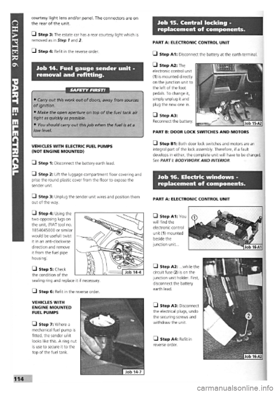
• Step A1: You
will find the
electronic control
unit
(1)
mounted
beside the
junction unit...
PART A: ELECTRONIC CONTROL UNIT
• Step A1: Disconnect the battery at the earth terminal.
• Step A2: The
electronic control unit
(1) is mounted directly
on the junction unit to
the left of the foot
pedals. To change it,
simply unplug it and
plug the new one in.
• Step A3:
Reconnect the battery.
PART B: DOOR LOCK SWITCHES AND MOTORS
• Step B1: Both door lock switches and motors are an
integral part of the lock assembly. Therefore, if a fault
develops in either, the complete unit will have to be changed.
See PARTI: BODYWORK AND INTERIOR
• Step A2: ...while the
circuit fuse (2) is on the
junction unit holder. First,
disconnect the battery
earth lead.
• Step A3: Disconnect
the electrical plugs, undo
the securing screws and
withdraw the unit.
• Step A4: Refit in
reverse order.
Q Step 1: Disconnect the battery earth lead.
Q Step 2: Lift the luggage compartment floor covering and
prise the round plastic cover from the floor to expose the
sender unit.
Q Step 3: Unplug the sender unit wires and position them
out of the way.
• Step 4: Using the
two opposing lugs on
the unit, (FIAT tool no.
1854045000 or similar
would be useful) twist
it in an anti-clockwise
direction and remove
it from the fuel pipe
housing.
C-) Step 6: Refit in the reverse order.
VEHICLES WITH
ENGINE MOUNTED
FUEL PUMPS
• Step 7: Where a
mechanical fuel pump is
fitted, the sender unit
looks like this. A ring nut
is use to secure it to the
top of the fuel tank.
• Step 5: Check
the condition of the
sealing ring and replace it if necessary.
Job 16-A1
Page 111 of 171
Job 17. Diesel engines - Glow
plugs, checking and replacement.
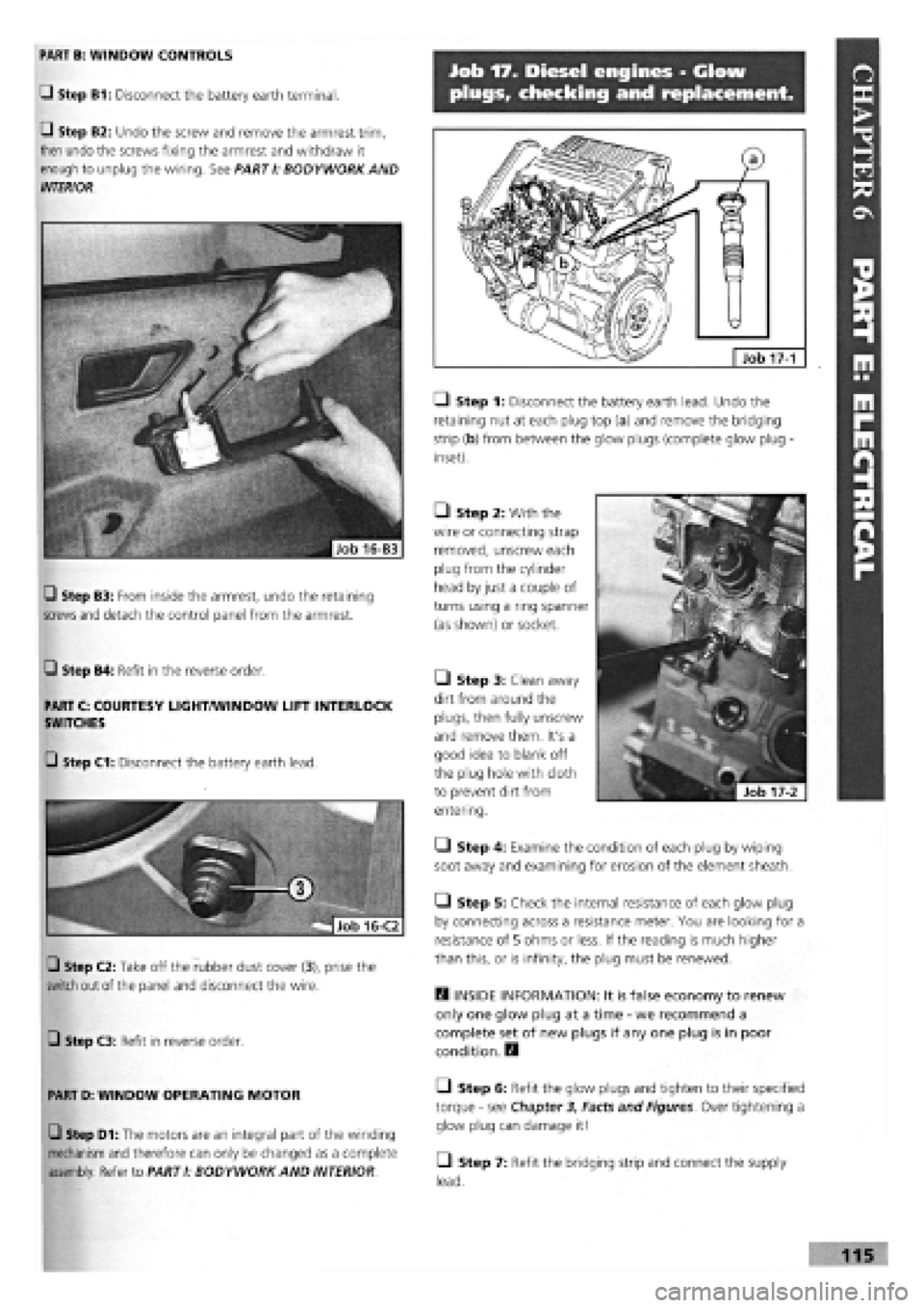
LI Step 1: Disconnect the battery earth lead. Undo the
retaining nut at each plug top (a) and remove the bridging
strip (b) from between the glow plugs (complete glow plug -
inset).
• Step 2: With the
wire or connecting strap
removed, unscrew each
plug from the cylinder
head by just a couple of
turns using a ring spanner
(as shown) or socket.
H INSIDE INFORMATION: It is false economy to renew
only one glow plug at a time
-
we recommend a
complete set of new plugs if any one plug is in poor
condition. E9
• Step 6: Refit the glow plugs and tighten to their specified
torque
-
see Chapter 3, Facts and Figures. Over tightening a
glow plug can damage it!
• Step 7: Refit the bridging strip and connect the supply
lead.
17-1
PART B: WINDOW CONTROLS
Q Step B1: Disconnect the battery earth terminal.
Q Step B2: Undo the screw and remove the armrest trim,
then undo the screws fixing the armrest and withdraw it
enough to unplug the wiring. See PARTI: BODYWORK AND
INTERIOR.
• Step 3: Clean away
dirt from around the
plugs, then fully unscrew
and remove them. It's a
good idea to blank off
the plug hole with cloth
to prevent dirt from
entering.
• Step 4: Examine the condition of each plug by wiping
soot away and examining for erosion of the element sheath.
• Step 5: Check the internal resistance of each glow plug
by connecting across a resistance meter. You are looking for a
resistance of 5 ohms or less. If the reading is much higher
than this, or is infinity, the plug must be renewed.
Q Step B4: Refit in the reverse order.
PART C: COURTESY LIGHT/WINDOW LIFT INTERLOCK
SWITCHES
Q Step C3: Refit in reverse order.
PART D: WINDOW OPERATING MOTOR
Q Step D1: The motors are an integral part of the winding
mechanism and therefore can only be changed as a complete
assembly. Refer to PART I: BODYWORK AND INTERIOR
Q Step B3: From inside the armrest, undo the retaining
screws and
detach the control panel from the armrest.
G Step C1: Disconnect the battery earth lead.
Q Step C2: Take off the rubber dust cover (3), prise the
switch out of the panel and disconnect the wire.
Page 142 of 171
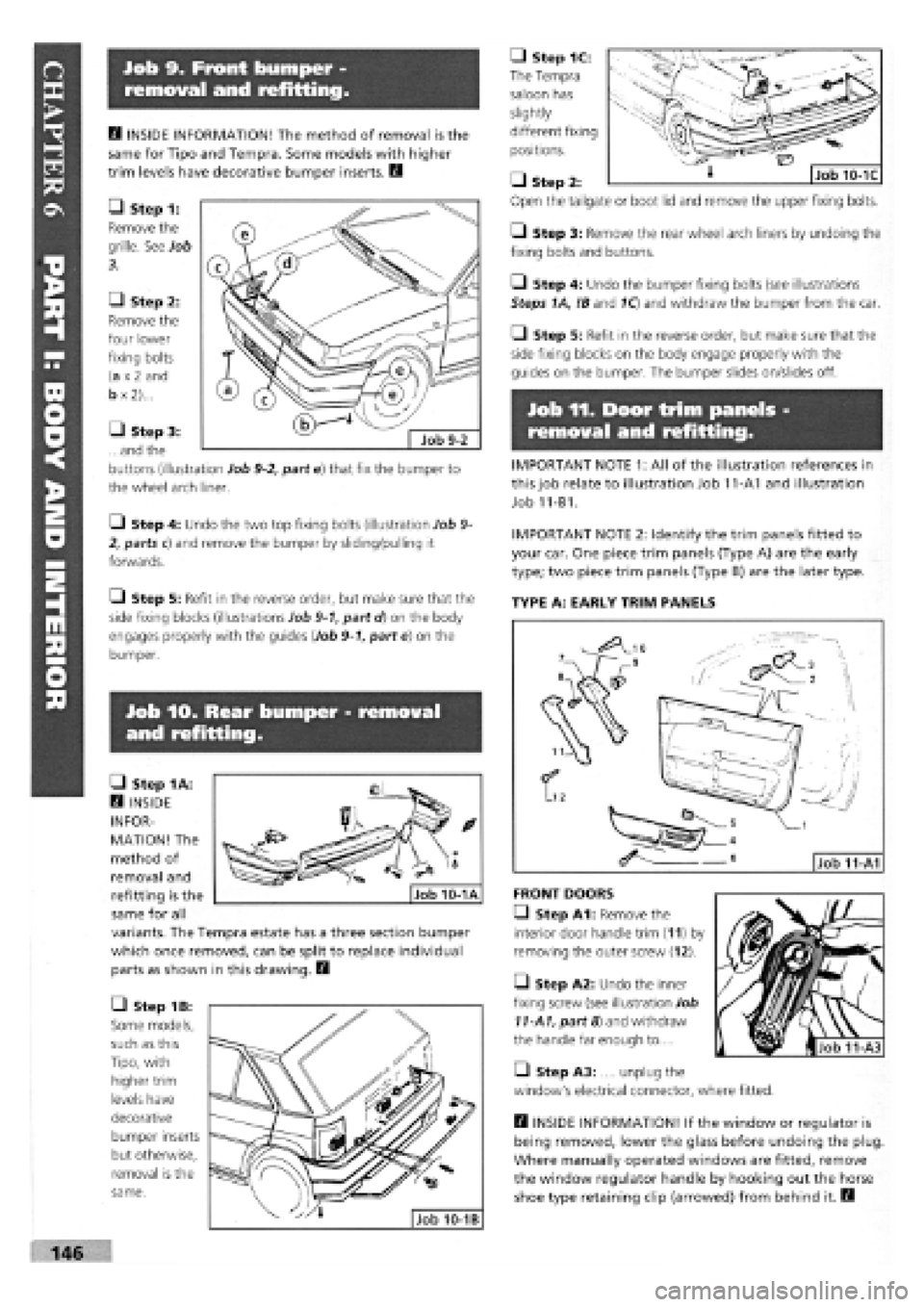
Job 9. Front bumper -
removal and refitting.
• Step 1C:
The Tempra
saloon has
slightly
different fixing
positions.
• Step
Open the
Q Step 3: Remove the rear wheel arch liners by undoing the
fixing bolts and buttons.
• Step 4: Undo the bumper fixing bolts (see illustrations
Steps 1A, !B and 1Q and withdraw the bumper from the car.
• Step 5: Refit in the reverse order, but make sure that the
side fixing blocks on the body engage properly with the
guides on the bumper. The bumper slides on/slides off.
Job 11. Door trim panels -
removal and refitting.
IMPORTANT NOTE 1: All of the illustration references in
this job relate to illustration Job 11-A1 and illustration
Job 11-B1.
IMPORTANT NOTE 2: Identify the trim panels fitted to
your car. One piece trim panels (Type A) are the early
type; two piece trim panels (Type B) are the later type.
TYPE A: EARLY TRIM PANELS
Job lO. Rear bumper - removal
and refitting.
H INSIDE INFORMATION! The method of removal is the
same for Tipo and Tempra. Some models with higher
trim levels have decorative bumper inserts. B
• Step 1:
Remove the
grille. See Job
3.
• Step 2:
Remove the
four lower
fixing bolts
(a
x 2
and
b
x
2)...
• Step 3:
...and the
buttons (illustration Job
9-2,
part e) that fix the bumper to
the wheel arch liner.
Q Step 4: Undo the two top fixing bolts (illustration Job
9-
2, parts c) and remove the bumper by sliding/pulling it
forwards.
Q Step 5: Refit in the reverse order, but make sure that the
side fixing blocks (illustrations Job
9-1,
part d) on the body
engages properly with the guides (Job
9-1,
part e) on the
bumper.
• Step 1A:
Q INSIDE
INFOR-
MATION! The
method of
removal and
refitting is the
same for all
variants. The Tempra estate has a three section bumper
which once removed, can be split to replace individual
parts as shown in this drawing. B
• Step 1B:
Some models,
such as this
Tipo, with
higher trim
levels have
decorative
bumper inserts
but otherwise,
removal is the
same.
FRONT DOORS
• Step A1: Remove the
interior door handle trim (11) by
removing the outer screw (12).
• Step A2: Undo the inner
fixing screw (see illustration Job
11-A1,
part 8) and withdraw
the handle far enough to....
• Step A3: .... unplug the
window's electrical connector, where fitted.
B INSIDE INFORMATION! If the window or regulator is
being removed, lower the glass before undoing the plug
Where manually operated windows are fitted, remove
the window regulator handle by hooking out the horse
shoe type retaining clip (arrowed) from behind it. B
2:
tailgate or boot lid and remove the upper fixing bolts.
MMBBMHHi 146
Page 143 of 171

Job 12. Door components,
removal and replacement.
Q Step B1: Undo the four screws
(6)
and remove the door
pocket (5).
Q Step B2: Carefully lever off the door handle trim (see illus-
tration Job 11-B1, part 11).
Q Step B3: Undo the three screws (11-B1, part 12
-
positions
arrowed) and withdraw the handle (11-B1, part 10) enough to....
• Step A4:
Carefully prise out the
escutcheon plate and
twist it in the direction
shown by the arrow to
allow it to be
withdrawn over the
opening lever and
removed.
• Step A5:
Unscrew the six
screws (illustration
Job 11-A1, part 6)
and remove the door
pocket (Job 11-A1,
part 4).
• Step A6:
Unscrew and remove
the internal locking
button (arrowed) and
remove the trim panel
by carefully levering out the door retaining studs with a flat
bladed tool (preferably two-pronged) to fit either side of the
shoulder of part 2, part 3 remaining in the door frame. Care is
needed here to locate each retaining stud and avoid damage
when disconnecting part 2 from part 3.
H INSIDE INFORMATION! Avoid pulling the door trim off
with your hands and tearing the trim next to the studs. H
C_) Step A7: Refit in the reverse order of removal, banging
each retaining stud carefully home with the flat of your hand.
REAR DOORS
Q Step A8: Follow the instructions for the front door, but
ignore those for the door pocket and window switch.
TYPE B: LATER TRIM PANELS.
FRONT DOORS
• Step B6: Remove the door trim as described in Step A6
and Step A7, removing the upper trim (Job 11-B1, part 2) in
a similar way.
REAR DOORS
• Step B7: Follow the instructions for the front door, but
ignore those for the door pocket and window switch.
the six bolts and
nuts (arrowed) fixing the subframe to the door.
H INSIDE INFORMATION! There are two types of door
shell. The early type has a subframe behind the trim
panel which can be removed complete with the window
regulator and door lock, or just the regulator. The later
type has a fixed inner panel and the components are
removed individually. B
PART A : EARLY FRONT DOORS
• Step A1:
Lower the window
fully and remove
the door trim
panel. See Job 11,
Type A.
• Step A2: Peel
off the transparent
covering from the
door panel and
keep it in a dust
free place so that it
will re-stick easily
when refitted.
• Step A3:
Disconnect the lock
control rod and the
door opening rod
(both arrowed).
• Step A4:
Undo and remove
• Step B4:
...disconnect the
electric windows
control where fitted
(arrowed).
• Step B5:
Carefully prise out
the escutcheon plate
(see illustration Job
11-A4) and twist it
in the direction
shown by the arrow to allow it to be withdrawn over the
opening lever and removed.