Page 224 of 962
BAa7
1 IId916156
1. Drive housing cover
2.Drive bushing3.Drive housing
4.Armature ring
5. Armature stop ring6.Over-running clutch7. Pinion drive lever
8.Magnetic switch
9. Commutator end cover10.Brush spring11.Brush holder12.Brush
13.Washer
14. Commutator end bushing18.Armature
16. Starting motor yoke
A : Hold-in coilB : Pull-in coil
9-3
Page 227 of 962
9-5. DISASSEMBLY
NOTE:
Before disassembling starting motor, be sure to
put match marks at two tocations ( @ and @I )
as shown in the figure below so that any possible
mistakes can be avoided.
/Commutator endcover
Fig. 95
1) Remove nut securing the end of field coil
lead to terminal on the head of magnetic
switch.
Fig. 9-6
2) Take off magnetic switch @ from starting
motor body by removing two mounting
screws.
3) Loosen 2 bolts and 2 screws to remove
commutator end cover.
4) Separate drive housing and armature from
yoke.
Fig. 9-8
5) Draw brushes out of holder.
Fig. 49
6) Draw off over running clutch, as follows:
(1)
(2)
Draw stop ring @ toward clutch side.
Remove armature ring @ and slide off
clutch.
r;)(‘lutch Pinion
Fig. 910
9-6
Page 327 of 962
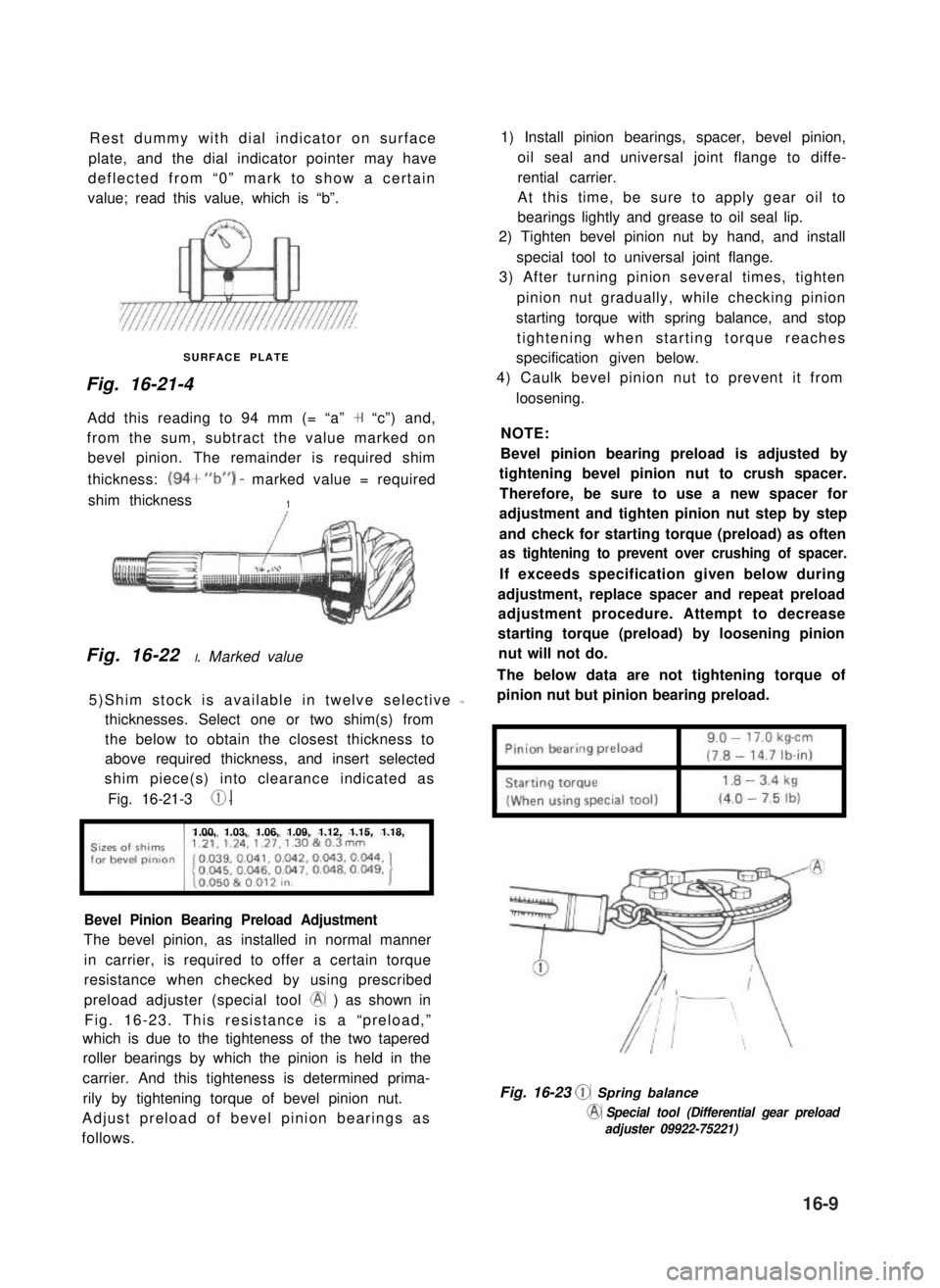
Rest dummy with dial indicator on surface
plate, and the dial indicator pointer may have
deflected from “0” mark to show a certain
value; read this value, which is “b”.
SURFACE PLATE
Fig. 16-21-4
Add this reading to 94 mm (= “a” + “c”) and,
from the sum, subtract the value marked on
bevel pinion. The remainder is required shim
thickness: (94+“b”) - marked value = required
shim thickness1
Fig. 16-22 I. Marked value
5)Shim stock is available in twelve selective L
thicknesses. Select one or two shim(s) from
the below to obtain the closest thickness to
above required thickness, and insert selected
shim piece(s) into clearance indicated as
Fig. 16-21-3 0.
1.00, 1.03, 1.06, 1.09, 1.12, 1.15, 1.18,
Bevel Pinion Bearing Preload Adjustment
The bevel pinion, as installed in normal manner
in carrier, is required to offer a certain torque
resistance when checked by using prescribed
preload adjuster (special tool @ ) as shown in
Fig. 16-23. This resistance is a “preload,”
which is due to the tighteness of the two tapered
roller bearings by which the pinion is held in the
carrier. And this tighteness is determined prima-
rily by tightening torque of bevel pinion nut.
Adjust preload of bevel pinion bearings as
follows.
1) Install pinion bearings, spacer, bevel pinion,
oil seal and universal joint flange to diffe-
rential carrier.
At this time, be sure to apply gear oil to
bearings lightly and grease to oil seal lip.
2) Tighten bevel pinion nut by hand, and install
special tool to universal joint flange.
3) After turning pinion several times, tighten
pinion nut gradually, while checking pinion
starting torque with spring balance, and stop
tightening when starting torque reaches
specification given below.
4) Caulk bevel pinion nut to prevent it from
loosening.
NOTE:
Bevel pinion bearing preload is adjusted by
tightening bevel pinion nut to crush spacer.
Therefore, be sure to use a new spacer for
adjustment and tighten pinion nut step by step
and check for starting torque (preload) as often
as tightening to prevent over crushing of spacer.
If exceeds specification given below during
adjustment, replace spacer and repeat preload
adjustment procedure. Attempt to decrease
starting torque (preload) by loosening pinion
nut will not do.
The below data are not tightening torque of
pinion nut but pinion bearing preload.
Fig. 16-23 @ Spring balance
@ Special tool (Differential gear preload
adjuster 09922-75221)
16-9
Page 405 of 962
Inspection for Front Brake After installing
Mount tires and make certain that they rotate
smoothly, with a force of less than 3.0 kg (6.6
lb).
NOTE:
For the above check, the following must be
observed.
1) Jack up front wheels, both right and left,
off the ground.
2) Set free wheeling hubs of both right and left
wheels to “LOCK”, if equipped.
3) Shift transfer shift lever to 2H (rear wheel)
position.
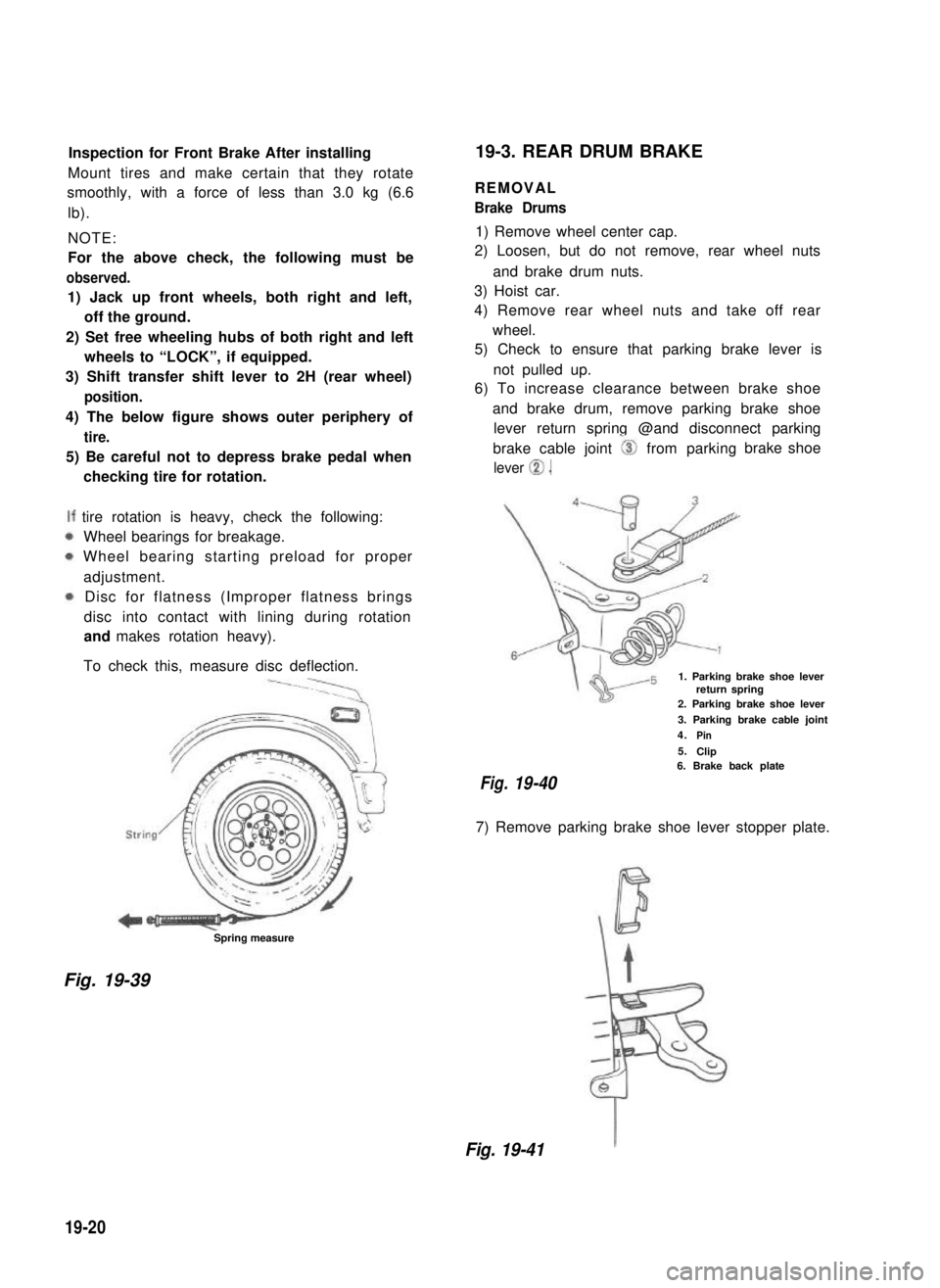
4) The below figure shows outer periphery of
tire.
5) Be careful not to depress brake pedal when
checking tire for rotation.
tire rotation is heavy, check the following:
Wheel bearings for breakage.
Wheel bearing starting preload for proper
adjustment.
Disc for flatness (Improper flatness brings
disc into contact with lining during rotation
and makes rotation heavy).
To check this, measure disc deflection.
Spring measure
19-3. REAR DRUM BRAKE
REMOVAL
Brake Drums
1) Remove wheel center cap.
2) Loosen, but do not remove, rear wheel nuts
and brake drum nuts.
3) Hoist car.
4) Remove rear wheel nuts and take off rear
wheel.
5) Check to ensure that parking brake lever is
not pulled up.
6) To increase clearance between brake shoe
and brake drum, remove parking brake shoe
lever return spring @and disconnect parking
brake cable joint 0 from parking
lever 0.
brake shoe
1. Parking brake shoe leverreturn spring2. Parking brake shoe lever
3. Parking brake cable joint
4.Pin
5.Clip6. Brake back plate
Fig.19-40
7) Remove parking brake shoe lever stopper plate.
Fig. 19-39
Fig. 19-41
19-20
Page 428 of 962
BRAKE PEDAL FREE HEIGHT ADJUSTMENT
Brake pedal height is normal if brake pedal is
as high as clutch pedal.
1) When booster push rod clevis has been
reinstalled, it is important that measurement
between booster mounting surface (with a
gasket attached) and the center of clevis
pin hole is adjusted within 125.5 mm -
126.5 mm (4.94 - 4.98 in.). (See page
19-37.)
2) When stop light switch has been removed,
refer to the following STOP LIGHT SWITCH
ADJUSTMENT for proper installation.
The services in above steps 1) and 2) may
affect brake pedal height.
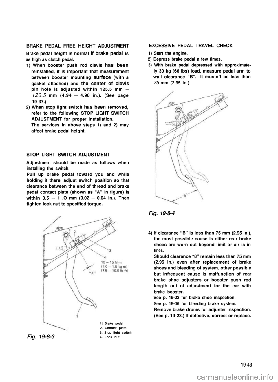
STOP LIGHT SWITCH ADJUSTMENT
Adjustment should be made as follows when
installing the switch.
Pull up brake pedal toward you and while
holding it there, adjust switch position so that
clearance between the end of thread and brake
pedal contact plate (shown as “A” in figure) is
within 0.5 -1 .O mm (0.02 - 0.04 in.). Then
tighten lock nut to specified torque.
1. Brake pedal
2. Contact plate
3. Stop light switch4. Lock nut
EXCESSIVE PEDAL TRAVEL CHECK
1) Start the engine.
2) Depress brake pedal a few times.
3) With brake pedal depressed with approximate-
ly 30 kg (66 Ibs) load, measure pedal arm to
wall clearance “B”.It mustn’t be less than
75 mm (2.95 in.).
Fig. 19-8-4
4) If clearance “B” is less than 75 mm (2.95 in.),
the most possible cause is either rear brake
shoes are worn out beyond limit or air is in
lines.
Should clearance “8” remain less than 75 mm
(2.95 in.) even after replacement of brake
shoes and bleeding of system, other possible
but infrequent cause is malfunction of rear
brake shoe adjusters or booster push rod
length out of adjustment for the car with
brake booster.
See p. 19-22 for brake shoe inspection.
See p. 19-46 for bleeding brake system.
Remove brake drums for adjuster inspection.
(See p. 19-23.) If defective, correct or replace.
Fig. 19-8-3
19-43
Page 432 of 962
5) Repeat this operation until there are no more
air bubbles in hydraulic line.
6) When bubbles stop, depress and hold brake
pedal and tighten bleeder plug.
7) Then attach bleeder plug cap.
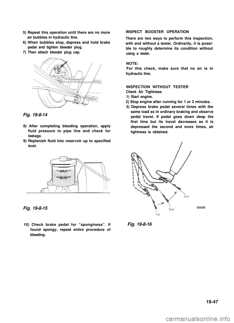
Fig. 19-8-14
8) After completing bleeding operation, apply
fluid pressure to pipe line and check for
leakage.
9) Replenish fluid into reservoir up to specified
level.
Fig. 19-8-15
INSPECT BOOSTER OPERATION
There are two ways to perform this inspection,
with and without a tester. Ordinarily, it is possi-
ble to roughly determine its condition without
using a tester.
NOTE:
For this check, make sure that no air is in
hydraulic line.
INSPECTION WITHOUT TESTER
Check Air Tightness
1) Start engine.
2) Stop engine after running for 1 or 2 minutes.
3) Depress brake pedal several times with the
same load as in ordinary braking and observe
pedal travel. If pedal goes down deep the
first time but its travel decreases as it is
depressed the second and more times, air
tightness is obtained.
GOOD
10) Check brake pedal for “sponginess”. If
’ found spongy, repeat entire procedure of
bleeding.
Fig. 19-8-16
19-47
Page 433 of 962
4) If pedal travel doesn’t change, air tightness
isn’t obtained.
\1 St, 2nd. 3rd
NO GOOD
Fig. 19-8-17
NOTE:
If defective, inspect vacuum lines and sealing
parts, and replace any faulty part.
When this has been done, repeat the entire test!
Check Operation
1) With engine stopped, depress brake pedal
several times with the same load and make
sure that pedal travel doesn’t change.
Fig. 19-8-19 \
Check Air Tightness Under Load
1) With engine running, depress brake pedal.
Then stop engine while holding brake pedal
depressed.
-Hold
Fig. 19-8-20
2) Hold brake pedal depressed for 30 seconds.
If pedal height does n.ot change, condition
is good. But it isn’t if pedal rises.
Fig. 19-8-18
2) Start engine while depressing brake pedal. If
pedal travel increases a little, operation is
satisfactory. But no change in pedal travel
indicates malfunction.
Fig. 19-8-21Hold
19-48
Page 458 of 962
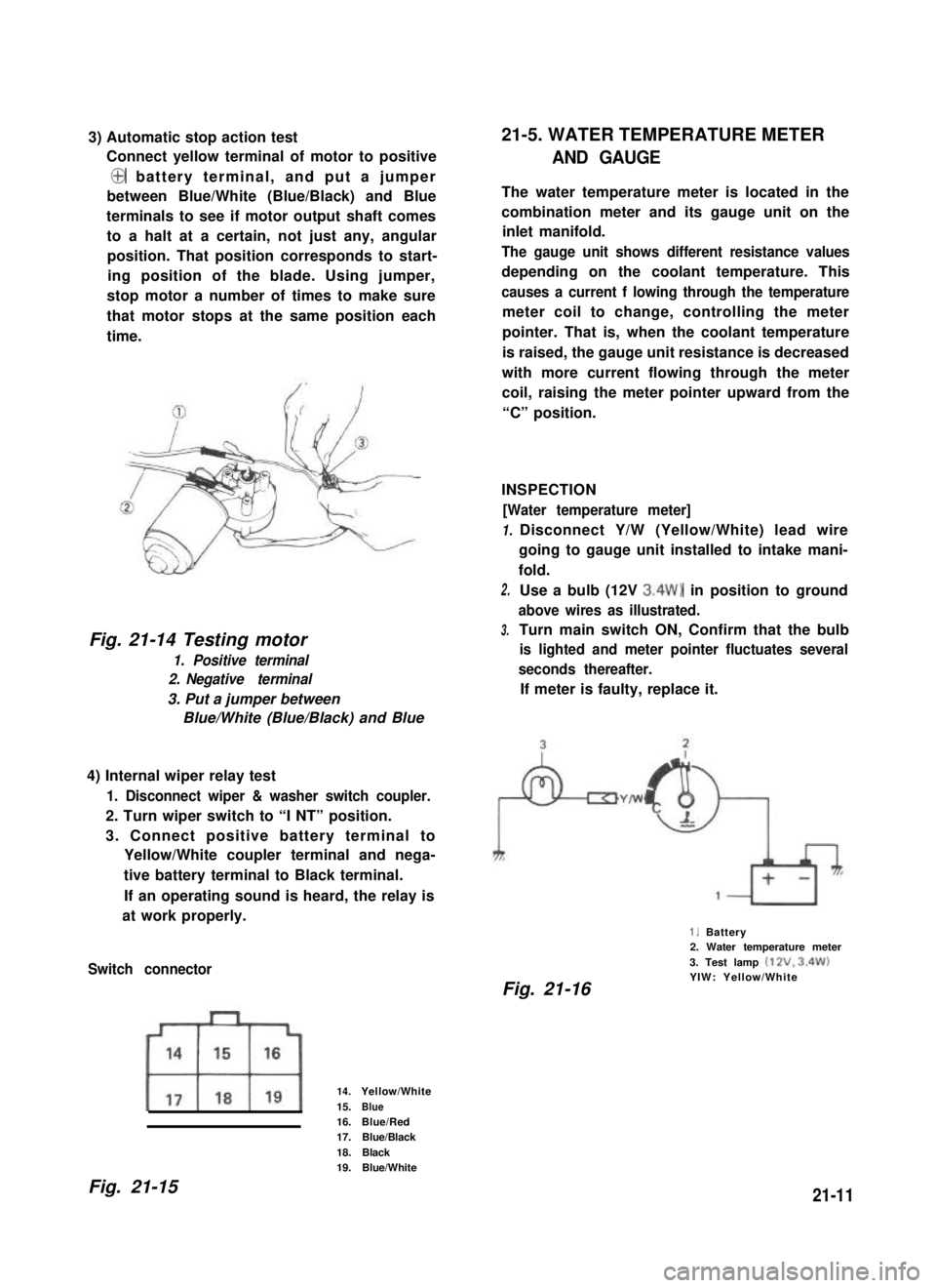
3) Automatic stop action test
Connect yellow terminal of motor to positive
@ battery terminal, and put a jumper
between Blue/White (Blue/Black) and Blue
terminals to see if motor output shaft comes
to a halt at a certain, not just any, angular
position. That position corresponds to start-
ing position of the blade. Using jumper,
stop motor a number of times to make sure
that motor stops at the same position each
time.
Fig. 21-14 Testing motor
1. Positive terminal
2. Negative terminal
3. Put a jumper between
Blue/White (Blue/Black) and Blue
4) Internal wiper relay test
1. Disconnect wiper & washer switch coupler.
2. Turn wiper switch to “I NT” position.
3. Connect positive battery terminal to
Yellow/White coupler terminal and nega-
tive battery terminal to Black terminal.
If an operating sound is heard, the relay is
at work properly.
Switch connector
14.Yellow/White
15.Blue16.Blue/Red17.Blue/Black
18.Black19.Blue/White
21-5. WATER TEMPERATURE METER
AND GAUGE
The water temperature meter is located in the
combination meter and its gauge unit on the
inlet manifold.
The gauge unit shows different resistance values
depending on the coolant temperature. This
causes a current f lowing through the temperature
meter coil to change, controlling the meter
pointer. That is, when the coolant temperature
is raised, the gauge unit resistance is decreased
with more current flowing through the meter
coil, raising the meter pointer upward from the
“C” position.
INSPECTION
[Water temperature meter]
1.
2.
3.
Disconnect Y/W (Yellow/White) lead wire
going to gauge unit installed to intake mani-
fold.
Use a bulb (12V 3.4W) in position to ground
above wires as illustrated.
Turn main switch ON, Confirm that the bulb
is lighted and meter pointer fluctuates several
seconds thereafter.
If meter is faulty, replace it.
1. Battery2. Water temperature meter
3. Test lamp (12V. 3.4W)YIW: Yellow/WhiteFig. 21-16
Fig. 21-1521-11