1987 SUZUKI GRAND VITARA engine coolant
[x] Cancel search: engine coolantPage 127 of 962
REMOVAL AND INSTALLATION
Removal and installation of carburetor
place where no fire is used around.
Removal
1) Disconnect negative battery cord from
battery.
2) Drain coolant.
WARNING:
To help avoid the danger of being burned,
do not remove the drain plug and the
radiator cap while the engine and radiator
are still hot. Scalding fluid and steam can
be blown out under pressure if the plug
and cap are taken off too soon.
3) Remove air intake case from carburetor.
4) Disconnect micro switches, switch vent sole-
noid valve, fuel cut solenoid valve and MCSV
lead wires at their couplers.
5) Disconnect VSV coupler from VSV.
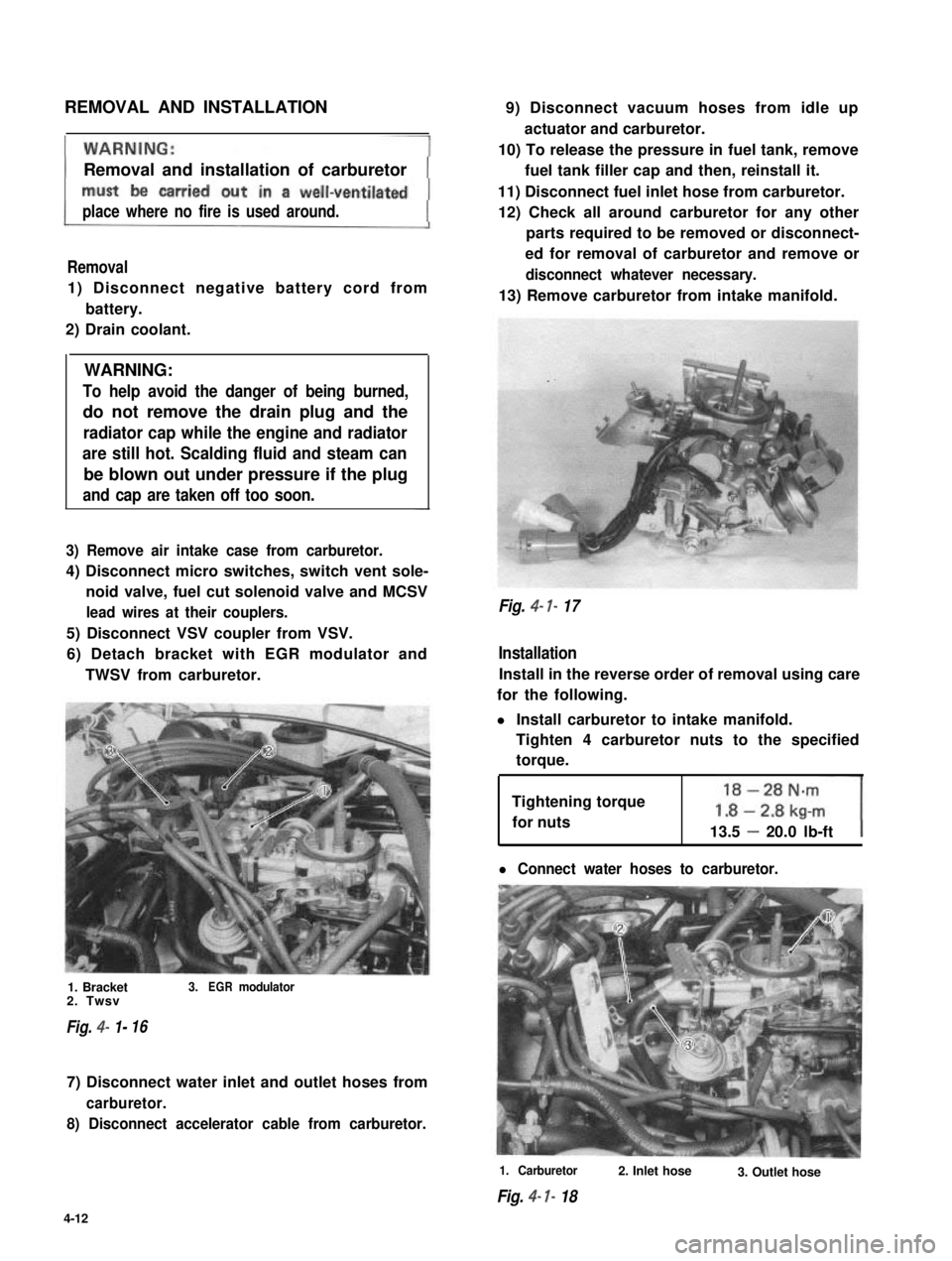
6) Detach bracket with EGR modulator and
TWSV from carburetor.
1. Bracket3.EGRmodulator2. Twsv
Fig. 4- 1-16
7) Disconnect water inlet and outlet hoses from
carburetor.
8) Disconnect accelerator cable from carburetor.
9) Disconnect vacuum hoses from idle up
actuator and carburetor.
10) To release the pressure in fuel tank, remove
fuel tank filler cap and then, reinstall it.
11) Disconnect fuel inlet hose from carburetor.
12) Check all around carburetor for any other
parts required to be removed or disconnect-
ed for removal of carburetor and remove or
disconnect whatever necessary.
13) Remove carburetor from intake manifold.
Fig. 4- 7- 17
Installation
Install in the reverse order of removal using care
for the following.
l Install carburetor to intake manifold.
Tighten 4 carburetor nuts to the specified
torque.
Tightening torque
for nuts13.5 - 20.0 lb-ft
l Connect water hoses to carburetor.
1. Carburetor
Fig. 4- I- 18
2. Inlet hose3. Outlet hose
4-12
Page 134 of 962
16) Clamp wire harness securely.MAINTENANCE SERVICES
Fig. 4- l-39
1. Clamp
17) Remove the pin installed before disassemb-
ly (to lock fast idle cam).
Fig. 4- l-40
Before checking or adjusting the carburetor as
the cause of poor engine performance or rough
idle, check the followings for malconditions.
Ignition system including distributor, timing,
spark plugs and wires.
Air cleaner including thermostatically control-
led air cleaner system.
Evaporative emission control system.
PCV system.
EG R valve.
Engine compression.
Also, check the intake manifold, carburetor and
vacuum hoses for leakage.
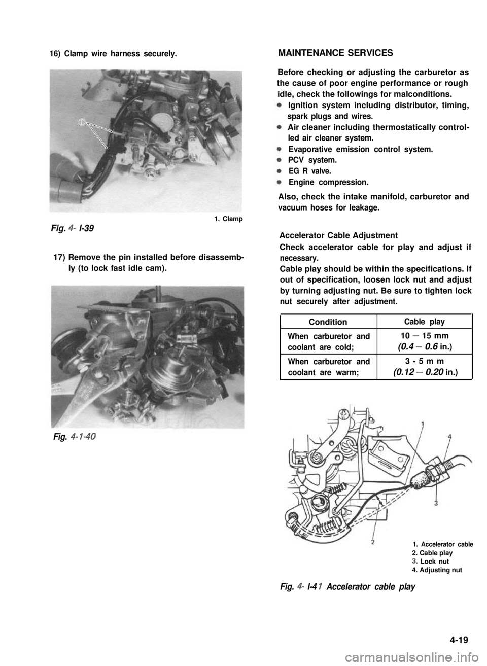
Accelerator Cable Adjustment
Check accelerator cable for play and adjust if
necessary.
Cable play should be within the specifications. If
out of specification, loosen lock nut and adjust
by turning adjusting nut. Be sure to tighten lock
nut securely after adjustment.
Condition
When carburetor and
coolant are cold;
When carburetor and
coolant are warm;
Cable play
10 - 15 mm
(0.4 - 0.6 in.)
3-5mm
(0.12 - 0.20 in.)
1. Accelerator cable
2. Cable play
3. Lock nut
4. Adjusting nut
Fig. 4- l-4 1 Accelerator cable play
4-19
Page 137 of 962
![SUZUKI GRAND VITARA 1987 Service Repair Manual Ambient temperatureClearance
Fig. 4-l-47
Choke Adjustment
Perform following check and adjustments with
air intake case removed when engine is cold.
[Choke valve]
1) Check choke valve for smooth moveme](/manual-img/20/57437/w960_57437-136.png "SUZUKI GRAND VITARA 1987 Service Repair Manual Ambient temperatureClearance
Fig. 4-l-47
Choke Adjustment
Perform following check and adjustments with
air intake case removed when engine is cold.
[Choke valve]
1) Check choke valve for smooth moveme")
Ambient temperatureClearance
Fig. 4-l-47
Choke Adjustment
Perform following check and adjustments with
air intake case removed when engine is cold.
[Choke valve]
1) Check choke valve for smooth movement by
pushing it with a finger.
Fig. 4-l-48 Choke valve
2) Make sure that choke valve is closed almost
completely when ambient temperature is
below 25°C (77” F) and engine is cold.
3) Check to ensure that choke valve to carbure-
tor bore clearance is within following specifi-
cations when engine is cool.
I.6 mmC&n*?.:.. \
NOTE:
As ambient temperature or engine coolant
temperature rises high, clearance increases.
1. Choke valve2. Thickness gauge
Fig. 4- 149 Choke valve to carbure tar bore
clearance
4) If clearance is found excessively large or
small in the above check, check strangler
spring, choke piston and each link in choke
system for smooth operation. Lubricate
choke valve shaft and each link with spray
lubricant if necessary.
Fig. 4-l-50
4-22
Page 161 of 962
![SUZUKI GRAND VITARA 1987 Service Repair Manual COMPUTER CONTROLLED EMISSION CONTROL SYSTEM
[Feed back system]
A prime purpose of this system is to maintain a controlled air fuel ratio, allowing the catalyst to reduce
oxides of nitrogen, hydrocarbo](/manual-img/20/57437/w960_57437-160.png "SUZUKI GRAND VITARA 1987 Service Repair Manual COMPUTER CONTROLLED EMISSION CONTROL SYSTEM
[Feed back system]
A prime purpose of this system is to maintain a controlled air fuel ratio, allowing the catalyst to reduce
oxides of nitrogen, hydrocarbo")
COMPUTER CONTROLLED EMISSION CONTROL SYSTEM
[Feed back system]
A prime purpose of this system is to maintain a controlled air fuel ratio, allowing the catalyst to reduce
oxides of nitrogen, hydrocarbons, carbon monoxide and to improve fuel economy simultaneously.
The electronic control module (ECM) and the oxygen sensor are provided in this system.
The oxygen sensor mounted on the exhaust manifold monitors the exhaust gas air fuel ratio and signals to
the ECM.
The ECM processes the oxygen sensor signal and controls carburetor air fuel ratio by the operation of the
mixture control solenoid in the carburetor.
Thus the signal of the exhaust gas air fuel ratio sensed by the oxygen sensor is fed back to ECM and the
carburetor air fuel ratio is controlled.
[Electronic control module (ECM)]
The ECM controls the fuel cut system, idle-up system, bowl vent system, EGR system and secondary
throttle valve system, as well as the feed back system. The ECM is located under the glove box of the
instrument main panel. Refer to Fig. 5-l -9.
I1
* Engine coolant
temperature
* Engine speed
-Electronic
controlmodule
I I
* Throttle positiont(Micro Switches)
I I I\-
* Fuel cut solenoid valve
-44
* Engine room
- * Vent solenoid valvetempe.rature
* Idle-up actuator (TWSV)* Electric load
* Secondary throttle valve (VSV) , _ ~
r* Mixture control
solenoid valve
* Barometric
pressure
+ ECM supply
voltage
* Gear position
Fig. 5-l-8Computer con trolled emissioncon trot s ys tern
5- 10
Page 162 of 962
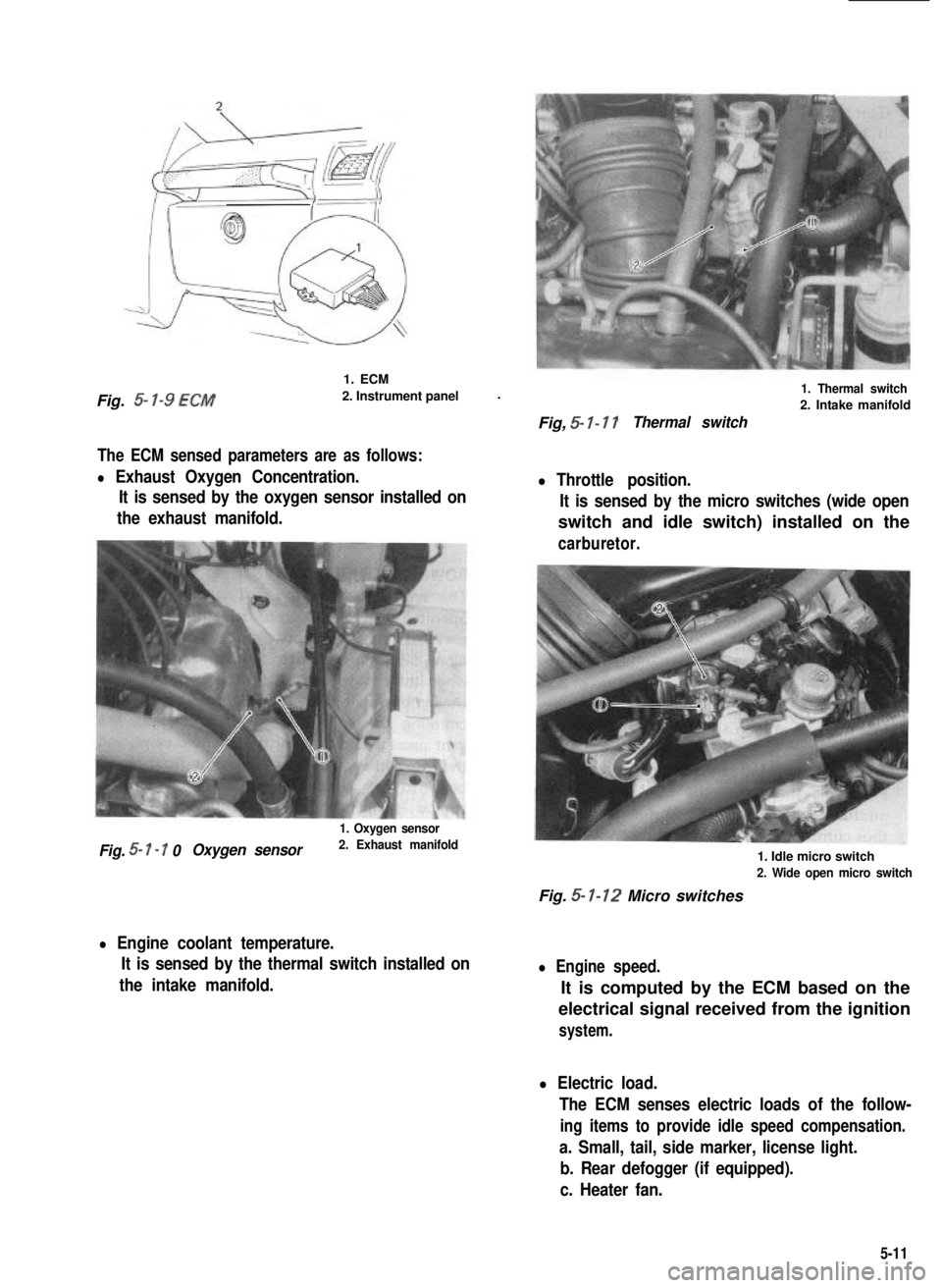
Fig. 5- l-9 ECM
1. ECM
2. Instrument panel.
The ECM sensed parameters are as follows:
l Exhaust Oxygen Concentration.
It is sensed by the oxygen sensor installed on
the exhaust manifold.
1. Oxygen sensor
Fig. 5- I - 7 0Oxygen sensor2. Exhaust manifold
l Engine coolant temperature.
It is sensed by the thermal switch installed on
the intake manifold.
1. Thermal switch
2. Intake manifold
Fig, 5- I- 17Thermal switch
l Throttle position.
It is sensed by the micro switches (wide open
switch and idle switch) installed on the
carburetor.
1. Idle micro switch
2. Wide open micro switch
Fig. 5- 1-12 Micro switches
l Engine speed.
It is computed by the ECM based on the
electrical signal received from the ignition
system.
l Electric load.
The ECM senses electric loads of the follow-
ing items to provide idle speed compensation.
a. Small, tail, side marker, license light.
b. Rear defogger (if equipped).
c. Heater fan.
5-11
Page 164 of 962
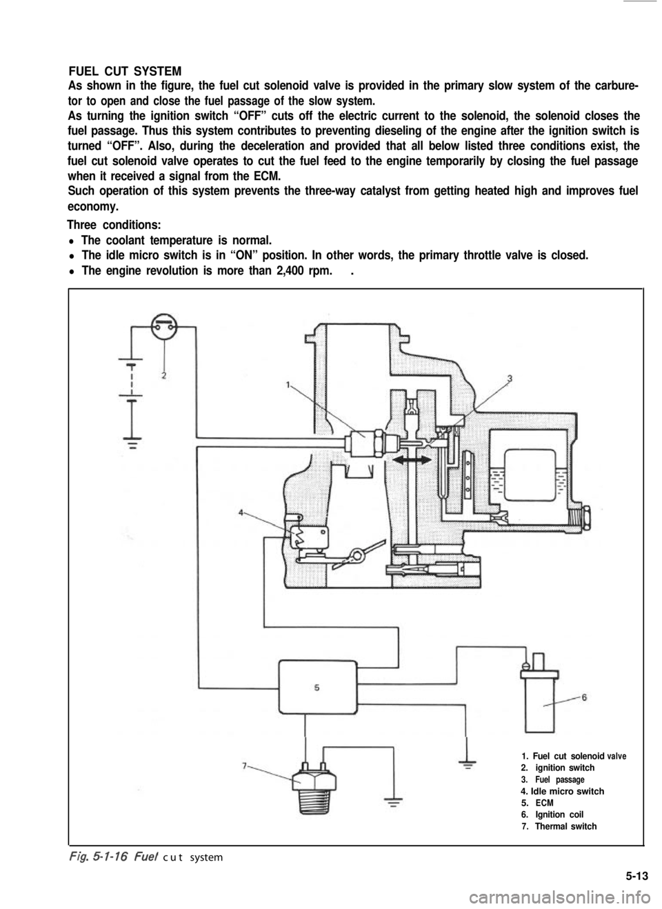
FUEL CUT SYSTEM
As shown in the figure, the fuel cut solenoid valve is provided in the primary slow system of the carbure-
tor to open and close the fuel passage of the slow system.
As turning the ignition switch “OFF” cuts off the electric current to the solenoid, the solenoid closes the
fuel passage. Thus this system contributes to preventing dieseling of the engine after the ignition switch is
turned “OFF”. Also, during the deceleration and provided that all below listed three conditions exist, the
fuel cut solenoid valve operates to cut the fuel feed to the engine temporarily by closing the fuel passage
when it received a signal from the ECM.
Such operation of this system prevents the three-way catalyst from getting heated high and improves fuel
economy.
Three conditions:
l The coolant temperature is normal.
l The idle micro switch is in “ON” position. In other words, the primary throttle valve is closed.
l The engine revolution is more than 2,400 rpm..
1. Fuel cut solenoid
2.ignition switch
3.Fuel passage
4. Idle micro switch
5.ECM
6.Ignition coil
7.Thermal switch
valve
-. .t/g. cut system
5-13
Page 183 of 962
![SUZUKI GRAND VITARA 1987 Service Repair Manual [Checking sensors and their lead wires]
The sensors constituting the feed back system are; wide open micro switch, idle micro switch, thermal
switch, high altitude compensator, thermal engine room swi](/manual-img/20/57437/w960_57437-182.png "SUZUKI GRAND VITARA 1987 Service Repair Manual [Checking sensors and their lead wires]
The sensors constituting the feed back system are; wide open micro switch, idle micro switch, thermal
switch, high altitude compensator, thermal engine room swi")
[Checking sensors and their lead wires]
The sensors constituting the feed back system are; wide open micro switch, idle micro switch, thermal
switch, high altitude compensator, thermal engine room switch and fifth switch. If any of the above
sensors malfunctions or if the sensor circuit has some trouble, signals are not sent to the ECM and conse-
quently the feed back system will not function properly.
Therefore, check each sensor and its circuit according to the following procedure.
1) Turn OFF the ignition switch.
2) Disconnect the coupler from the ECM.
3) Connect the ohmmeter between the terminal @ of the disconnected coupler and the terminal @
(ground) as shown in below figure and measure the resistance. And then repeat the same with each of
the terminals 0, @I, @I, @ and @I.
1. Coupler (Viewed from wireharness side)
2. Wide open micro switch3. idle micro switch
4. Thermal switch
5. Thermal engine room switch6. Fifth switch
7. High altitude compensator
8. Gr/R (Gray/Red) lead wire9. Gr/Y (Gray/Yellow) lead wire10. 81 (Blue) lead wire
11. P/B (Pink/Black) lead wire
12. Gr/B (Gray/Black) lead wire
13. Lg/R (Light green/Red) lead wire
14. B/G (Black/Green) lead wire
Fig. 5-3-43 Checking sensors and their circuits
4) If each ohmmeter reading is as given below, the sensor and its circuit are in good condition. But if not,
the sensor itself may be defective or the lead wire disconnected or out of contact. After checking,
connect the coupler to ECM securely.
Idle micro switch
High altitude compensator
Thermal engine room switch
Wide open micro switch
1 Fifth switch
Ohmmeter
Terminal reading (S2)Condition
When coolant temp. is low.
When coolant temp. is above 46.5’C (I 16’F).
0 1
When engine is warm and accelerator pedal is not depressed.
When accelerator pedal is depressed a little.
00
@
When altitude is below 1,220 m (4,000 ft.).
0When altitude is above 1,220 m (4,000 ft.).
0
When temp. in engine room is low.
When temp. in engine room is above 19.5’C (67°F).
0When accelerator pedal is not depressed or depressed only a
0little.
CoWhen accelerator pedal is depressed all the way.
@ Oa
When gear shift lever is shifted to low, second, third, forth or
reverse gear position.
0When gear shift lever is shifted to fifth gear position.
5-32
Page 188 of 962
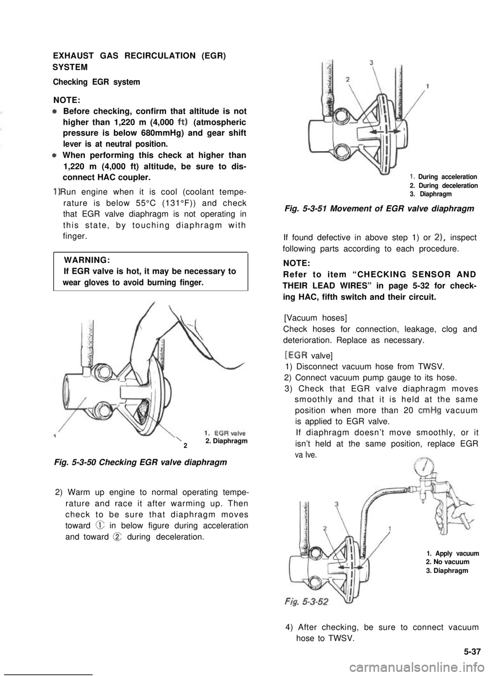
EXHAUST GAS RECIRCULATION (EGR)
SYSTEM
Checking EGR system
NOTE:
1)
Before checking, confirm that altitude is not
higher than 1,220 m (4,000 ft) (atmospheric
pressure is below 680mmHg) and gear shift
lever is at neutral position.
When performing this check at higher than
1,220 m (4,000 ft) altitude, be sure to dis-
connect HAC coupler.
Run engine when it is cool (coolant tempe-
rature is below 55°C (131°F)) and check
that EGR valve diaphragm is not operating in
this state, by touching diaphragm with
finger.
WARNING:
If EGR valve is hot, it may be necessary to
wear gloves to avoid burning finger.
\22. Diaphragm
Fig. 5-3-50 Checking EGR valve diaphragm
2) Warm up engine to normal operating tempe-
rature and race it after warming up. Then
check to be sure that diaphragm moves
toward @ in below figure during acceleration
and toward @ during deceleration.
1. During acceleration
2. During deceleration3. Diaphragm
Fig. 5-3-51 Movement of EGR valve diaphragm
If found defective in above step 1) or 21, inspect
following parts according to each procedure.
NOTE:
Refer to item “CHECKING SENSOR AND
THEIR LEAD WIRES” in page 5-32 for check-
ing HAC, fifth switch and their circuit.
[Vacuum hoses]
Check hoses for connection, leakage, clog and
deterioration. Replace as necessary.
[EGR valve]
1) Disconnect vacuum hose from TWSV.
2) Connect vacuum pump gauge to its hose.
3) Check that EGR valve diaphragm moves
smoothly and that it is held at the same
position when more than 20 cmHg vacuum
is applied to EGR valve.
If diaphragm doesn’t move smoothly, or it
isn’t held at the same position, replace EGR
va Ive.
1. Apply vacuum2. No vacuum
3. Diaphragm
4) After checking, be sure to connect vacuum
hose to TWSV.
5-37