Page 185 of 238
 Using a suitable pair of pliers, disengage the
upper and lower return springs from the leading shoe,
and then remove them from the trailing shoe. (7) Using a pair of pliers, compr")
Brakes 185
(6) Using a suitable pair of pliers, disengage the
upper and lower return springs from the leading shoe,
and then remove them from the trailing shoe. (7) Using a pair of pliers, compress the leading
shoe retainer, turn through ninety degrees and remove
the retainer, spring and pin. Remove the leading shoe
from the backing plate. (8) Using the same procedure, remove the trail-
ing shoe retainer. (9) Lift the trailing shoe from the backing plate
and disconnect the handbrake cable from the hand-
brake lever. Remove the trailing shoe assembly from
the backing plate.
(10) If the brake shoes are to be renewed, remove
the C clip from the trailing shoe and remove the
handbrake lever assembly. (11) If the wheel cylinder is to be overhauled,
proceed as follows:
(a) Disconnect the brake pipe from the rear of
the wheel cylinder and plug the pipe to prevent the
loss of fluid and the ingress of dirt. (b) Remove the bolts retaining the wheel cylin-
der to the backing plate and withdraw the wheel
cylinder from the vehicle. (c) Remove the rubber boots, pistons and spring
from the wheel cylinder bore. Remove the seals from
the pistons. Discard th e rubber boots and seals.
(d) Remove the rubber boot and bleeder valve
from the wheel cylinder.
TO CLEAN AND INSPECT
(1) Thoroughly clean all the brake components,
except the brake shoes in methylated spirits.
(2) Inspect the brake shoe linings. If the thick-
ness of the lining on one or more of the shoes is less
than 1.5 mm thick or contaminated with fluid or
grease, the brake shoes must be renewed as a set. (3) Inspect the wheel cylinder bore and piston
for pitting, wear or damage. Renew the wheel cylinder
assembly if any damage is evident. (4) Check the brake drums for cracks, scoring or
out of round. Renew or machine the brake drums as
necessary.
(5) Inspect the springs and handbrake lever for
fatigue and distortion. Renew as required. (6) Operate the handbrake lever and check for.
smooth operation of the handbrake cable. Renew as
required under the Hand brake Cable and Lever
Assembly heading. (7) Check the bleeder valve for blockage.
(8) Clean and lubricate the adjuster rod.
(9) Clean and inspect the backing plate for
cracks, damage and wear. Renew as required.
TO ASSEMBLE AND INSTAL
(1) If the wheel cylinder was overhauled, pro-
ceed as follows:
(a) Lubricate the pistons and seats with brake
fluid and install the seals on to the pistons so that the
l i p on the seals will be facing towards the centre of the
cylinder.
(b) Install the spring, pistons and rubber boots to
the wheel cylinder ensuring that the rubber boots are
securely located in the cy linder. If necessary, use a
clamp to hold the pistons in the cylinder.
(c) Position the wheel cylinder in the backing
plate and install the brake pi pe to the cylinder. Do not
fully tighten the pipe at this stage. (d) Install the wheel cylinder retaining bolts and
tighten the retaining bolts and brake pipe securely.
Install and tighten the bleeder valve. Install the
valve
boot.
Dismantled view of the right hand rear drum brake
components. Dismantled view of the rear wheel cylinder.
(2) Sparingly lubricate the brake shoe moving
contact surfaces on the backing plate and the adjuster
assembly with a high melting point grease.
(3) If necessary, position the adjusting lever
on
the handbrake lever. (4) If necessary, position the handbrake lever
assembly and washer on the trailing shoe and secure it
with the C clip.
(5) Ensure that the adjuster assembly is adjusted
to its shortest length. (6) Install the adjusting lever return spring to
the
trailing shoe.
Page 186 of 238
 Using a pair of pliers, compress the hand-
brake cable spring and install the cable to the hand-
brake lever.
(8) Position the trailing shoe on the backing
plate with the upper")
186 Brakes
(7) Using a pair of pliers, compress the hand-
brake cable spring and install the cable to the hand-
brake lever.
(8) Position the trailing shoe on the backing
plate with the upper end located on the wheel cylinder
piston and the lower end on the anchor plate. (9) Install the adjuster assembly to the
trailing
shoe ensuring that the adjuster fork is correctly
located on the upper end of the shoe. (10) Install the pin, spring and retainer to the
trailing shoe, turn the reta iner through 90 degrees and
secure the brake shoe to the backing plate. (11) Connect the upper and lower return springs
to the trailing shoe as noted on removal. (12) Position the leading shoe on the backing
plate with the upper end located on the wheel cylinder
piston and the lower end on the anchor plate. Ensure
that the adjuster assembly is correctly located on the
upper end of the shoe. (13) Install the pin, spring and retainer to the
leading shoe, turn the retainer through 90 degrees and
secure the shoe to the backing plate. (14) Connect the upper and lower return springs
to the leading shoe.
(15) By alternatively adjust ing the automatic ad-
juster manually and sliding the brake drum on and off
the brake shoe assembly, adjust the brakes until the
brake drum will just slide over the brake shoes. Ensure
that the adjuster lever contacts the adjuster star wheel.
Install the brake drum and operate the handbrake
several times to adjust the brake shoes. (16) Install the rear wheels and rotate each wheel
to ensure that the brake shoe linings are not dragging.
(17) Bleed the hydraulic system as described
under the Hydraulic System heading. (18) Adjust the handbrake as described under the
Brake Adjustments heading.
8. HANDBRAKE CABLE AND LEVER
ASSEMBLY
HANDBRAKE LEVER AND FRONT CABLE
ASSEMBLY
To Remove and Install
(1) Raise the vehicle and support it on chassis
stands. Release the handbrake.
(2) Working beneath the vehicle, remove the
exhaust pipe centre heat shield retaining bolts and
maneuver the shield from the vehicle. (3) Remove the rear handbrake cable front
clamp retaining nuts and disconnect the rear hand-
brake cable from the equalizer. (4) Working within the vehicle, remove the
carpet square from the rear of the console. Remove
the retaining screw from the front and rear of the rear
console section and maneuver the rear console from
the vehicle.
Dismantled view of the handbrake lever components.
(5) Disconnect the handbrake warning lamp
switch wiring. (6) Remove the handbrake lever assembly re-
taining bolts and remove the handbrake lever and
front cable assembly. (7) If necessary slide the boot and cover towards
the equalizer, straighten the tang on the lower edge of
the lever and remove the adjuster nut and washer.
(8) Withdraw the front cable from the lever and
remove the boot and cover. Inspect the cable for
chafing or broken strands. Renew the cable if damage
is evident. (9) Check the handbrake lever ratchet and pawl
for wear and renew as necessary. Installation is a reversal of the removal procedure
with attention to the following points:
(1) Apply lubricant to all the working parts prior
to installation. (2) Ensure that the handbrake cable clamp is
correctly installed. (3) Adjust the handbrake cable as described
under the Brake Adjustments heading.
REAR HANDBRAKE CABLES
TO Remove and Install
(1) Raise the rear of the vehicle and support it
on chassis stands. Remove th e rear wheels and release
the handbrake.
(2) Working beneath the vehicle, remove the
exhaust pipe centre and rear heat shield retaining
bolts and maneuver the heat shields from the
vehicle.
(3) Remove the bolts and nuts retaining the
handbrake cable clamps to the underbody and discon-
nect the rear handbrake cable from the equalizer.
(4) On disc brake models, remove the handbrake
cable to bracket retaining clip on the rear of the
caliper and disconnect the handbrake cable from the
cam lever. Remove the cable from the vehicle.
(5) On drum brake models , proceed as follows:
(a) Remove and dismantle the rear brakes as
previously described.
Page 187 of 238
 Disengage the handbrake cable return spring
from the backing plate.
<c) Using a hammer and punch, carefully tap the
handbrake cable flange from the rear of the backing
plate and")
Brakes 187
(b) Disengage the handbrake cable return spring
from the backing plate.
handbrake cable flange from the rear of the backing
plate and remove the cable from the vehicle.
(6) Inspect the rear handbrake cables for chafing
or broken strands. Renew the cables if damage is
evident.
Installation is a reversal of the removal procedure
with attention to the following points:
(1) Ensure that the handbrake cable clamps are
correctly installed. (2) On drum brake models, install the
handbrake
cable to the backing plate by carefully tapping the
flange on the handbrake cable. Ensure that the cable is
not damaged. (3) Adjust the handbrake cable as described
under the Brake Adjustments heading.
9. BRAKE ADJUSTMENTS
FRONT AND REAR DISC BRAKES
The disc brakes are self adjusting and no manual
adjustment is required or provided.
REAR DRUM BRAKES
Depress the handbrake lever button, apply and
release the handbrake lever several times to adjust the
rear brake shoes.
HANDBRAKE
(1) Raise the rear of the vehicle and support it
on chassis stands. (2) Remove the carpet square from the rear of
the console. Remove the retaining screws from the
front and rear of the rear console section and manoeu-
vre the rear console from the vehicle. (3) Tighten the adjusting nut until the hand-
brake lever pull is between 7-11 notches. (4) Check that the rear wheels are not binding. If
the rear wheels do not rotate freely refer to the Brakes
Trouble Shooting for possible causes.
(5) With the ignition switched On, check that
the handbrake warning lamp is extinguished when the
lever is fully released. (6) Lower the vehicle to the ground and test the
handbrake on an incline.
10. BRAKE PEDAL
TO REMOVE AND INSTAL
(1) Working inside the vehicle remove the re-
taining clip from the clevis pin and remove the clevis
pin connecting the brake pedal to the pushrod.
Dismantled view of the brake pedal components.
(2) Remove the nut from the pivot bolt and
withdraw the brake pedal pivot bolt.
(3) Maneuver the brake pedal from the mount-
ing bracket. (4) Remove the spring from the brake pedal.
(5) Inspect the return spring for breakage or
fatigue. Renew as required.
(6) Inspect the pedal pivot bolt for damage or
wear. Renew as required. (7) Inspect the brake pedal for wear, cracks or
fatigue. Renew as required. Installation is a reversal of the removal procedure
with attention to the following points:
(1) Sparingly lubricate the pedal pivot bolt and
clevis pin with a suitable grease. (2) Ensure that the brake pedal pivot bolt is
correctly located in the pedal bracket. (3) Ensure that the clevis pin is inserted fully
through the clevis and the retaining clip is correctly
installed. (4) Check and if necessary adjust the brake
pedal height and stop lamp switch as described below.
TO ADJUST PEDAL HEIGHT
The dimension for the pedal height is measured at
right angles from the floor, with the carpet pulled
back, to the centre of the pedal pad.
(1) Working inside the ve hicle, disconnect the
wiring from the stop lamp switch.
(2) Loosen the stop lamp switch locknut and
position the switch away from the brake pedal. (3) Loosen the locknut on the brake pedal push-
rod and adjust the pushrod to achieve a pedal height
of 155-165 mm on manual transaxle models or
164-174 mm on automatic transaxle models. Tighten
the locknut. (4) Adjust the stop lamp switch as described
under the following heading.
Page 188 of 238

188 Brakes
Illustration showing the brake pedal adjustments. Di-
mension H = brake pedal height, Dimension C = stop
lamp switch clearance, Dimension F - brake pedal free
play.
TO ADJUST STOP LAMP SWITCH
(1) Loosen the stop lamp switch locknut and
disconnect the wiring from the switch.
(2) Adjust the stop lamp switch to achieve a
clearance of 0.3-1.0 mm between the pedal stop and
the threaded end of the switch. (3) Tighten the locknut and connect the wiring
to the switch. Ensure that the stop lamps are off when
the pedal is released.
(4) Ensure that the pedal free play is 1.0-3.00
mm after adjustments have been completed.
11. HYDRAULIC SYSTEM
TO BLEED
Bleeding the hydraulic system should only be
necessary when some portion of the hydraulic system
has been disconnected or fluid has been drained,
allowing air to enter the system.
The brake fluid in the hydraulic system should be
changed every 30 000 km or 18 months. The proce-
dure for changing the brake fluid and bleeding the
hydraulic system are simila r with attention to the
notes in the text.
There are four points in the system where bleeder
valves are installed, one on each front caliper and one
on each rear wheel cylinder or rear caliper.
14. Fill the fluid reservoir with clean hydraulic
brake fluid and maintain at least one third full
throughout the entire operation. 15. Attach a transparent hose to the bleeder
valve on the left rear cali per and immerse the other
Bleeding the right hand rear brake caliper.
end of the hose in a small amount of clean brake fluid
contained in a clean glass jar held higher than the
bleeder valve.
14. Unscrew the bleeder valve one
complete turn.
15. Have an assistant depress the brake
pedal slowly to the full extent of its travel. Close
the bleeder valve and allow the brake pedal to
r e t u r n w i t h o u t assistance. 16. Repeat operations (3) and (4) until
a con stant stream of fluid, without any air
bubbles, is being discharged into the gl ass jar,
hold the brake pedal down and tighten the
bleeder valve.
Bleeding the right hand front brake caliper.
Page 189 of 238
Brakes 189
NOTE: If changing the brake fluid, continue to be made. Always use new brake fluid for
bleeding the system until clean new fluid t opping up the reservoir.
flows from the bleeder hose. (6) Carry out the operation on the right front,
Do not allow the fluid level in the reser- right rear, right rear and left front brake in that order.
voir to fall below the one third full level at (7) Replenish the reservoir with the specified
any time during the operation or air will brake fluid to the indicated level and install the
enter the system and a fresh start will have reservoir cap.
Page 190 of 238

190
ELECTRICAL SYSTEM
CAUTION: To prevent severe electrical shock extreme care must be taken when
working on or near the electronic ignition system as dangerous high tension voltages
are produced in both the primary and secondary circuits. See the text fo\
r
precautionary notes.
SPECIFICATIONS
BATTERY
Type ..................................................12 volt lead acid
Polarity to earth .................................... Negative ( - )
Specific gravity:
Fully charged ................................... A bove 1.250
Fully discharged ................................Below 1.130
ALTERNATOR
Make .................................................Bosch or Hitachi
Maximum output .......................................... 70 amps
Polarity to earth .................................... Negative ( - )
Stator windings ......................................... Star wound
Regulator type ................................................ Integral
Brush length minimum:
Bosch ........................................................ 5.0 mm
Hitachi ............................. 6.0 mm or limit mark
STARTER MOTOR
Make .................................................Hitach i or Bosch
Type ............................ 4 pole 4 brush reduction gear
Operation control.................................. Solenoid and
overrunning clutch
Undercut of commutator (maximum):
Hitachi ...................................................... 0.8 mm
Brush length (minimum):
Bosch ........................................................ 8.0 mm
Hitachi ........................................................11 mm
Brush spring tension;
Hitachi ............................................... 15.7-19.6 N
Hitachi:
Drive pinion stopper clearance ........ 0.3-1.5 mm
Selective fit adjuster plates ........ 0.5 and 0.8 mm
IGNITION SYSTEM
The ignition system is an integral part of the
engine management system. The Specifications, testing
and overhaul procedures are fully covered in the Fuel
and Engine Management section.
TORQUE WRENCH SETTINGS
Alternator pulley retaining nut:
Bosch ......................................................... 50 Nm
Hitachi ....................................................... 59 Nm
1. BATTERY AND CHARGING SYSTEM
TROUBLE SHOOTING
BATTERY UNDERCHARGED
3. Loose or broken drive belt: Adjust or renew
the drive belt. 4. Faulty alternator regulator; Renew the regu-
lator unit.
5. Faulty battery: Install a new battery of
the
recommended type and capacity. 6. Faulty alternator: Overhaul or renew the
alternator. 7. Fault in the charging circuit wiring: Check
and repair or renew the wiring harness. 8. Faulty connections in the charging circuit:
Check and repair the connections. 9. Fusible link blown; Rectify the fault and
renew as necessary.
NOTE: Check the state of charge (specific
gravity) of the battery- as described under
the
Battery heading in this section. If the battery
is undercharged, check the possible causes in
the order given.
BATTERY OVERCHARGED
• Faulty alternator regulator unit:
Renew the
regulator unit.
• Faulty alternator: Overhaul or
renew the
alternator. • Faulty charging circuit wiring or
connec-
tions: Check and renew or repair the faulty
compo-
nents.
NOTE: An overcharged battery is indicated
by continual loss of water through boiling.
Page 191 of 238

Electrical System 191
This is usually accompanied by discoloura-
tion of the electrolyte.
CHARGE INDICATOR LAMP REMAINS ON
• Loose or broken alternator drive belt: Adjust
or renew the drive belt.
• Faulty regulator unit: Check and renew the
regulator unit. • Faulty alternator: Check and overhaul the
alternator. • Short to earth in the warning lamp circuit:
Check and repair the circuit.
Checking the alternator drive belt for deterioration.
CHARGE INDICATOR LAMP DOES NOT
OPERATE
• Lamp bulb blown: Check and renew the
faulty bulb. • Open circuit in the wi ring or bulb socket:
Check and rectify the open circuit. • Faulty alternator diode: Overhaul the alter-
nator.
NOISE IN DRIVE BELT OR ALTERNATOR
(1) Drive belt frayed or out of alignment with
the pulleys: Renew the drive bell or align the pulleys.
• Loose alternator moun ting bolts or worn
bearings: Tighten the mounting bolts or renew the
bearings. • Loose alternator pulley: Tighten the pulley
retaining nut.
• Faulty alternator: Overhaul or renew the
alternator. • Faulty diodes in the alternator: Overhaul the
alternator, install a new heat sink.
NOTE: To check if the noise is in the
alternator or drive belt, loosen the alternator
and remove the drive belt. If the noise is
gone when the engine is run for a short time
check the serviceability of the belt and
alternator components.
2. BATTERY AND STARTING SYSTEM TROUBLE SHOOTING
STARTER LACKS POWER TO CRANK ENGINE
(1) Battery undercharged: Check the charging
system and rectify as necessary.
Cleaning the battery terminals using a battery post
cleaner.
• Battery faulty, will not hold charge: Check
and renew the battery. • Battery leads or terminals loose or corroded:
Clean and tighten the leads or terminals.
• Faulty starter motor: Check and overhaul the
starter motor. • Faulty starter solenoid switch or contacts:
Check and renew the solenoid as necessary.
STARTER WILL NOT ATTEMPT TO CRANK
ENGINE
(1 ) Open circuit in the starting system : Check
for dirty or loose leads or terminals, dirty commuta-
tor, faulty solenoid or faulty switch. On automatic
Spin the alternator pulley over by hand to check the
bearings for noise.
Page 192 of 238

192 Electrical System
transaxle models, check for a faulty or incorrectly
adjusted neutral safety switch.
1. Discharged battery: Check for a fault or short
circuit in the system. 2. Battery fully charged but will not crank
engine. Check for a locked drive and ring gear,
internal starter faul t or seized engine.
3. Fusible link blown: Check and repair the
cause and renew as necessary.
NOTE: Rotate the engine by hand to ensure
that the starter drive is not locked with the
flywheel ring gear and t hat the engine is not
seized. Ensure that the ignition key is
turned off before rotating the engine.
3. LIGHTING SYSTEM TROUBLE SHOOTING
LAMP OR LAMPS FAIL TO LIGHT
1. Faulty bulb(s): Check and renew the faulty
bulb(s). 2. Open circuit in the wiring or connections:
Check the lamp circuits and rectify as necessary.
1. Faulty lamp switch: Check and if necessary
renew the lamp switch. 2. Faulty fuse or fuse connection: Repair the
fuse connection or renew the fuse. 3. Lamp relay faulty: Check and renew as
necessary.
NOTE: Switch on the lamps concerned and
using a test lamp, check that the lamp
circuits are operating. This is best done by
starting at the lamp wiring connector or
bulb holder and work ing back to the power
source.
LAMP OR LAMPS INCORRECTLY
ILLUMINATED
1. Lamp or lamps incorrectly earthed: Check
the lamp earth for loosene ss or clean the contact,
either at the lamp body or wire.
2. Incorrect bulbs installe d: Check the bulb
wattage and voltage and renew with the correct type if
necessary. 3. Dirty or damaged lamp reflector: Clean or
renew the lamp reflector. 4. Faulty bulb: Check with a known serviceable
bulb and renew if necessary. 5. Dirty lamp lens: Clean or renew the lamp
lens. 6. High resistance or faulty connections be-
tween the alternator and battery: Check the circuit
and rectify th e condition.
7. Poor earth connection between the battery
and the engine or alternat or: Check the battery earth
lead and the strap between the engine and the body. 8. Voltage regulator faulty: Check and renew
the voltage regulator.
NOTE: The most common cause for this
condition is dirty t erminals on the earth
leads. Check all earth leads at their earthing
points.
4. TURN SIGNAL LAMP TROUBLE SHOOTING
TURN SIGNAL LAMP DOES NOT LIGHT AND
NO AUDIBLE NOISE FROM FLASHER UNIT
(1) Fuse blown: Rectify the fault and renew the
fuse.
(2) The Flasher unit is faulty: Renew the unit
(3) Turn signal switch faulty: Renew the switch
(4) Fault in the wiring circuit: Check and repair
the fault.
TURN SIGNAL WARNING LAMP DOES NOT
FLASH BUT AUDIBLE CLICKING FROM
FLASHER UNIT
(1) Warning lamp bulb blown: Check and renew
the bulb.
Checking the rear combination lamp circuit using a test
lamp.
Checking the headlamp circuit using a test lamp.
 1
1 2
2 3
3 4
4 5
5 6
6 7
7 8
8 9
9 10
10 11
11 12
12 13
13 14
14 15
15 16
16 17
17 18
18 19
19 20
20 21
21 22
22 23
23 24
24 25
25 26
26 27
27 28
28 29
29 30
30 31
31 32
32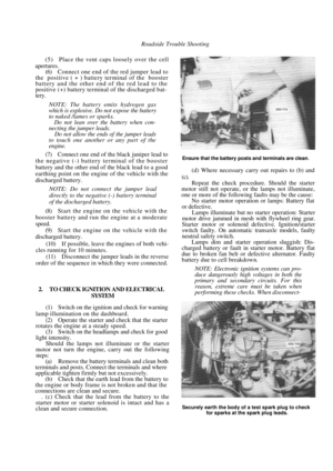 33
33 34
34 35
35 36
36 37
37 38
38 39
39 40
40 41
41 42
42 43
43 44
44 45
45 46
46 47
47 48
48 49
49 50
50 51
51 52
52 53
53 54
54 55
55 56
56 57
57 58
58 59
59 60
60 61
61 62
62 63
63 64
64 65
65 66
66 67
67 68
68 69
69 70
70 71
71 72
72 73
73 74
74 75
75 76
76 77
77 78
78 79
79 80
80 81
81 82
82 83
83 84
84 85
85 86
86 87
87 88
88 89
89 90
90 91
91 92
92 93
93 94
94 95
95 96
96 97
97 98
98 99
99 100
100 101
101 102
102 103
103 104
104 105
105 106
106 107
107 108
108 109
109 110
110 111
111 112
112 113
113 114
114 115
115 116
116 117
117 118
118 119
119 120
120 121
121 122
122 123
123 124
124 125
125 126
126 127
127 128
128 129
129 130
130 131
131 132
132 133
133 134
134 135
135 136
136 137
137 138
138 139
139 140
140 141
141 142
142 143
143 144
144 145
145 146
146 147
147 148
148 149
149 150
150 151
151 152
152 153
153 154
154 155
155 156
156 157
157 158
158 159
159 160
160 161
161 162
162 163
163 164
164 165
165 166
166 167
167 168
168 169
169 170
170 171
171 172
172 173
173 174
174 175
175 176
176 177
177 178
178 179
179 180
180 181
181 182
182 183
183 184
184 185
185 186
186 187
187 188
188 189
189 190
190 191
191 192
192 193
193 194
194 195
195 196
196 197
197 198
198 199
199 200
200 201
201 202
202 203
203 204
204 205
205 206
206 207
207 208
208 209
209 210
210 211
211 212
212 213
213 214
214 215
215 216
216 217
217 218
218 219
219 220
220 221
221 222
222 223
223 224
224 225
225 226
226 227
227 228
228 229
229 230
230 231
231 232
232 233
233 234
234 235
235 236
236 237
237