Page 129 of 238

Manual Transaxle and Drive Shafts 129
renewed as individual units. The C.V. joints are
lubricated in manufacture and need no attention in
service unless one of the r ubber boots is damaged. In
this case the joint can be cl eaned and repacked with
the recommended grease and a new boot installed.
From July 1989, Pulsar Q and Vector SSS manual
transaxle models are equipped with a limited slip
differential incorporating a viscous coupling. The
coupling is not repairable and must be renewed as an
assembly if unserviceable. A test procedure for the
viscous coupling is included in the text in this section.
3. TRANSAXLE ASSEMBLY
Special Equipment Required:
To Dismantle and Assemble — Puller set, press
and press plates, dial gauge
To Measure Mainshaft Turning Torque —
Suitable slotted adaptor and torque gauge
TO REMOVE AND INSTAL
(1) Raise the front of the vehicle and support it
on chassis stands.
(2) Remove the battery as described in the
Electrical System section. (3) Remove the drive shafts as described later in
this section. (4) Disconnect and remove the starter motor as
described in the Elect rical System section.
Front view of the transaxle removed from the vehicle.
(5) Support the rear of the engine using a jack
with a piece of timber between the jack head and the
engine sump.
(6) Remove the bolts retaining the clutch hous-
ing to the engine. (7) Disconnect the vehicle speed sensor wiring,
the reverse lamp wiring, the gear lever control rod and
the gear lever support rod from the transaxle. (8) Remove the transaxle mounting through bolt
and remove the bolts retaining the mounting bracket
to the transaxle.
(9) With the left hand front wheel removed,
remove the left hand inner mudguard panel. (10) Maneuver the transaxle away from the
engine. Lower and withdraw the transaxle from under
the vehicle.
NOTE: Do not allow the transaxle to hang
on the clutch driven plate during removal.
Support the transaxle on a trolley jack if
necessary.
Installation is a reversal of the removal procedure
with attention to the following points:
(1) Lubricate the input shaft splines sparingly
with lithium base molybdenum disulphide grease. (2) Support the transaxle during installation. Do
not allow the transaxle to hang on the clutch driven
plate. (3) Tighten all bolts to the specified torque.
(4) Fill the transaxle with the specified quantity
and grade of oil. (5) Road test the vehicle and check for correct
transaxle operation. Also ch eck for transaxle oil leaks
and rectify as necessary.
TO DISMANTLE
(1) Remove the clutch release components from Rear view of the transaxle removed from the vehicle.
Page 130 of 238

130 Manual Transaxle and Drive Shafts
Internal view of the transaxle showing the installed positions of the shift forks and control bracket.
the clutch housing. Refer to the Clutch section for the
correct procedure.
(2) Thoroughly clean the outsi de of the transaxle
assembly using solvent and compressed air. (3) Remove the bolts retaining the transaxle case
to the clutch housing and using a soft faced hammer,
tap the transaxle case to separate the mating surfaces.
(4) Carefully lift the transaxle case from the
clutch housing. Tilt the cas e to provide clearance for
the fifth gear shift fork. (5) Withdraw the spacer from the reverse idler
shaft and withdraw the fork shaft and spring from the
transaxle. (6) Remove the fifth and third/fourth shift forks
taking care not to lose the shift cap. (7) Remove the retaining bolts and remove the
control bracket and the first/second shift fork taking
care not to lose the shift cap. (8) Lift the mainshaft out of the clutch housing.
NOTE: When lifting, do not tilt the main-
shaft as the resin oil channel behind the
front mainshaft bearing could be damaged.
(9) Lift the differential assembly out of the
clutch housing.
NOTE: For information on the overhaul of
Dismantled view of the striking rod components.
the differential assembly refer to the Differ-
ential and Final Drive Assembly heading.
(10) Remove the retaining bolts from the input
shaft front bearing retainer. (11) Position the transaxle assembly on its side
and tap the input shaft out of the clutch housing using
a soft faced hammer. Remove the input shaft, bearing
retainer and reverse idler gear from the clutch hous-
ing.
(12) Remove the shift check ball, plug and spring
from the passage adjacent to the upper control
bracket retaining bolt on the clutch housing.
(13) Position the striking lever so that the retain-
ing pin will not contact the clutch housing and remove
the pin using a suitable punch.
(14) Remove the striking rod, striking lever and
striking interlock from the clutch housing.
(15) Remove the reverse check plug, spring and
balls from the clutch housing noting the installed
position of the small check ball.
(16) Remove the screws retaining the reverse and
fifth gear check assembly and remove the assembly
from the clutch housing.
(17) Remove and discard the input shaft and
striking rod oil seals from the clutch housing noting
the installed direction of the seals.
(18) Renew the rear input shaft bearing as fol-
lows:
(a) Remove the plastic oil channel from the
transaxle case.
(b) Using a suitable punch through the hole
adjacent to the r ear input shaft bearing, tap the small
welch plug out of the transaxle case.
(c) Using a suitable punch through the small
welch plug opening, tap the rear input shaft bearing
out of the transaxle case. (d) Using a suitable mandrel, tap the new rear
input shaft bearing into the transaxle case.
NOTE: It may be necessary to use a hydrau-
lic press if the bearing is a tight fit in the
housing.
(e) Apply sealer to a new welch plug and tap the
plug squarely into the transaxle case until the edge of
the plug is level with the case.
Dismantled view of the shift fork components.
Page 131 of 238
 Renew the rear mainshaft bearing outer race
as follows:
(a) Remove the bolts retaining the rear cover to
the transaxle case. (b) Remove the rear c")
Manual Transaxle and Drive Shafts 131
(19) Renew the rear mainshaft bearing outer race
as follows:
(a) Remove the bolts retaining the rear cover to
the transaxle case. (b) Remove the rear cover. O ring, spacer and
adjusting shim from the transaxle case. Discard the O
ring. (c) Using a suitable punch, tap the bearing outer
race out of the transaxle case. (e) Install the adjusting shim, spacer and a new O
ring to the transaxle case. Install the rear cover and
tighten the retain ing bolts securely.
(20) Renew the front mainshaft bearing outer
race as follows:
(a) Using a suitable puller, pull the outer race
out of the clutch housing.
(b) Ensure that the oil groove in the resin oil
channel is facing the oil pocket in the clutch housing. (c) Install the new outer race to the clutch
housing.
(21) Measure the end float of the input shaft fifth
gear using feeler gauges betw een the fifth gear and the
adjacent gear shoulder. Note the measurement for
later reference.
(22) Dismantle the input shaft as follows:
(a) Remove the snap ring and spacer from the
front of the input shaft. (b) Using a suitable puller, remove the bearing
from the front of the input shaft. Remove the bearing
retainer noting the installed direction. (c) Remove the snap ring from the rear of the
input shaft. (d) Remove the shift retainer, fifth gear synchro
assembly, fifth gear and th e split bearing from the rear
of the input shaft.
(23) Measure the end float of the mainshaft first,
second, third and fourth gears using feeler gauges
between the gear and the adjacent shaft shoulder.
Note the measurements for later reference.
(24) Dismantle the mainshaft as follows:
(a) Remove the front and rear bearing cones
using a suitable puller.
Dismantled view of the mainshaft.
(b) Remove the C ring holder, the C rings and
the thrust washer from the rear of the mainshaft. (c) Using a puller positioned on the fifth gear
rear flange, remove the fifth gear from the mainshaft. (d) Remove the fourth gear , bush and steel ball
from the mainshaft. (e) Remove the third/fourth synchro assembly,
using a suitable puller if necessary. (f) Remove the third gear, bush, steel ball and
second gear from the mainshaft. (g) Remove the first/second synchro assembly,
using a suitable puller if necessary. (h) Remove first gear and the needle roller
bearing from the mainshaft.
(25) Suitably mark the assembled positions of the
synchro assemblies components and remove the
springs from the assemblies.
(26) Slide the sleeves off the hubs and remove the
shift plates.
(27) Arrange the various synchro components
separately to avoid mixing the components on
assembly.
TO CLEAN AND INSPECT
(1) Clean all the components in cleaning solvent
and allow to dry.
(2) Inspect the teeth on all the gears for wear,
pitting and damage. (3) Push each synchro ring onto its respective
gear cone and measure the distance between the
synchro ring and the synchro teeth on the gear. Renew
the synchro ring and/or the gear if the distance is less
than 0.7 mm.
(4) Inspect the shift forks for excessive clearance
in the synchro sleeves and the control fingers. Renew
the forks as necessary if the clearance is excessive. (5) Inspect the components of the control
bracket for wear and damage. Inspect the shift caps
for wear. Renew the control bracket and/or the shift
caps as necessary.
218/680 INPUTSHAFT M AI N B E AF I N G SPACER
Dismantled view of the input shaft.
Page 132 of 238
 Inspect the striking rod, lever and interlock
for wear and damage paying particular attention to
the detent grooves")
132 Manual Transaxle and Drive Shafts
Check the mainshaft for pitting.
(6) Inspect the striking rod, lever and interlock
for wear and damage paying particular attention to
the detent grooves in the end of the striking rod.
Renew parts as necessary. (7) Inspect the shift check and reverse check
balls and springs for wear, cracks and loss of tension
in the springs. Renew parts as necessary.
Check clearance A between the synchro ring and the
gear synchro teeth and compare with Specifications.
(8) Inspect the reverse and fifth gear check
assembly for wear, damage and loss of spring tension.
Renew the assembly as necessary. (9) Inspect all the bearings for pitting, wear and
damage. Renew the bearings as necessary.
NOTE: If the transaxle has seen consider-
able service, it is advisable to renew all the
bearings, oil seals, O rings and snap rings
during the overhaul.
(10) Inspect the various synchro components for
wear and damage paying par ticular attention to the
shift plates and springs and the internal teeth of the
synchro sleeves. Renew parts as necessary. (11) Compare the various gear end floats mea- sured during dismantling with the Specifications and
if the end floats are excessive, check the contact
surfaces of the ge
ars, shaft and synchro hubs. Renew
worn parts as necessary.
TO ASSEMBLE
(1) Lubricate all the components with the spec-
ified gear oil prior to assembly. (2) Install new input shaft and striking rod
oil
seals to the clutch housing in the direction noted on
removal. Lubricate the oil seal lips with multipurpose
grease prior to installation. (3) Assemble the components of the fifth gear
synchro assembly aligning the marks made on dis-
mantling. Ensure that the ends of the shift plate
springs are not aligned.
(4) Install the split bearing to the rear of the
input shaft and install the fifth gear.
(5) Install the fifth gear sy nchro assembly and the
shift retainer to the rear of the input shaft. Ensure that
the slots in the synchro ring are aligned with the shift
plates.
Check the friction surfaces of the input shaft for pitting. Dismantled view of the fifth gear synchro assembly.
Illustration showing the correct positioning of the shift plates and springs.
Page 133 of 238
 Select a snap ring to obtain the minimum
clearance in the input shaft groove and")
Manual Transaxle and Drive Shafts 133
Dismantled view of the 1st/2nd gear synchro assembly.
(6) Select a snap ring to obtain the minimum
clearance in the input shaft groove and install the snap
ring to the rear of the input shaft.
NOTE: The maximum allowable clearance
is O.I mm. Snap rings are available from
2.00 mm to 2.30 mm in increments of
.05 mm.
(7) Ensure that the fifth gear end float is within
the specifications. (8) Install the bearing retain er to the front of the
input shaft in the direction noted on removal.
(9) Install the front bearing and spacer to
the input shaft. (10) Select a snap ring to obtain the minimum
clearance in the input shaft groove and install the snap
ring to the front of the input shaft.
NOTE: The maximum allowable clearance
is 0.1 mm. Snap rings are available from
1.27 mm to 1.45 mm in increments of
.06 mm.
(11) Assemble the components of the first/
second and third/fourth sy nchro assemblies aligning
the marks made on dismantling. Ensure that the ends
of the shift plate springs are not aligned.
(12) Install the needle roller bearing and first gear
to the mainshaft.
(13) Install the firs t/second synchro assembly to
the mainshaft. Ensure that the slots in the synchro ring are aligned with the shift plates.
(14) Install the steel ball to the mainshaft
using
grease to retain the ball. (15) Install second gear to the mainshaft and
install
the bush aligning the groove in the bush with the steel
ball. (16) Install third gear to the mainshaft.
(17) Install the third/fourth synchro assembly to
the mainshaft ensuring that the slots in the synchro
ring are aligned with the shift plates.
(18) Install the other steel ball to the mainshaft
using grease to retain the ball. (19) Install the fourth gear bush to the mainshaft
aligning the groove in the bush with the ball. (20) Install the fourth gear to the mainshaft.
(21) Install the fifth gear to the mainshaft.
(22) Install the thrust washer to the mainshaft.
(23) Select C rings to obtain the minimum clear-
ance in the mainshaft grooves and install the C rings to
the mainshaft groove. Install the C ring holder to the
mainshaft.
NOTE: The maximum allowable clearance
is 0.1 mm. C rings are available in thick-
nesses of 3.63 mm to 4.54 mm in incre-
ments of 0.07 mm.
(24) Install the rear and front bearing cones to the
mainshaft using a press and press plates. (25) Ensure that the mainshaft first, second, third
and fourth gear end floats are within the Specifica-
tions.
(26) Temporarily install the differential assembly
to the clutch housing. (27) Install the transaxle case to the clutch
hous-
ing. (28) Tighten the transaxle case retaining bolts to
the specified torque. (29) Install a suitable slotted adaptor into
the
differential pinion shaft a nd, using a torque gauge,
measure the differential tu rning torque. The turning
torque should be in a range from slightly below
3.9 Nm to 7.9 Nm. If the turning torque is not as specified, proceed to
the Differential and Final Drive heading and perform
operations (22) to (29).
If the turning torque is as specified, proceed as
follows:
(30) Remove the transaxle case and install
the
mainshaft to the clutch housing ensuring that the resin
oil channel is located centrally in the end of the
mainshaft. (31) Install the transaxle case to the clutch hous-
ing.
Dismantled view of the 3rd/4th gear synchro
assembly.
Page 134 of 238
 Install and tighten the retaining bolts to
the specified torque.
(33) Repeat operation (29). The total turning
torque should be 5.9-13.7 Nm if")
134 Manual Transaxle and Drive Shafts
(32) Install and tighten the retaining bolts to
the specified torque.
(33) Repeat operation (29). The total turning
torque should be 5.9-13.7 Nm if new bearings have
been installed or slightly l ess if the original bearings
have been installed. If the turning torque is no t as specified, adjust the
mainshaft turning torque as follows:
(a) Remove the transaxle case rear cover, O ring,
spacer and adjusting shim from the transaxle case.
(b) Ensure that the mainsh aft rear bearing outer
race is fully seated on the bearing cone. (c) Using micrometer depth gauge, measure the
distance from the transaxle case to the bearing outer
race and note the reading. (d) Referring to the following table, select the
appropriate shim, according to the reading noted in
operation (c), required to correct the mainshaft turn-
ing torque.
READING SHIM
2.35-2.40 mm............................................... 0.10 mm
2.40-2.45 mm............................................... 0.15 mm
2.45-2.50 mm...............................................0.20 mm
2.50-2.55 mm...............................................0.25 mm
2.55-2.60 mm...............................................0.30 mm
2.60-2.65 mm............................................... 0.35 mm
2.65-2.70 mm............................................... 0.40 mm
2.70-2.75 mm............................................... 0.45 mm
2.75-2.80 mm............................................... 0.50 mm
2.80-2.85 mm............................................... 0.55 mm
2.85-2.90 mm............................................... 0.60 mm
2.90-2.95 mm............................................... 0.65 mm
2.95-3.00 mm............................................... 0.70 mm
3.00-3.05 mm............................................... 0.75 mm
3.05-3.10 mm............................................... 0.80 mm
3.10-3.15 mm............................................... 0.85 mm
3.15-3.20 mm............................................... 0.90 mm
3.20-3.25 mm............................................... 0.95 mm
3.25-3.30 mm...............................................1.00 mm.
(e) Install the spacer, shim, O ring and rear
cover to the transaxle case. Tighten the retaining
bolts securely.
(34) Measure the total turning torque as previ-
ously described. (35) Install the striking interlock and striking lever
to the clutch housing. (36) Install the striking ro d to the clutch housing
sliding the rod through the lever and interlock. Take
care that the end of the rod does not damage the seal. (37) Install a new retaining pin to the striking rod
using a pin punch. (38) Install the reverse and fifth gear check
assembly to the clutch housing. Tighten the retaining
screws securely. (39) Install the balls, spring and reverse check
plug to the clutch housing ensuring that the smaller
diameter ball enters the hole in the body of the
reverse and fifth gear check assembly body. Apply locking com-
pound and tighten the reverse check plug securely.
(40) Using a bar clamped to the end of the
striking rod, check that a force of 4.9-7.4 Nm is
required to overcome the spring loading of the reverse
and fifth gear check assembly. If necessary, renew the
springs to achieve this correct spring loading.
NOTE: Ensure that the reverse check plug is
coated with locking compound when finally
installed.
(41) Install the shift check ball, spring and plug to
the clutch housing. Ensure that the ball is centrally
located in the plug.
(42) If removed, install the oil reservoir to the
clutch housing.
(43) Install the input shaft assembly and the
reverse idler gear to the clutch housing taking care not
to damage the seal.
(44) Apply locking compound to the bearing
retainer bolts and tighten the bolts to the specified
torque.
(45) Install the spacer to the reverse idler shaft.
(46) Install the differential assembly to the clutch
housing.
(47) Install the mainshaft to the clutch housing
ensuring that the resin oil ch annel is located centrally
in the end of the mainshaft. (48) Install the shift cap to the slot in the first/
second shift fork and install the shift fork and control
bracket to the clutch housing. Use grease to hold the
shift cap in the shift fork slot. Ensure that the reverse
idler shift fork is correctly located over the gear.
(49) Apply locking compound to the threads of
the control bracket retaining bolts and tighten the
bolts to the specified torque. (50) Install the shift cap in the slot in the third/
fourth shift fork and install the fork to the transaxle
assembly. Use grease to hold the shift cap in the shift
fork slot. (51) Install the fifth gear shift fork to the transaxle
ensuring that the shift fork slot engages the control
finger.
(52) Install the fork shaft an d spring to the clutch
housing sliding the shaft through the shift forks. Use
grease to hold the spring in the end of the shaft. (53) Apply a continuous bead of sealant to the
mating face of the clutch housing so that the bead is
located inside the row of bolt holes.
NOTE: Sealant is available from Nissan
spare parts using the part number KP
610-00250.
(54) Install the transaxle case to the clutch hous-
ing. Install and tighten the retaining bolts to the
specified torque. (55) Select each gear in turn and check that the
transaxle turns freely in each gear. Ensure that it is not
Page 135 of 238

Manual Transaxle and Drive Shafts 135
possible to move the striking rod from fifth gear to
reverse without first moving sideways in the neutral
gate.
4. DIFFERENTIAL AND FINAL DRIVE ASSEMBLY
Special Equipment Required:
To Measure Differential Turning Torque —
Suitable slotted adaptor and torque gauge
TO CHECK VISCOUS COUPLING
From July 1989, Manual transaxle Pulsar Q and
Vector SSS models are equipped with a limited slip
differential incorporating a viscous coupling.
(1) Raise the front of the vehicle and support it
on chassis stands. (2) Rotate one front wheel and check the rota-
tional direction of the opposite wheel. (3) If both front wheels rotate in the same
direction, the viscous coupling is functioning nor-
mally. (4) If the front wheels rota te in opposite direc-
tions, the viscous coupling is unserviceable and must
be renewed as an assembly.
TO DISMANTLE AND ASSEMBLE
It is necessary to remove and dismantle the
transaxle assembly to gain access to the differential
and final drive assembly.
Refer to the Transaxle Assembly heading for the
removal of the transaxle from the vehicle. Operations
1-9 of the dismantling procedure under the same
heading describe the removal of the differential and
final drive assembly from the transaxle.
(1) If necessary, cut and remove the speedome-
ter drive gear from the differential case. (2) Using a suitable puller, remove the differen-
tial carrier bearing cone and roller assemblies from the
differential case and remove the speedometer drive
gear stopper.
(3) Remove the ring gear retaining bolts and
separate the ring gear from the differential case using
a soft faced hammer.
(4) Using a pin punch, remove the retaining pin
from the differential pinion shaft.
(5) Remove the pinion shaft from the differen-
tial case. (6) Remove the pinion gears and thrust washers
from the differential case. (7) Remove the side gears and spacers from the
differential case.
NOTE: If applicable, the viscous coupling is
integral with the left hand side gear.
(8) Wash all the differential components with
cleaning solvent. (9) Check the gears, spacer s, thrust washers,
pinion shaft and differential case for wear, pitting and
damage. Renew parts as necessary.
(10) Install the side gears and spacers to
the
differential case.
(11) Install the pinion gear s and thrust washers
to
the differential case.
(12) Install the pinion shaft to the differential case
aligning the retaining pin hole. (13) Install the retaining pin to the pinion shaft
until the end of the pin is level with the differential
case. (14) With a dial gauge contacting the end of the
side gear, lift the side gear evenly and measure the
clearance between the side gear and the differential
case. The clearance should be 0.1-0.2 mm.
NOTE: Do not tilt the side gear or the dial
gauge reading will be incorrect.
(15) If necessary, adjust the side gear clearance
using selective fit spacers.
NOTE: Spacers are available from 0.15 mm
to 1.00 mm in increments of 0.05 mm.
(16) Measure and if necessary, adjust the other
side gear clearance. (17) On models equipped with a viscous cou-
pling, adjust the side gear clearance as follows:
(a) Temporarily secure the differential case with
two bolts. (b) Position the differential case so that the right
hand side gear is uppermost. (c) Insert a 0.03 mm feeler gauge between the
View of the differential ass embly removed from the
transaxle.
Page 136 of 238
 Insert another 0.03 mm feeler gauge diag")
136 Manual Transaxle and Drive Shafts
right hand side gear and the adjacent spacer in an area
where there is no oil groove in the differential case.
(d) Insert another 0.03 mm feeler gauge diago-
nally opposite the first feeler gauge to avoid tilting the
side gear.
(e) Insert a splined adaptor into the right hand
side gear and attempt to rotate the gear by hand.
(f) If the gear cannot be rotated, change the
thickness of the left hand side gear spacer, repeating
the test until the gear can be rotated.
NOTE: Spacers are available in thicknesses
from 0.8 mm to 1.5 mm in increments of
0.1 mm.
(g) Remove the 0.03 mm feel er gauges and insert
0.09 mm feeler gauges to the same position. The gear
should lock.
(h) The spacer selection is correct when the right
hand side gear can be rotated with 0.03 mm feeler
gauges inserted but locks when 0.09 mm feeler gauges
are inserted.
(18) Install the ring gear to the differential case
with the chamfered edge of the ring gear inwards. (19) Install and tighten the retaining bolts in
a
diagonal sequence to the specified torque.
(20) Install a new speedometer drive gear to
the
differential case. Install the stopper adjacent to the
drive gear.
(21) Install the differentia] carrier bearing
cones
and roller assemblies to the differential case.
(22) Remove the adjusting shim from behind the
carrier bearing outer race in the transaxle case and
replace the outer race in the transaxle case.
(23) Install the differential assembly to the clutch
housing. (24) Install the transaxle case to the clutch housing
and tighten the retaining bolts to the specified torque.
(25) Mount a dial gauge to the clutch housing so
that the contact point is resting on the differential
case. (26) Insert a bar through the opposite side gear
and, contacting the pinion shaft, raise and lower the
differential case and measure the end float in the
carrier bearings. (27) Using the following table, select a shim to
correspond to the relevant end float.
END FLOAT SHIM THICKNESS
0.30-0.34 mm....................................................0.64 mm
0.34-0.38 mm................................................... 0.68 mm
0.38-0.42 mm................................................... 0.72 mm
0.42-0.46 mm................................................... 0.76 mm
0.46-0.50 mm................................................... 0.80 mm
0.50-0.54 mm................................................... 0.84 mm
0.54-0.58 mm................................................... 0.88 mm
0.58-0.62 mm................................................... 0.92 mm
0.62-0.66 mm................................................... 0.96 mm
0.66-0.70 mm................................................... 1.00 mm
0.70-0.74 mm................................................... 1.04 mm
0.74-0.78 mm ................................................... 1.08 mm
0.78-0.82 mm ................................................... 1.12 mm
0.82-0.86 mm ................................................... 1.16 mm
0.86-0.90 mm ................................................... 1.20 mm
0.90-0.94 mm ................................................... 1.24 mm
0.94-0.98 mm ................................................... 1.28 mm
0.98-1.02 mm ................................................... 1.32 mm
1.02-1.06 mm ................................................... 1.36 mm
1.06-1.10 mm ................................................... 1.40 mm
1.10-1.14 mm ................................................... 1.44 mm
1.14-1.18 mm ................................................... 1.48 mm
1.18-1.22 mm ................................................... 1.52 mm
1.22-1.26 mm ................................................... 1.56 mm
1.26-1.30 mm ................................................... 1.60 mm
1.30-1.34 mm ................................................... 1.64 mm
1.34-1.38 mm ................................................... 1.68 mm
1.38-1.42 mm ................................................... 1.72 mm
1.42-1.46 mm ................................................... 1.76 mm
The thickest shim available is 0.88 mm. Multiple
shims are required above this thickness.
(28) Install the shim behind the carrier
bearing
outer race in the transaxle case and assemble the unit
once more. (29) Using a suitable slotted adaptor engage the
pinion shaft and using a to rque gauge, measure the
differential turning torque. The turning torque when new carrier bearings
have been installed should be 3.9-7.8 Nm or slightly
lower if the original carrier bearings have been
replaced.
(30) Assemble the transaxle and measure the total
turning torque of the diff erential assembly and the
mainshaft. The total turning torque should be 5.9 to
13.7 Nm with new bearings or slightly lower if the
original bearings have been replaced.
5. GEAR LEVER ASSEMBLY
TO DISMANTLE AND ASSEMBLE
(1) Remove the gear lever knob and remove the
centre console as described in the Body section. If not
previously removed, remove the rubber boot sur-
rounding the gear lever. (2) Raise the front of the vehicle and support it
on chassis stands. Remove the catalytic converter and
heat shield as described in the Engine section.
(3) Remove the bolt and disconnect the control
rod from the bottom of the gear lever, noting the
position of the return spring and bracket.
(4) Remove the nuts retaining the gear lever
socket to the support rod. (5) Working inside the vehicle, lift the gear lever
out of the floor bracket. (6) Separate the lower rubber boot, socket,
spring seat, spring, upper ball seat and lower ball seat
from the gear lever, noting the location of each
component to aid assembly.
 1
1 2
2 3
3 4
4 5
5 6
6 7
7 8
8 9
9 10
10 11
11 12
12 13
13 14
14 15
15 16
16 17
17 18
18 19
19 20
20 21
21 22
22 23
23 24
24 25
25 26
26 27
27 28
28 29
29 30
30 31
31 32
32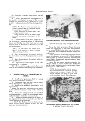 33
33 34
34 35
35 36
36 37
37 38
38 39
39 40
40 41
41 42
42 43
43 44
44 45
45 46
46 47
47 48
48 49
49 50
50 51
51 52
52 53
53 54
54 55
55 56
56 57
57 58
58 59
59 60
60 61
61 62
62 63
63 64
64 65
65 66
66 67
67 68
68 69
69 70
70 71
71 72
72 73
73 74
74 75
75 76
76 77
77 78
78 79
79 80
80 81
81 82
82 83
83 84
84 85
85 86
86 87
87 88
88 89
89 90
90 91
91 92
92 93
93 94
94 95
95 96
96 97
97 98
98 99
99 100
100 101
101 102
102 103
103 104
104 105
105 106
106 107
107 108
108 109
109 110
110 111
111 112
112 113
113 114
114 115
115 116
116 117
117 118
118 119
119 120
120 121
121 122
122 123
123 124
124 125
125 126
126 127
127 128
128 129
129 130
130 131
131 132
132 133
133 134
134 135
135 136
136 137
137 138
138 139
139 140
140 141
141 142
142 143
143 144
144 145
145 146
146 147
147 148
148 149
149 150
150 151
151 152
152 153
153 154
154 155
155 156
156 157
157 158
158 159
159 160
160 161
161 162
162 163
163 164
164 165
165 166
166 167
167 168
168 169
169 170
170 171
171 172
172 173
173 174
174 175
175 176
176 177
177 178
178 179
179 180
180 181
181 182
182 183
183 184
184 185
185 186
186 187
187 188
188 189
189 190
190 191
191 192
192 193
193 194
194 195
195 196
196 197
197 198
198 199
199 200
200 201
201 202
202 203
203 204
204 205
205 206
206 207
207 208
208 209
209 210
210 211
211 212
212 213
213 214
214 215
215 216
216 217
217 218
218 219
219 220
220 221
221 222
222 223
223 224
224 225
225 226
226 227
227 228
228 229
229 230
230 231
231 232
232 233
233 234
234 235
235 236
236 237
237