Page 177 of 238
 Install the second garter spring. Insert
a
machined drift into the bore and lightly push the
garter")
Brakes 177
installed. Install the second back up ring, large
diam-
eter first.
(6) Install the second garter spring. Insert
a
machined drift into the bore and lightly push the
garter spring into its locating groove.
(7) Smear the secondary piston with clean brake
fluid. Ease the seal over the piston body into the
groove adjacent to the spring, ensuring that the seal lip
faces the spring and that the nylon spacer is against
the back of the seal. (8) Install the guide onto the secondary
piston,
large internal diameter first, followed by the main seal
with the lip facing away from the spring. (9) Lubricate the secondary piston assembly
with clean brake fluid and install the secondary spring
and retainer to the piston. Install the complete assem-
bly into the master cylinder bore. (10) Smear the primary piston with clean brake
fluid. Install the guide, large internal diameter first,
followed by the main seal with the lip facing towards
the small end of the piston.
(11) Install the retainer to the spigot on the front
end of the primary piston ensuring that the legs of the
retainer engage with the groove on the piston. (12) Lubricate the primary piston assembly with
clean brake fluid and install the assembly into the
master cylinder bore. With a blunt rod, push the
assembly down the bore sufficiently to preload the
pistons. While holding the preload, install the stop pin
and valve assemblies into
the master cylinder body and tighten securely. (13) Install a new O ring to the groove on the boss
of the mounting flange of the master cylinder.
(14) Install new O rings to th e pressure differential
pistons, smear them with cl ean brake fluid and install
them into the master cylinder body. (15) Install a new O ring to the pressure differen-
tial end plug, install the plug to the master
cylinder
body and tighten to the specified torque. (16) Using a blunt probe entered through the
sensing switch location hole, separate the pressure
differential pistons and install the switch actuating
lever between them. (17) Screw the sensing switch into its locating
hole until the detents on the switch body just contact
the locating hole facing (w ith the radial grooves).
Screw the switch assembly in a further half to one full
turn ensuring that the dete nts locate in the grooves.
(18) Install new valve seal s to the proportioning
valve plungers, with the serrations of the seals facing
away from the hexagons of the plungers.
(19) Install the new O rings to the
proportioning
valve plugs. (20) Install the valve springs over the stems of the
proportioning valves, insert the install the valve
plugs.
Tighten the plugs to the specified torque.
(21) Install a new O ring to the base of the fast fill
valve assembly. Install a new valve washer to the base
of the valve.
(22) Install the fast fill valve assembly in
the
primary reservoir port (nearest to the mounting flange
of the master cylinder) and install the snap ring
to
retain the assembly. Ensure that the snap ring is
correctly seated in the groove. (23) Smear the new reservoir retainers with clean
brake fluid and install them into the reservoir ports.
Carefully press the brake fluid reservoir into position,
ensuring that the outlet extensions are fully inserted in
the reservoir retainers. (24) Install the reservoir cap insert to the dia-
phragm and press the cap assembly onto the reservoir.
TO INSTAL
Installation is a reversal of the removal procedure
with attention to the following points:
(1) Pour a small amount of clean brake fluid into
the reservoir and pump the master cylinder pistons
with a blunt rod until fluid begins to emerge from the
outlets. (2) Install the master cylinder to the brake servo
unit and loosely install the master cylinder retaining
nuts. (3) Connect the brake pipes to the master cylin-
der outlets, but do not tighten at this stage. (4) Securely tighten the nuts retaining the master
cylinder to the brake servo unit.
(5) Securely tighten the brake pipes and connect
the wiring to the pressure sensing switch.
(6) Fill the master cylinder reservoir with clean
brake fluid and bleed the brakes as described under
the Hydraulic System heading. (7) Check and if necessary adjust the brake
pedal height and free play as described under the
Brake Pedal heading.
4. BRAKE SERVO UNIT
TO CHECK OPERATION
(1) With the engine switched off, apply the
footbrake several times to exhaust all vacuum from
the system.
(2) Apply the footbrake and hold the brake pedal
fully depressed.
(3) Start the engine. If the servo unit is function-
ing satisfactorily a distinct downward movement of
the
brake pedal should be noticed. Should the pedal fail to move downward when the
engine has been started, the vacuum system can be
considered inoperative.
NOTE: If the pedal continues to fall away
there is a fault in the hydraulic system.
(4) Ensure that the brake pedal is fully released,
start the engine and run it at medium speed. Stop the
engine.
Page 178 of 238

178 Brakes
Let the vehicle stand for 1-2 minutes, press the
brake pedal two or three times and check its opera-
tion.
If there is no vacuum assistance, the vacuum
system has developed a leak or the one way check
valve is defective.
NOTE: Before removing the servo unit from
the vehicle for inspection, disconnect the
hose from the servo unit, start the engine
and check that the manifold vacuum is in
fact reaching the servo unit. Also test the one
way check valve as described below,
TO TEST ONE WAY CHECK VALVE
(1) Disconnect the hose and remove the check
valve from the servo unit.
(2) Check the valve for sticking. Suction on the
manifold side should allo w air to flow freely. Air
blown into the valve from the manifold side should
not be able to flow through the valve. (3) Install the valve and check the operation
of
the servo unit as previously described.
NOTE: Check that there are no air leaks at
the hose connections and that the hose clips
are tight. Also check that the hose is not
bulged or collapsed due to deterioration.
Checking for vacuum at the servo unit. The engine
must be running for this test.
TO REMOVE
(1) Raise the bonnet and install covers to both
front mudguards.
(2) On 1.6 liter models, remove the air cleaner
assembly from the vehicle. If necessary refer to the
Fuel System section.
(3) On vehicles equipped with power steering,
remove the reservoir from the bulkhead and move it
to one side. If necessary refer to the Steering section.
(4) Disconnect the vacuum supply hose from the
servo unit.
View of the brake servo unit and associated compo-
nents.
(5) Remove the master cylinder as described
under the Master Cylinder heading. (6) Working inside the vehicle, remove the clip
and clevis pin connecting the pushrod to the brake
pedal. (7) Remove the nuts retaining the servo unit to
the bulkhead and maneuver the servo unit and
spacer block from the vehicle.
TO INSTAL
Installation is a reversal of the removal procedure
with attention to the following points:
(1) With the servo unit and master cylinder
installed to the vehicle, bleed the hydraulic system as
described under the Hydr aulic System heading.
(2) Check and if necessary adjust the brake
pedal height and free play as described under the
Brake Pedal heading.
5. FRONT BRAKES
Special Equipment Required:
To Check Disc Runout — Dial gauge
To Check Disc Thickness — Micrometer
TO CHECK AND RENEW BRAKE PADS
(1) Raise the front of the vehicle and place it on
chassis stands. Remove the front wheels.
(2) Inspect the brake pads on both sides of the
vehicle. If the friction material on one or more of the
pads is less than 2 mm thick or contaminated with
fluid or grease, renew the brake pads as a set as
follows.
NOTE: If the brake pads are contaminated,
trace and rectify the cause prior to installing
the new set of pads.
(3) Drain approximately two thirds of the brake
fluid from the master cylinde r reservoir. This can be
done by loosening the bleeder valve on the caliper and
allowing the fluid to drai n into a container. Discard
this fluid.
Page 179 of 238

Brakes 179
Installed view of the front brake pads, spring clips and shims.
NOTE: Do not drain all the fluid from the
reservoir or it will be necessary to bleed the
hydraulic system. The fluid is drained from
the reservoir to prevent overflow when the
caliper piston is pushed back into the caliper
bore to facilitate pad renewal.
(4) Remove the lower guide bolt and rotate the
caliper body upwards, pivoting on the upper guide
bolt.
(5) Remove the brake pad assemblies from the
anchor plate. (6) Noting the installed positions, remove the
spring clips from the anchor plate and the shims from
the brake pads.
(7) Squarely push the piston into its bore in the
caliper body. If necessary, us e a G clamp to push the
piston into the caliper b ody. Check for fluid leaks
from the calip er body.
(8) If necessary, check the disc runout and
thickness as described under the Brake Disc heading.
(9) Ensure that the guide bolts move freely in the
anchor plate and that the dust boots are in good
condition. (10) Install the brake pads, shims and spring
clips
in the position noted on removal. (11) Rotate the caliper body downwards, to re-
turn to its original position. Lubricate the lower guide
bolt with suitable grease. In stall and tighten the guide
bolt to the specified torque. (12) Repeat the procedure on the opposite front
brake assembly. (13) Replenish the master cylinder reservoir with the recommended fluid to the correct level and pump
the brake pedal several times to locate the disc pads.
(14)
Install the front wheels and lower the
vehicle
to the ground. (15) Road lest the vehicle and check for correct
brake operation.
CALIPER
To Remove and Install
(1) Raise the front of the vehicle and place it on
chassis stands. Remove the relevant front wheel. (2) Remove the brake hose retaining bolt and
plug the hose to prevent the loss of fluid and the
ingress of dirt. (3) Remove the bolts retaining the caliper an-
chor plate to the steering knuckle and slide the caliper
off the disc.
Installed view of the front brake caliper.
Installation is a reversal of the removal procedure
with attention to the following points:
(1) Tighten the caliper anch or plate bolts to the
specified torque.
(2) Install the brake hose to the caliper
body
ensuring that new seal washers are installed.
NOTE: Ensure that the brake hose is cor-
rectly located against the protrusion on the
caliper body.
(3) Bleed the brake hydraulic system as de-
scribed under the Hydraulic System heading. (4) Install the fron t wheel and lower the vehicle
to the ground. (5) Road test the vehicle and check for correct
brake operation.
To Dismantle
(1) Raise the front of the vehicle and place it on
chassis stands. Remove the relevant front wheel.
(2) Remove the brake hose retaining bolt from
Page 180 of 238
 Remove the guide bolts and slide the caliper")
180 Brakes
the caliper body. Plug the brake hose to prevent the
loss of fluid and the ingress of dirt. Remove and
discard the sealing washers.
(3) Remove the guide bolts and slide the caliper
body from the anchor plate and pad assembly. (4) Remove the piston dust cover retaining clip.
Remove and discard the dust cover.
BRAKEPAD BRAKE PAD
Dismantled view of the front brake caliper.
(5) Place a piece of wood in front of the piston
and using low air pressure applied to the brake hose
aperture, gently force the piston from the caliper bore.
(6) Using a thin blunt probe, preferably made
from wood or plastic, remove and discard the piston
seal from the groove in the caliper bore. (7) Clean all the caliper components in methyl-
ated spirits and arrange the components in order, on
a clean, dry surface to aid in assembly.
To Inspect
(1) Inspect the caliper bore and piston for pit-
ting, wear or damage. Renew the caliper assembly or
piston if damage is evident.
NOTE: Slight rust spots in the caliper bore
may he removed with fine emery paper. The
piston must not be polished as the plated
surface wilt be damaged.
(2) Inspect the guide bolts for wear or damage.
Renew as necessary.
To Assemble
(1) Dip a new piston seal in clean hydraulic
brake fluid. Insert the seal into the groove in the
caliper bore ensuring that the seal is correctly seated
and not twisted.
(2) Install a new dust cover to the piston prior to
installing the piston to the caliper bore. (3) Coat the piston and caliper bore with clean
hydraulic brake fluid and insert the piston squarely
into the caliper bore.
(4) Locate the dust seal in the groove of the
caliper body and install the retaining clip.
(5) Lubricate the guide bolts using a suitable
grease. Install the caliper body to the anchor plate and
install and tighten the guide bolts to the
specified
torque. (6) Replenish the master cylinder reservoir with
the recommended fluid and bleed the brakes as
described under the Hydr aulic System heading.
(7) Install the front wheels and lower the vehicle
to the ground. (8) Road test the vehicle and check for correct
brake operation.
BRAKE DISC
To Check Runout
(1) Raise the front of the vehicle and support it
on chassis stands. Remove the relevant front wheel. (2) Install the wheel nuts with the flat side of
the
wheel nut towards the disc. Lightly tighten the nuts to
secure the disc against the hub.
Rotate the hub and check for disc runout.
(3) Mount a dial gauge stand to a suspension
component and position the dial gauge plunger
against the wheel hub. Check that the end float is less
than 0.05 mm. Excessive e nd float will necessitate
renewal of the hub bearing. (4) Position the dial gauge plunger against the
centre of the brake disc. Ro tate the hub and measure
the runout. Maximum allowable runout is 0.07 mm. (5) If the runout exceeds Specifications, machine
or renew the brake disc. (6) Install the fron t wheel and lower the vehicle
to the ground.
To Remove and Install
(1) Raise the front of the vehicle and support it
on chassis stands. Remove the relevant wheel. (2) Remove the bolts retaining the caliper an-
Page 181 of 238
 Suitably mark the location of the di")
Brakes 181
chor plate to the steering knuckle and slide the caliper
off the brake disc. Suspend the caliper clear of the
work area using wire or cord.
(3) Suitably mark the location of the disc in
relation to the hub.
(4) Slide the disc off the hub. If the disc is
difficult to remove, install two M8 x 1.25 mm bolts in
the disc and by alternatively tightening the bolts,
remove the disc.
Do not use a hammer to remove the disc.
Installation is a reversal of the removal procedure
ensuring that the mating face s of the disc and hub are
clean and free from burrs and that the marks made on
removal are aligned.
To Inspect
(1) Inspect the machined faces of the disc for
scores, cracks, wear and signs of overheating. (2) Using a micrometer, measure the thickness
of the disc at several positi ons around the face of the
disc. Renew the disc if the minimum thickness is
below Specifications.
Inspect the brake discs for scoring and wear.
(3) If the disc thickness is satisfactory but the
disc is scored, machine equal amounts from the
machined face on each side of the disc, to restore the
serviceability of the disc.
NOTE: Disc machining is best entrusted to
a reliable brake specialist who can advise on
disc serviceability.
6. REAR DISC BRAKES
Special Equipment Required:
To Check Disc Runout — Dial gauge
To Check Disc Thickness — Micrometer
TO CHECK AND RENEW BRAKE PADS
( 1 ) Raise the rear of the vehicle and place it on
chassis stands. Remove the rear wheels.
Renew the rear brake pads if the friction material is less
than 2 mm thick.
(2) Inspect the brake pads on both sides of the
vehicle. If the friction material on one or more of the
pads is less than 2 mm thick or contaminated with
fluid or grease, renew the brake pad as a set as follows.
NOTE: If the brake pads are contaminated
trace and rectify the cause prior to installing
the new set of pads.
(3) Drain approximately two thirds of the brake
fluid from the master cylinder reservoir. This can be
done by loosening the bleeder valve on the caliper and
allowing the fluid to drai n into a container. Discard
this fluid.
NOTE: Do not drain all the fluid from the
reservoir otherwise it will be necessary to
bleed the hydraulic system. The fluid is
drained from the reservoir to prevent over-
flow when the caliper piston is pushed back
into the caliper bore to facilitate pad re-
newal.
(4) Remove the guide bolts and lift the caliper
body clear of the disc.
NOTE: Do not allow the caliper to hang on
the brake hose.
(5) Noting the installed positions, remove the
brake pads, shims and spring clips from the anchor
plate.
(6) Using a pair of long nosed pliers with the
nose located in the recesses of the piston, rotate the
piston clockwise to retract it into the cylinder body.
Align the recesses between the brake pad retaining
lugs on the caliper body. Refer to the illustration. (7) If necessary, check the disc runout and
thickness as described under the Brake Disc heading.
(8) Ensure that the guide bolts move freely in the
caliper body and that the dust boots are in good
condition.
Page 182 of 238
 Install the brake pads, shims and spring
clips
in the position noted on removal. (10) Install th")
182 Brakes
Illustration of the rear disc caliper showing the correct
piston alignment.
(9) Install the brake pads, shims and spring
clips
in the position noted on removal. (10) Install the caliper body to its original posi-
tion. Lubricate the guide bolts with suitable grease.
Install and tighten the guide bolts to the specified
torque. (11) Repeat the procedure on the opposite rear
brake assembly.
(12) Replenish the master cylinder reservoir with
the recommended fluid to the correct level and pump
the brake pedal several times to locate the disc pads. (13) Install the rear wheels and lower the vehicle
to the ground. (14) Road test the vehicle and check for correct
brake operation.
CALIPER
To Remove and Install
(1) Raise the rear of the vehicle and place it on
chassis stands. Remove the relevant rear wheel. (2) Remove the brake hose retaining bolt from
the caliper body and plug the hose to prevent the
loss of fluid and the ingress of dirt.
Installed view of the rear brake caliper.
(3) Remove the handbrake cable bracket retain-
ing bolts and disconnect the handbrake cable from the
cam lever. (4) Remove the bolts retaining the caliper an-
chor plate. Remove the caliper from the disc. Installation is a reversal of the removal procedure
with attention to the following points:
(1) Tighten the caliper anch or plate bolts to the
specified torque. (2) Install the brake hose to the caliper body
ensuring that new seal washers are installed.
NOTE: Ensure that the brake hose locating
pin is correctly installed in the caliper body.
de-
(3) Bleed the brake hydraulic system as
scribed under the Hydraulic System heading. (4) Install the rear wheel and lower the vehicle to
the ground. (5) Road test the vehicle and check for correct
brake operation.
Dismantled view of the rear brake caliper
Page 183 of 238
 Raise the rear of the vehicle and place it on
chassis stands. Remove the relevant rear wheel.
(2) Remove the brake hose retaining bolt from
the caliper body and plu")
Brakes 183
To Dismantle
(1) Raise the rear of the vehicle and place it on
chassis stands. Remove the relevant rear wheel.
(2) Remove the brake hose retaining bolt from
the caliper body and plug the hose to prevent the loss
of fluid and the ingress of dirt. (3) Remove the handbrake cable bracket retain-
ing bolt and disconnect the handbrake cable from the
cam lever.
(4) Remove the guide bolts and slide the caliper
body off the pads. (5) Using a pair of long nose pliers with the nose
located in the recesses of the piston, rotate the piston
anticlockwise to remove it from the caliper body.
(6) Remove the dust cover retaining clip and dust
cover. Discard the dust cover. (7) Using a thin blunt probe, preferably made
from wood or plastic, remove and discard the piston
seal from the groove in the caliper bore. (8) Using internal snap ring pliers, remove the
snap ring from the caliper bore. (9) Withdraw the spring cover, spring, key plate,
pushrod and link from the caliper bore. Do not mix
these components from the left and right hand sides as
they differ. (10) Remove and discard the O ring from the
pushrod. (11) Remove the spring, nut and washer from the
cam lever. Remove the cam lever and cam from the
caliper body. (12) Remove the cam seal from the caliper using a
screwdriver.
(13) Clean all the caliper components in methy-
lated spirits and arrange the components in order on a
clean dry surface to aid assembly.
To Inspect
(1) Inspect the caliper bore and piston for pit-
ting, wear or damage. Renew the caliper assembly or
piston if damage is evident.
NOTE: Slight rust spots in the caliper bore
may be removed with fine emery paper. The
piston must not be polished as the plated
surface will be damaged.
(2) Inspect the guide bolts for wear or damage
and renew as necessary.
(3) Inspect the threads of the pushrod for wear or
damage and renew as necessary. (4) Inspect the nut inside the piston for wear,
damage and security. Renew the piston if any damage
is evident. (5) Inspect the cam for wear, damage or pitting,
renew as necessary. (6) Inspect the cam bearing in the caliper body
for wear, damage or pitting and renew the seal and
bearing as necessary. (7) Inspect the guide bolt rubbers for deteriora-
tion, wear or damage. Renew as required. To Assemble
(1)
Lubricate the cam bearing with multipurpose
grease and install the seal. (2) Install the cam and cam lever to the
caliper
body. Install the cam lever spring, washer and nut, and
tighten the nut to the specified torque. (3) Install a new O ring to the pushrod and
install
the link, pushrod, key plate, spring and spring cover to
the caliper body. The key plate must engage the caliper
body. Secure the assembly with the snap ring. (4) Dip a new piston seal in clean hydraulic brake
fluid. Insert the seal into the groove in the caliper bore
ensuring that the seal is correctly seated and not
twisted. (5) Install a new dust cover to the piston prior
to
installing the piston to the caliper bore.
(6) Coat the piston and caliper bore with clean
hydraulic brake fluid and using long nose pliers rotate
the piston clockwise into the caliper bore. (7) Locate the dust seal in the groove of the
caliper body and install the retaining clip.
(8) Lubricate the guide bolts using a suitable
grease. Install the caliper body and tighten the guide
bolts to the specified torque. (9) Replenish the master cylinder reservoir with
the recommended fluid and bleed the brakes as
described under the Hydraulic System heading. (10) Install the rear wheel and lower the vehicle to
the ground. (11) Road test the vehicle and check for correct
brake operation.
BRAKE DISC
To Check Runout
(1) Raise the rear of the vehicle and support it on
chassis stands. Remove the relevant rear wheel.
(2) Mount a dial gauge stand to a suspension
component and position the dial gauge plunger
against the wheel hub. Check that the end float is less
Using a dial gauge to measure the rear disc runout.
Page 184 of 238
 Position the dial gauge plunger agains")
184 Brakes
than 0.05 mm. If the wheel hub end float exceeds
Specifications, the bearing must be renewed as de-
scribed in the Rear Suspension section.
(3) Position the dial gauge plunger against the
centre of the brake disc contact area. Rotate the hub
and measure the runout. Ma ximum allowable runout
is 0.07 mm. (4) If the runout exceeds the specified amount,
machine or renew the brake disc. (5) Install the rear wheel and lower the vehicle to
the ground. (6) Road test the vehicle and check for correct
brake operation.
To Remove and Install
(1) Raise the rear of the vehicle and support it
on chassis stands. Remove the relevant rear wheel.
(2) Remove the clip securing the brake hose to
the suspension unit and disengage the hose. (3) Remove the bolts retaining the caliper an-
chor plate. (4) Slide the caliper from the brake disc and
suspend the caliper clear of the work area using wire
or cord.
NOTE: Do not allow the caliper to hang on
the brake hose.
(5) Remove the grease cap from the rear hub.
(6) Remove the split pin, nut retainer, hub nut
and washer from the stub axle. (7) Remove the hub assembly from the stud
axle. Installation is a reversal of the removal procedure
with attention to the following points:
(1) Tighten the rear hub to the specified torque.
(2) Install the brake caliper and tighten all the
bolts to the specified torque. (3) Rotate the hub and check for roughness. If
the hub does not rotate smoothly, renew the hub
bearing as described in the Rear Suspension section. (4) Install the rear wheel and lower the vehicle to
the ground.
(5) Road test the vehicle and check for correct
brake operation.
To Inspect
(1) Inspect the machined faces of the disc for
scores, cracks, wear and signs of overheating. (2) Using a micrometer, measure the thickness
of the disc at several posit ions around the face of the
disc. Renew the disc if the minimum thickness is
below Specifications.
(3) If the disc thickness is satisfactory but the
disc is scored, machine equal amounts from the
machined face on each side of the disc, to restore the
serviceability of the disc.
Inspect the machined faces of the disc for scores,
cracks, wear and signs of overheating.
NOTE: Disc machining is best entrusted to
a reliable brake specialist who can advise on
disc serviceability.
7. REAR DRUM BRAKES
TO REMOVE AND DISMANTLE
(1) Raise the rear of the vehicle and support it
on chassis stands. Remove th e rear wheels and release
the handbrake.
(2) Remove the grease cap from the rear hub.
(3) Remove the split pin, nut retainer, hub nut
and washer from the stub axle. Remove the brake
drum and hub assembly.
(4) Mark each brake shoe and spring to ensure
correct assembly. (5) Rotate the star wheel until the adjuster
assembly is at its shortest length.
Installed view of the left hand side rear drum brake
components.
 1
1 2
2 3
3 4
4 5
5 6
6 7
7 8
8 9
9 10
10 11
11 12
12 13
13 14
14 15
15 16
16 17
17 18
18 19
19 20
20 21
21 22
22 23
23 24
24 25
25 26
26 27
27 28
28 29
29 30
30 31
31 32
32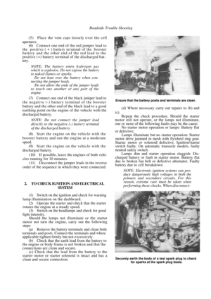 33
33 34
34 35
35 36
36 37
37 38
38 39
39 40
40 41
41 42
42 43
43 44
44 45
45 46
46 47
47 48
48 49
49 50
50 51
51 52
52 53
53 54
54 55
55 56
56 57
57 58
58 59
59 60
60 61
61 62
62 63
63 64
64 65
65 66
66 67
67 68
68 69
69 70
70 71
71 72
72 73
73 74
74 75
75 76
76 77
77 78
78 79
79 80
80 81
81 82
82 83
83 84
84 85
85 86
86 87
87 88
88 89
89 90
90 91
91 92
92 93
93 94
94 95
95 96
96 97
97 98
98 99
99 100
100 101
101 102
102 103
103 104
104 105
105 106
106 107
107 108
108 109
109 110
110 111
111 112
112 113
113 114
114 115
115 116
116 117
117 118
118 119
119 120
120 121
121 122
122 123
123 124
124 125
125 126
126 127
127 128
128 129
129 130
130 131
131 132
132 133
133 134
134 135
135 136
136 137
137 138
138 139
139 140
140 141
141 142
142 143
143 144
144 145
145 146
146 147
147 148
148 149
149 150
150 151
151 152
152 153
153 154
154 155
155 156
156 157
157 158
158 159
159 160
160 161
161 162
162 163
163 164
164 165
165 166
166 167
167 168
168 169
169 170
170 171
171 172
172 173
173 174
174 175
175 176
176 177
177 178
178 179
179 180
180 181
181 182
182 183
183 184
184 185
185 186
186 187
187 188
188 189
189 190
190 191
191 192
192 193
193 194
194 195
195 196
196 197
197 198
198 199
199 200
200 201
201 202
202 203
203 204
204 205
205 206
206 207
207 208
208 209
209 210
210 211
211 212
212 213
213 214
214 215
215 216
216 217
217 218
218 219
219 220
220 221
221 222
222 223
223 224
224 225
225 226
226 227
227 228
228 229
229 230
230 231
231 232
232 233
233 234
234 235
235 236
236 237
237