1987 MITSUBISHI MONTERO relay
[x] Cancel search: relayPage 1 of 284

Service Manual
MONTERO
1987 : Volume 2
FOREWORD
This Service Manual has been prepared with the
latest service information available at the time of
publication. It is subdivided into various group
categories and each section contains diagnosis,
disassembly, repair, and installation procedures
along with complete specifications and tightening
references. Use of this manual will aid in properly
performing any servicing necessary to maintain or
restore the high levels of performance and reliability
designed into these outstanding vehicles.
WE SUPPORT
VOLUNTARY TECHNICIAN
CERTIFICATION THROUGH
MITSUBISHI MOTOR SALES OF AMERICA. Inc.
Mitsubishi Motors corporation reserves the right to make changes in
design or to make additions to or improvements in its products without
imposing any obligations upon itself to install them on its products
previously manufactured.
I
GROUP/SECTION INDEX ‘kme-.
INTRODUCTION ..............................
Electrical ...........................................
Electrical System Parts
Location .........................................
Relays, Control Units, Sensors,
Fuses, Groundings
Inspection of Harness
Connector ......................................
Wiring Harness .............................
Charging System ..........................
Starting System ............................
Ignition System .............................
Meters and Gauges ......................
Lighting System .............................
Wiper and Washer System ..........
Horn ...............................................
Accessory ......................................
Audio System ................................
Back Door Window Defogger ......
Automatic Free-wheeling Hub
Indicator System ..........................
Heaters and Air-conditioning .........
Heaters ..........................................
Air-conditioning ............................
**, For Engine Chassis & Body refer to
0 1986 Mitsubishi Motors Corporation Printed in Japan
Page 11 of 284

INTRODUCTION - Precautions Before Service 11
I
OOY63:
oOY58S IOA 15A
1 Permissible current 1
Nominal
size
0.3 mm2 AWG22 5A
05mm’ AWG 20
AWG18 ~ zi 13A
0.85 mm2 17A
1.25 mm2 AWG 16 12A 22A
2.0 mm2 AWG14 I 16A 30A
ELECTRICAL COMPONENTS
1. When installing any of the vehicle parts, be careful not to
pinch or damage any of the wiring harnesses.
2. Sensors, relays, etc., are sensitive to strong impacts.
Handle them with care so that they are not dropped or
mishandled.
3. The electronic parts used for relays, etc., are sensitive to
heat, If any service which causes a temperature of 80°C
(176°F) or more is performed, remove the part or parts in
question before carrying out the service.
FUSES AND FUSIBLE LINKS
1. If a blown-out fuse is to be replaced, be sure to use only a
fuse of the specified capacity. If a fuse of a capacity larger
than that specified is used, parts may be damaged and the
circuit may not be protected adequately.
Caution
If a fuse is blown-out, be sure to eliminate the cause of
the problem before installing a new fuse.
2 If additional optional equipment is to be installed in the
vehicle, follow the procedure listed in the appropriate
instruction manual; however, be sure to pay careful
attention to the following points:
(1) In order to avoid overloading the wiring, take the
electrical current load of the optional equipment into
consideration, and determine the appropriate wire size.
(2) Where possible, route the wiring through the existing
harnesses.
I Revision
Page 21 of 284

8-1
ELECTRICAL
CONTENTS
NOBAA-
ACCESSORY ......................................................
188
Cigarette Lighter ............................................
,190
Clock ...............................................................
,191
AUDIO SYSTEM ................................................
.192
AUTOMATIC FREE-WHEELING HUB
INDICATOR SYSTEM ........................................
208
Automatic Free-wheeling Hub
Indicator Control Unit
..................................... ,216
Pulse Generator ..............................................
215
BACK DOOR WINDOW DEFOGGER
................ .203
Defogger switch ............................................
,206
Printed Heater Lines
...................................... ,207
CHARGING SYSTEM .........................................
71
Alternator ........................................................
83
Service Adjustment Procedures
..................... 77
Battery Charging ........................................
82
Inspection of Battery ..................................
81
Output Current Test ...................................
78
Regulated Voltage Test ..............................
79
Voltage Drop Test of Alternator Output
Wire ............................................................
77
ELECTRICAL SYSTEM PARTS LOCATION
...... 2
Diode ...............................................................
5
Fusible Link and Fuse
..................................... 6
Grounding .......................................................
7
Relay and Control Unit ....................................
2
Sensor .............................................................
4
HORN ..................................................................
184
Horn Switch
.................................................... 187
IGNITION SYSTEM ............................................
105
Ignition Switch
................................................ 122
Ignition System ...............................................
1 14
Service Adjustment Procedures
.................... .l 1 1
Checking Ignition System
..........................
11 1
Checking Ignition Timing
...........................
11 1
Spark Plug Cable Test
................................
1 12
Spark Plug Test
.......................................... 1 12 INSPECTION OF HARNESS CONNECTOR ...... 9
Check for Improper Engagement of
Terminal .......................................................... 9
Continuity and Voltage Test for Connector .... 9
Engaging and Disengaging of Connector
Terminal ..........................................................
9
LIGHTING SYSTEM ........................................... 143
Column Switch
................................ .
.............. .I59
Dimmer Control Switch
................................. .I62
Hazard Warning Switch
................................. .I61
Headlight ........................................................ ,158
Service Adjustment Procedures
.................... .I57
Headlight Aiming .......................................
157
METERS AND GAUGES .................................... 123
Service Adjustment Procedures
.................... .I30
Fuel Gauge Simple Test ................................. .I31
Fuel Gauge Unit Inspection ........................... .I31
Oil Pressure Gauge Simple Test
.................... .I32
Oil Pressure Gauge Unit Simple Test
............ ,132
Speedometer Inspection
............................... .I30
Tachometer Inspection .................................. ,130
Voltage Meter Simple Test
............................ .I33
Water Temperature Gauge Simple Test
....... ..I3 1
Water Temperature Gauge Unit Inspection
. ..I3 2
STARTING SYSTEM .......................................... 91
Starter Motor ............ ....................................... 97
WIPER AND WASHER SYSTEM
....................... .163
WIRING HARNESS ............................................ 13
Centralized Junction ....................................... 69
Circuit Diagram ............................................... 34
Configuration Diagram .................................... 27
How to Read Wiring Diagrams ....................... 20
Troubleshooting .............................................. 13
Page 22 of 284

8-2 ELECTRICAL SYSTEM PARTS LOCATION - Relay and Control Unit
ELECTRICAL SYSTEM IPARTS LOCATION NOIBAB-A
RELAY AND CONTROL UNIT
16W722
n 17
hub indicator control unit A A Automatic free-wheeling 2
Blower
assembiy& x v/i 16W152B Items Symbol
--
Air conditioner relay D
--
Auto choke relay G
--
Automatic free-wheeling hub indicator control
A
unit
Condenser blower motor relay H
Feed back carburetor control unit C
Hazard warning flasher unit F
Headlight washer relay F
Heater relay E
Intermittent wiper relay F
~___
Light control relay I
~___
Over drive relay F
Power window relay F
Seat belt warning timer B
Turn-signal flasher unit F
carburetor
control unit
Air conditioner relay
d--- I- Jr Evaporator E
1 .STB Re\iision
Page 23 of 284

ELECTRICAL SYSTEM PARTS LOCATION - Relay and Control Unit 8-3
FI)I h” -Headlight washer relay
k\\ Hazard warnina f
1 STB Revision
Page 27 of 284

ELECTRICAL SYSTEM PARTS LOCATION -Grounding 8-7
GROUNDING
I
Headlight
washer relay,
h !Ja -/
_ .-----
/ 1 STB Revision
Page 33 of 284

WIRING HARNESS - Troubleshooting 8-13
WIRING HARNESS
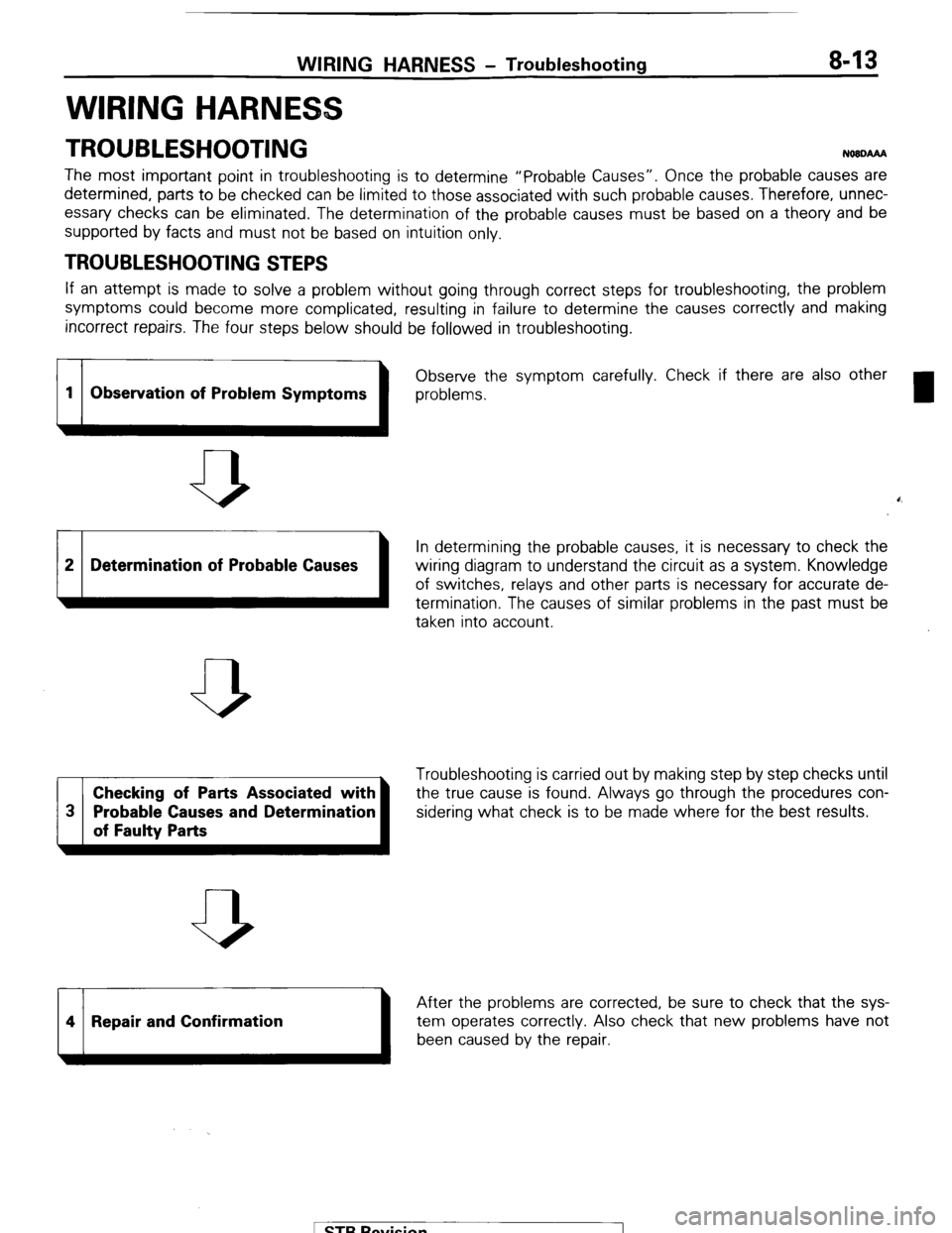
TROUBLESHOOTING NO8DAAA
The most important point in troubleshooting is to determine “Probable Causes”. Once the probable causes are
determined, parts to be checked can be limited to those associated with such probable causes. Therefore, unnec-
essary checks can be eliminated. The determination of the probable causes must be based on a theory and be
supported by facts and must not be based on intuition only.
TROUBLESHOOTING STEPS
If an attempt is made to solve a problem without going through correct steps for troubleshooting, the problem
symptoms could become more complicated, resulting in failure to determine the causes correctly and making
incorrect repairs. The four steps below should be followed in troubleshooting.
1 1 Observe the
1 problems. symptom carefully. Check if there are also other
1 Observation of Problem Symptoms
b
0,
2 Determination of Probable Causes
In determining the probable causes, it is necessary to check the
wiring diagram to understand the circuit as a system. Knowledge
of switches, relays and other parts is necessary for accurate de-
termination. The causes of similar problems in the past must be
taken into account.
Checking of Parts Associated with Troubleshooting is carried out by making step by step checks until
the true cause is found. Always go through the procedures con-
sidering what check is to be made where for the best results.
14 1 Repair and Confirmation
After the problems are corrected, be sure to check that the sys-
1 been caused by the repair, tem operates correctly Also check that new problems have not
1 STB Revision
1
Page 34 of 284

8-14 WIRING HARNESS - Troubleshooting
1680222
Changeover knob 1680224
1680225 1
1680226
INSPECTION
1. Visual and aural checks
Check relay operation, blower motor rotation, light illumina-
tion, etc. visually or aurally. The flow of current is invisible but
can be checked by the operation of the parts.
I
2. Simple checks
For example, if a headlight does not come on and a faulty fuse
or poor grounding is suspected, replace the fuse with a new
one or ground the light to the body by a jumper wire to deter-
mine which part is responsible for the problem.
3. Checking with instruments
Use an appropriate instrument in an adequate range and read
the indication correctly. You must have sufficient knowledge
and experience to handle instruments correctly.
INSPECTION INSTRUMENTS
In inspection, make use of the following instruments.
1. Test lamps
A test lamp consists of a 12 V bulb and lead wires. It is used
to check voltages or shortcircuits.
2. Self-power test lamp
A self-power test lamp consists of a bulb, battery and lead
wires connected in series. It is used to check continuity or
grounding.
,.!‘?i,
,, 6
,‘.’
1 STB Revision