Page 1412 of 1865
1 1 MASTER CYLINDER
3. Secondary piston cup
76G11X-019
Apply brake fluid
t Apply grease
76G11X-020
Piston guide assembly
1. Apply brake fluid to the piston guide cups; then
install them to the piston guide.
2. Install the O-rings to the piston guide.
3. Install the piston guide to the primary piston as-
sembly.
4. Apply brake fluid to the primary piston cup and ap-
ply grease to the piston guide O-rings.
5. Insert the piston guide and primary piston assem-
bly into the cylinder slowly and straight; then fit
them in the position in the cylinder.
76G11X-021
Note
If the piston guide is not easily installed in the
cylinder, use a suitable pipe and tap it to
install.
76G11X-022
11—20
Page 1420 of 1865

1 1 POWER BRAKE UNIT
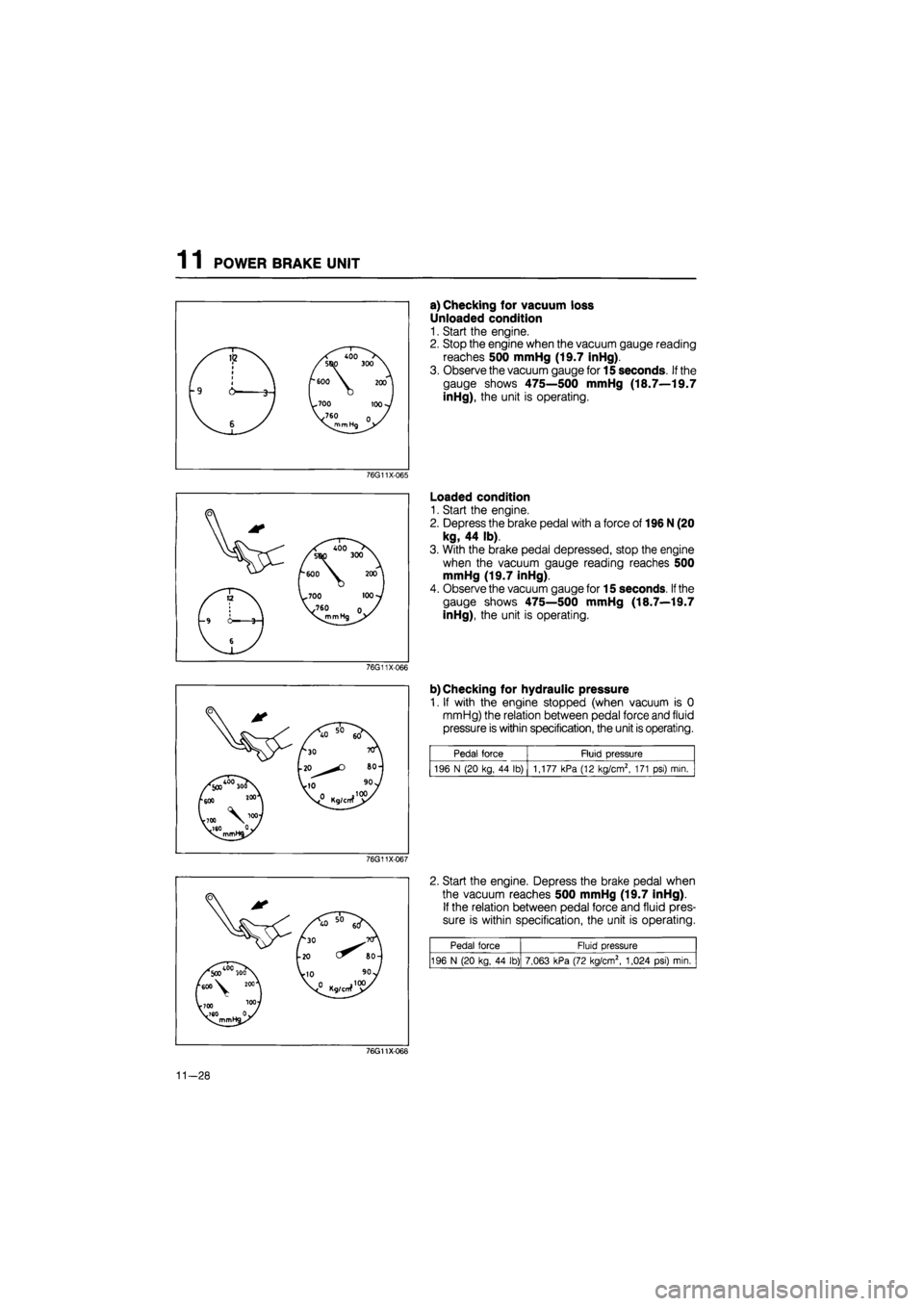
a) Checking for vacuum loss
Unloaded condition
1. Start the engine.
2. Stop the engine when the vacuum gauge reading
reaches 500 mmHg (19.7 inHg).
3. Observe the vacuum gauge for 15 seconds.
If
the
gauge shows 475—500 mmHg (18.7—19.7
inHg), the unit is operating.
76G11X-065
Loaded condition
1. Start the engine.
2. Depress the brake pedal with a force of 196 N (20
kg, 44 lb).
3. With the brake pedal depressed, stop the engine
when the vacuum gauge reading reaches 500
mmHg (19.7 inHg).
4. Observe the vacuum gauge for 15 seconds.
If
the
gauge shows 475—500 mmHg (18.7—19.7
inHg), the unit is operating.
76G11X066
b) Checking for hydraulic pressure
1. If with the engine stopped (when vacuum is 0
mmHg) the relation between pedal force and fluid
pressure is within specification, the unit is operating.
Pedal force Fluid pressure
196 N (20 kg, 44 lb) | 1,177 kPa (12 kg/cm2, 171 psi) mia
76G11X-067
2. Start the engine. Depress the brake pedal when
the vacuum reaches 500 mmHg (19.7 inHg).
If the relation between pedal force and fluid pres-
sure is within specification, the unit is operating.
Pedal force Fluid pressure
196 N (20 kg, 44 lb) 7,063 kPa (72 kg/cm2, 1,024 psi) min.
76G11X068
11-28
Page 1421 of 1865
POWER BRAKE UNIT 1 1
76G11X-034
INSPECTION OF CHECK VALVE
Note (MTX)
The check valve is pressed into the vacuum
hose. There is an arrow on the hose surface
to indicate direction of installation.
Inspection
1. Disconnect the vacuum hose from the engine.
2. Apply suction and pressure to the hose from the
engine side. Check that air flows only toward the
engine.
If the air passes in both directions or not at all, re-
place the check valve (along with the hose).
REMOVAL
Remove in the sequence shown in the figure, referring to removal note for specially marked parts.
1. Fluid level sensor connector
2. Vacuum switch coupler
(RF, RF-CX)
3. Brake pipe
4. Master cylinder
5. Clutch pipe holder
6. Vacuum hose and check
valve
7. Clevis pin
8. Steering shaft
76G11X-069
9. Power brake unit
10. Gasket
11. Locknut
12. Operating lever
11-29
Page 1424 of 1865

1 1 POWER BRAKE UNIT
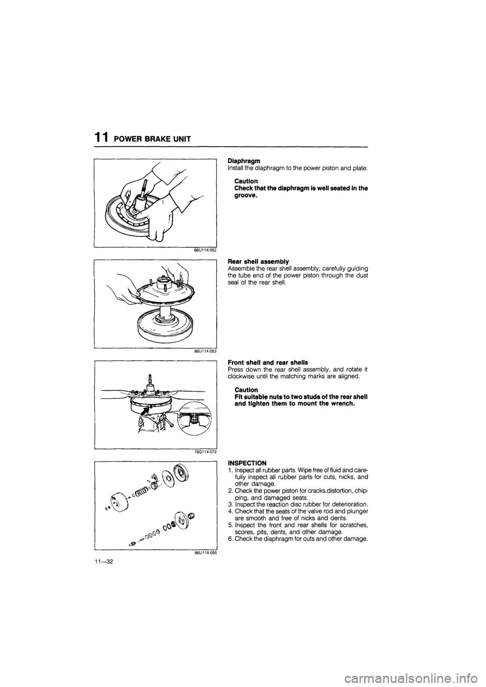
Diaphragm
Install the diaphragm to the power piston and plate.
Caution
Check that the diaphragm is well seated in the
groove.
86U11X-052
Rear shell assembly
Assemble the rear shell assembly; carefully guiding
the tube end of the power piston through the dust
seal of the rear shell.
86U11X-053
Front shell and rear shells
Press down the rear shell assembly, and rotate it
clockwise until the matching marks are aligned.
Caution
Fit suitable nuts to two studs of the rear shell
and tighten them to mount the wrench.
76G11X-072
INSPECTION
1. Inspect all rubber parts. Wipe free of fluid and care-
fully inspect all rubber parts for cuts, nicks, and
other damage.
2. Check the power piston for cracks,distortion, chip-
ping, and damaged seats.
3. Inspect the reaction disc rubber for deterioration.
4. Check that the seats of the valve rod and plunger
are smooth and free of nicks and dents.
5. Inspect the front and rear shells for scratches,
scores, pits, dents, and other damage.
6. Check the diaphragm for cuts and other damage.
11—32
Page 1425 of 1865
POWER BRAKE UNIT 1 1
INSTALLATION
1. Install in the reverse order of removal, referring to installation note for specially marked parts.
2. Tighten all nuts and bolts to the specified torque, referring to torque specifications.
3. After installation:
(1) Add fluid and bleed the air. (Refer to page 11—9.)
(2) Check all parts for fluid leakage.
(3) Make an on-vehicle check of the unit (Refer to page 11—27.)
(4) Verify that the vacuum hose does not contact other parts.
Torque specifications
76G11X-035
1. Vacuum hose and check valve
11—33
Page 1430 of 1865
![MAZDA 626 1987 Workshop Manual
1
1
DUAL PROPORTIONING VALVE
B6U11X-060
DUAL PROPORTIONING VALVE
FUNCTION CHECK
1. Connect
two
pressure gauges [9,810
kPa (100
kg/cm2,1,422 psi)
]
to the brake pipes and adap-
tors
as
MAZDA 626 1987 Workshop Manual
1
1
DUAL PROPORTIONING VALVE
B6U11X-060
DUAL PROPORTIONING VALVE
FUNCTION CHECK
1. Connect
two
pressure gauges [9,810
kPa (100
kg/cm2,1,422 psi)
]
to the brake pipes and adap-
tors
as](/manual-img/28/57059/w960_57059-1429.png)
1
1
DUAL PROPORTIONING VALVE
B6U11X-060
DUAL PROPORTIONING VALVE
FUNCTION CHECK
1. Connect
two
pressure gauges [9,810
kPa (100
kg/cm2,1,422 psi)
]
to the brake pipes and adap-
tors
as
shown
in
the
figure.
Adaptor and flare
nut
tightening torque:
13—22 N m (1.3—2.2 m-kg, 9—16 ft-lb)
Note
Disconnect and connect the brake pipes with
the
SST
(49
0259 770B).
2. Bleed
air
from
the
brake system.
(Refer
to
page 11—9.)
76G11X-043
t 0}
^
£
»
Rear
brake
pressu
kPa
(kg/cm2,
p
>
DO
Rear
brake
pressu
kPa
(kg/cm2,
p
>
DO
TTi
A
B
Master cylinder pressure
kPa
(kg/cm2,
psi)
76G11X-044
Depress the brake pedal until the master cylinder
pressure equals A; then measure rear brake pres-
sure
A'.
Depress the brake pedal again; apply additional
pressure until
A
equals
B;
then measure pressure
B'.
If the measurements
are
not
within specification,
replace
the
valve assembly.
Install the brake pipes to the valve,
and
bleed
air
from
the
brake system.
Specification
Fluid pressure
kPa
(kg/cm2,
psi)
A A' B B'
Except General
LHD
and
RHD
1,962 (20,284)
1,962 ±
196
(20
± 2,
284
± 28)
6,867 (70,995)
3,434 ±
196
(35
± 2,
498
± 28)
General
LHD
and
RHD
2,943 (30,427)
2,943 ±
196
(30
± 2,
427
± 28)
6,867 (70,995) 4,120 ±
196
(42
± 2,
597
± 28)
11-38
Page 1431 of 1865
DUAL PROPORTIONING VALVE 1 1
REMOVAL AND INSTALLATION
1. Remove in the sequence shown in the figure, referring to removal and installation note for specially
marked parts.
2. Install in the reverse order of removal.
3. After installation:
(1) Add brake fluid and bleed the air. (Refer to page 11—9.)
(2) Check the brake lines for fluid leakage.
Caution
Brake fluid will damage painted surfaces. If it does get on a painted surface, wipe it off
immediately.
Except RF-CX
O
76G11X-045
1. Brake pipe 2. Dual proportioning valve
Removal and Installation Note
Brake pipe
Disconnect or connect the brake pipes with the SST.
76G11X-103
11-39
Page 1434 of 1865
1 1 FRONT DISC BRAKE
REMOVAL
1. Loosen the wheel lug nuts.
2. Jack up the front of the vehicle and support it with safety stands.
3. Remove the wheels.
4. Remove in the sequence shown in the figure.
Warning Asbestos dust is a health hazard. Do not blow away brake dust with compressed air.
Caution
Brake fluid will damage painted surfaces. If it does get on a painted surface, wipe it off
immediately.
76G11X-078
1. Flexible hose
2. Caliper assembly
3. V-spring
4. Outer pad and shim
5. Inner pad and shim
6. Guide plate
7. Mounting support
8. Disc plate (Refer to section 9)
11—42