1987 MAZDA 626 brake fluid
[x] Cancel search: brake fluidPage 1488 of 1865
1 1 ANTI-LOCK BRAKE SYSTEM (ABS)
t
2. Bleed air from the system.
3. Depress the brake pedal, and compare the fluid
pressure of the front brake with that of the rear
brake.
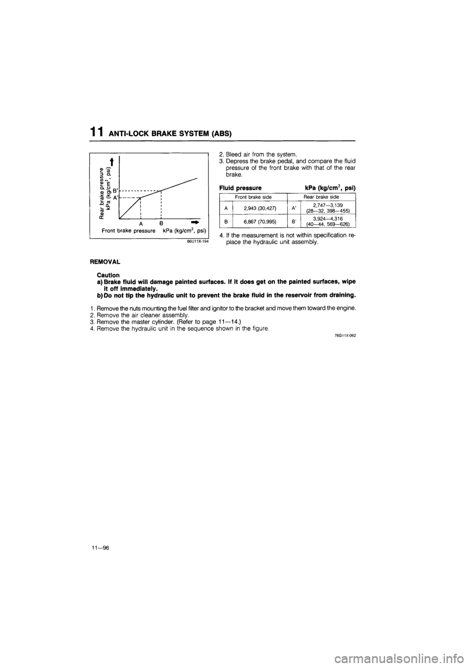
Fluid pressure kPa (kg/cm2, psi)
Front brake side Rear brake side
A 2,943 (30,427)
A'
2,747-3,139
(28-32, 398-455)
A B
B 6,867 (70,995)
B'
3,924-4,316 (40-44, 569-626)
Front brake pressure kPa (kg/cm2, psi) 4. If the measurement is not within specification re-
place the hydraulic unit assembly. 86U11X-194
REMOVAL
Caution
a) Brake fluid will damage painted surfaces. If it does get on the painted surfaces, wipe
it off immediately.
b) Oo not tip the hydraulic unit to prevent the brake fluid in the reservoir from draining.
1. Remove the nuts mounting the fuel filter and ignitor to the bracket and move them toward the engine.
2. Remove the air cleaner assembly.
3. Remove the master cylinder. (Refer to page 11—14.)
4. Remove the hydraulic unit in the sequence shown in the figure.
76G11X-062
11—96
Page 1490 of 1865

1 1 ANTI-LOCK BRAKE SYSTEM (ABS)
INSTALLATION
1. Install in the reverse order of removal.
Before installing the air cleaner assembly, igniter, and fuel filter:
(1) Add brake fluid and bleed air. (Refer to page 11—9.)
(2) Check each part for fluid leakage.
(3) Check the brake fluid level of both the master cylinder reservoir and hydraulic unit reservoir.
2. Tighten all bolts and nuts to the specified torque, referring to torque specifications.
3. After installation:
(1) The sealing reservoir cap (red) is installed on the new hydraulic unit to prevent the brake fluid
from leaking while shipping. Replace it with an original cap (black) after replacing the hydraulic unit.
(2) Check that the hydraulic unit operates properly by testing the pressure reduction. (Refer to page
11-95.)
Torque specifications
11-98
Page 1543 of 1865
1 3 REAR CROSSMEMBER (4WS)
86U13X-096
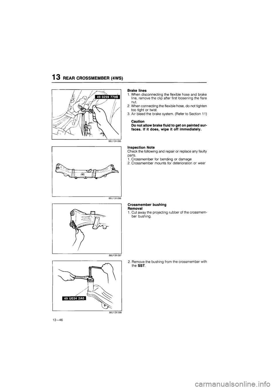
Brake lines
1. When disconnecting the flexible hose and brake
line, remove the clip after first loosening the flare
nut.
2. When connecting the flexible hose, do not tighten
too tight or twist.
3. Air bleed the brake system. (Refer to Section 11)
Caution
Do not allow brake fluid to get on painted sur-
faces. If it does, wipe it off immediately.
Inspection Note
Check the following and repair or replace any faulty
parts.
1. Crossmember for bending or damage
2. Crossmember mounts for deterioration or wear
Crossmember bushing
Removal
1. Cut away the projecting rubber of the crossmem-
ber bushing.
2. Remove the bushing from the crossmember with
the SST.
13—46
Page 1662 of 1865
LOCATION OF UNIT, RELAY AND SWITCH 1 5
LOCATION OF
UNIT,
RELAY AND SWITCH
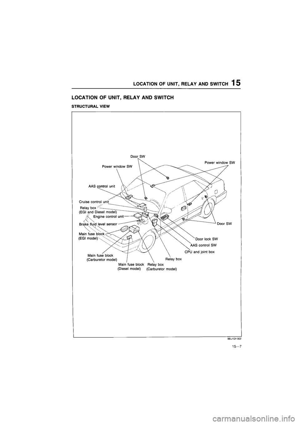
STRUCTURAL VIEW
Door SW
Power window SW
AAS control unit
Cruise control unit
Relay box
(EGI and Diesel model)
Engine control unit
Brake fluid level sensor
Main fuse block
(EGI model)
Main fuse block
(Carburetor model) | \ Relay box
Main fuse block Relay box
(Diesel model) (Carburetor model)
Power window SW
Door SW
Door lock SW
AAS control SW
CPU and joint box
86U15X-002
15-7
Page 1694 of 1865
WARNING AND SENDER 15
Coolant Level Warning Light
OK
Repair harness (Meter
to
coolant level sensor).
76G15X093
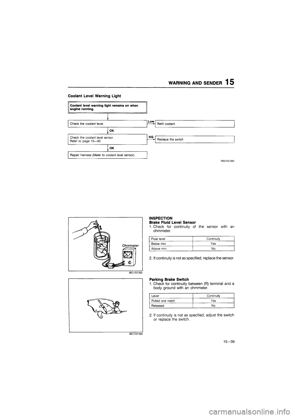
INSPECTION
Brake Fluid Level Sensor
1. Check for continuity of the sensor with an
ohmmeter.
Float level Continuity
Below
min
Yes
Above
min
No
2. If continuity is not as specified, replace the sensor.
86U15X-065
86U14X-066
Parking Brake Switch
1. Check for continuity between (R) terminal and a
body ground with an ohmmeter.
Lever Continuity
Pulled one notch Yes
Released No
2. If continuity is not as specified, adjust the switch
or replace the switch.
15—39
Page 1841 of 1865
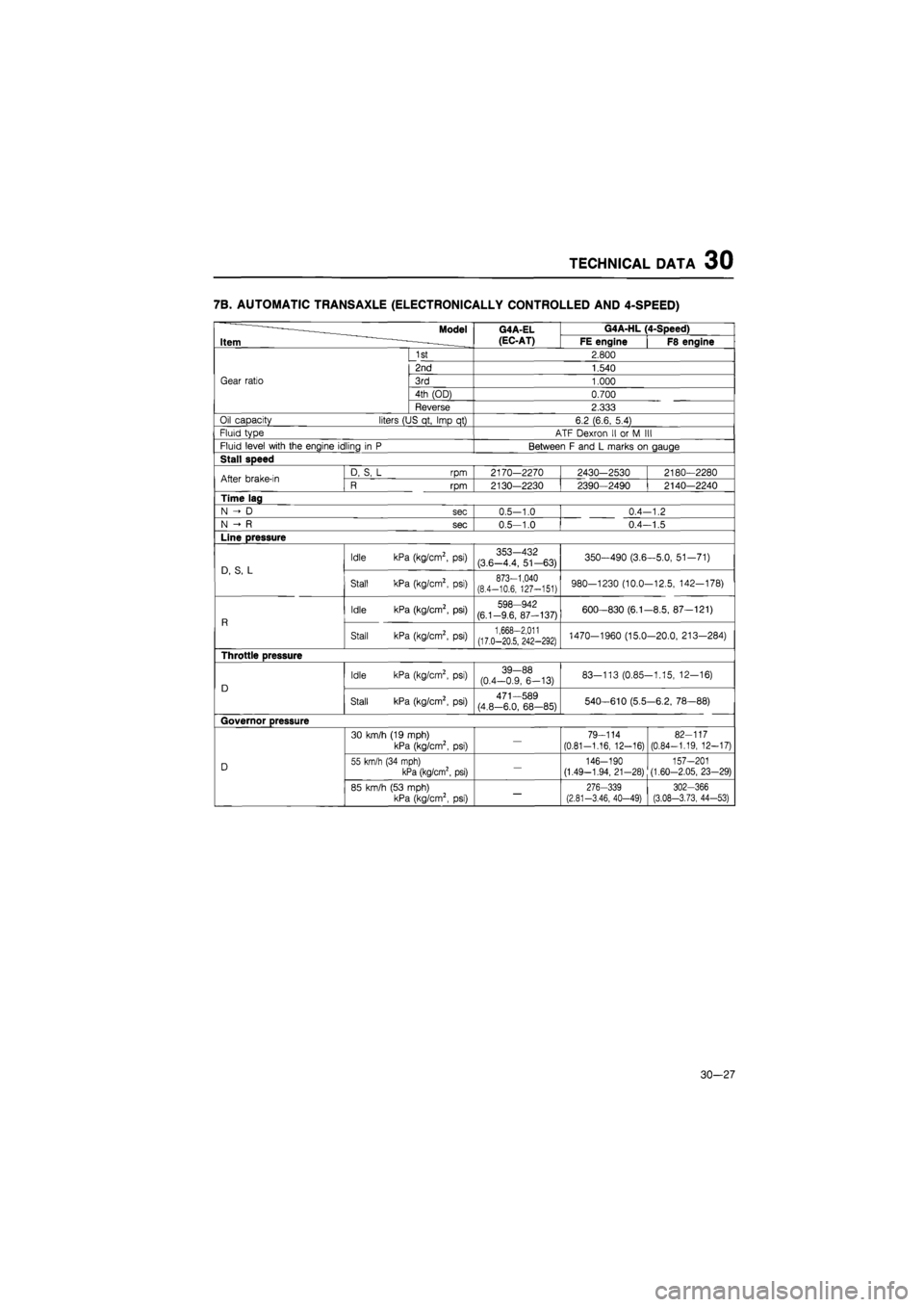
TECHNICAL DATA 30
7B. AUTOMATIC TRANSAXLE (ELECTRONICALLY CONTROLLED AND 4-SPEED)
————Model
Item -————
G4A-EL
(EC-AT)
G4A-HL (4-Speed) ————Model
Item -————
G4A-EL
(EC-AT) FE engine F8 engine
Gear ratio
1st 2.800
Gear ratio
2nd 1.540
Gear ratio 3rd 1.000 Gear ratio
4th (OD) 0.700
Gear ratio
Reverse 2.333
Oil capacity liters (US qt, Imp
qt)
6.2 (6.6, 5.4)
Fluid type ATF Dexron
II or M III
Fluid level with the engine idling
in P
Between
F
and
L
marks
on
gauge
Stall speed
After brake-in D,
S, L rpm
2170-2270 2430-2530 2180—2280 After brake-in R
rpm
2130—2230 2390—2490 2140—2240
Time lag
N
D sec
0.5-1.0 0.4-1.2
N
R sec
0.5-1.0 0.4—1.5
Line pressure
D,
S, L
Idle kPa (kg/cm2,
psi)
353-432 (3.6-4.4, 51—63) 350-490 (3.6-5.0, 51-71)
D,
S, L
Stall kPa (kg/cm2,
psi)
873-1,040 (8.4-10.6, 127-151) 980-1230 (10.0-12.5, 142-178)
R
Idle kPa (kg/cm2,
psi)
598-942 (6.1-9.6, 87-137) 600-830 (6.1-8.5, 87—121)
R
Stall kPa (kg/cm2,
psi)
1,668-2,011 (17.0-20.5, 242-292) 1470-1960 (15.0-20.0, 213-284)
Throttle pressure
D
Idle kPa (kg/cm2,
psi)
39-88 (0.4-0.9, 6-13) 83-113 (0.85-1.15, 12-16)
D
Stall kPa (kg/cm2,
psi)
471—589 (4.8-6.0, 68-85) 540-610 (5.5-6.2, 78—88)
Governor pressure
D
30 km/h (19 mph)
kPa (kg/cm2,
psi) —
79-114
(0.81-1.16, 12-16)
82-117
(0.84-1.19, 12-17)
D 55 km/h (34 mph) kPa (kg/cm2, psi)
—
146-190 (1.49-1.94, 21-28) 157-201 (1.60-2.05, 23-29) D
85 km/h (53 mph) kPa (kg/cm2,
psi) —
276-339 (2.81-3.46, 40-49)
302-366 (3.08-3.73, 44-53)
30-27
Page 1847 of 1865
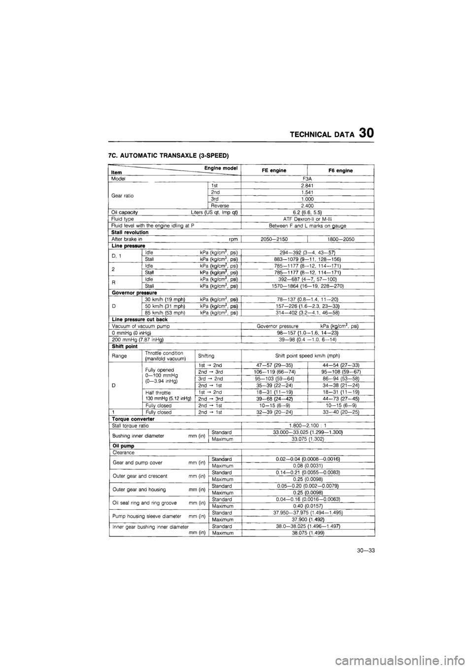
TECHNICAL DATA 30
7C. AUTOMATIC TRANSAXLE (3-SPEED)
Engine model Item FE engine F6 engine
Model F3A
Gear ratio
1st 2.841
Gear ratio 2nd 1.541 Gear ratio 3rd 1.000 Gear ratio
Reverse 2.400
Oil capacity Liters (US qt, Imp
qt)
6.2 (6.6, 5.5)
Fluid type ATF Dexron-ll
or
M-lll
Fluid level with the engine idling
at P
Between
F
and
L
marks
on
gauge
Stall revolution
After brake
in rpm
2050-2150 1800—2050
Line pressure
D,
1
Idle kPa (kg/cm2,
psi)
294-392 (3-4, 43-57) D,
1
Stall kPa (kg/cm2,
psi)
883—1079 (9-11, 128-156)
2 Idle kPa (kg/cm2,
psi)
785-1177 (8—12, 114-171) 2 Stall kPa (kg/cm2,
psi)
785-1177 (8-12, 114—171)
R Idle kPa (kg/cm2,
psi)
392-687 (4-7, 57-100) R Stall kPa (kg/cm2,
psi)
1570-1864 (16-19, 228—270)
Governor pressure
D
30 km/h (19 mph) kPa (kg/cm2,
psi)
78-137 (0.8-1.4, 11-20)
D 50 km/h (31 mph) kPa (kg/cm2, psi) 157-226 (1.6-2.3, 23-33) D
85 km/h
(53
mph) kPa (kg/cm2,
psi)
314-402 (3.2—4.1, 46—58)
Line pressure cut back
Vacuum
of
vacuum pump Governor pressure kPa (kg/cm2,
psi)
0 mmHg
(0
inHg) 98-157 (1.0—1.6, 14—23)
200 mmHg (7.87 inHg) 39-98 (0.4 -1.0, 6-14)
Shift point
Range Throttle condition (manifold vacuum) Shifting Shift point speed km/h (mph)
D
Fully opened 0—100 mmHg (0-3.94 inHg)
1st
- 2nd
47-57 (29-35) 44—54 (27—33)
D
Fully opened 0—100 mmHg (0-3.94 inHg)
2nd
- 3rd
106—119 (66-74) 95—108 (59—67)
D
Fully opened 0—100 mmHg (0-3.94 inHg) 3rd
2nd
95-103 (59-64) 86—94 (53-58)
D
Fully opened 0—100 mmHg (0-3.94 inHg) 2nd -<•
1st
35-39 (22-24) 34-38 (21—24) D
Half throttle 130 mmHg (5.12 inHg)
1st
- 2nd
18-31 (11-19) 18-31 (11-19)
D
Half throttle 130 mmHg (5.12 inHg) 2nd
- 3rd
39-68 (24—42) 44-73 (27—45)
D
Fullv closed 2nd
- 1st
10-15 (6-9) 10—15 (6—9)
1 Fully closed 2nd -»•
1st
32—39 (20—24) 33—40 (20—25)
Torque converter
Stall torque ratio 1.800-2.100
: 1
Bushing inner diameter mm (in) Standard 33.000—33.025 (1.299—1.300) Bushing inner diameter mm (in) Maximum 33.075 (1.302)
Oil pump
Clearance
Gear and pump cover
mm
(in) Standard 0.02—0.04 (0.0008—0.0016) Gear and pump cover
mm
(in) Maximum 0.08 (0.0031)
Outer gear and crescent
mm
(in) Standard 0.14-0.21 (0.0055-0.0083) Outer gear and crescent
mm
(in) Maximum 0.25 (0.0098)
Outer gear and housing
mm
(in) Standard 0.05-0.20 (0.002-0.0079) Outer gear and housing
mm
(in) Maximum 0.25 (0.0098)
Oil seal ring and ring groove
mm
(in) Standard 0.04-0.16 (0.0016-0.0063) Oil seal ring and ring groove
mm
(in) Maximum 0.40 (0.0157)
Pump housing sleeve diameter
mm
(in) Standard 37.950-37.975 (1.494-1.495) Pump housing sleeve diameter
mm
(in) Maximum 37.900 (1.492)
Inner gear bushing inner diameter mm (in)
Standard 38.0-38.025 (1.496—1.497) Inner gear bushing inner diameter mm (in) Maximum 38.075 (1.499)
30—33
Page 1851 of 1865
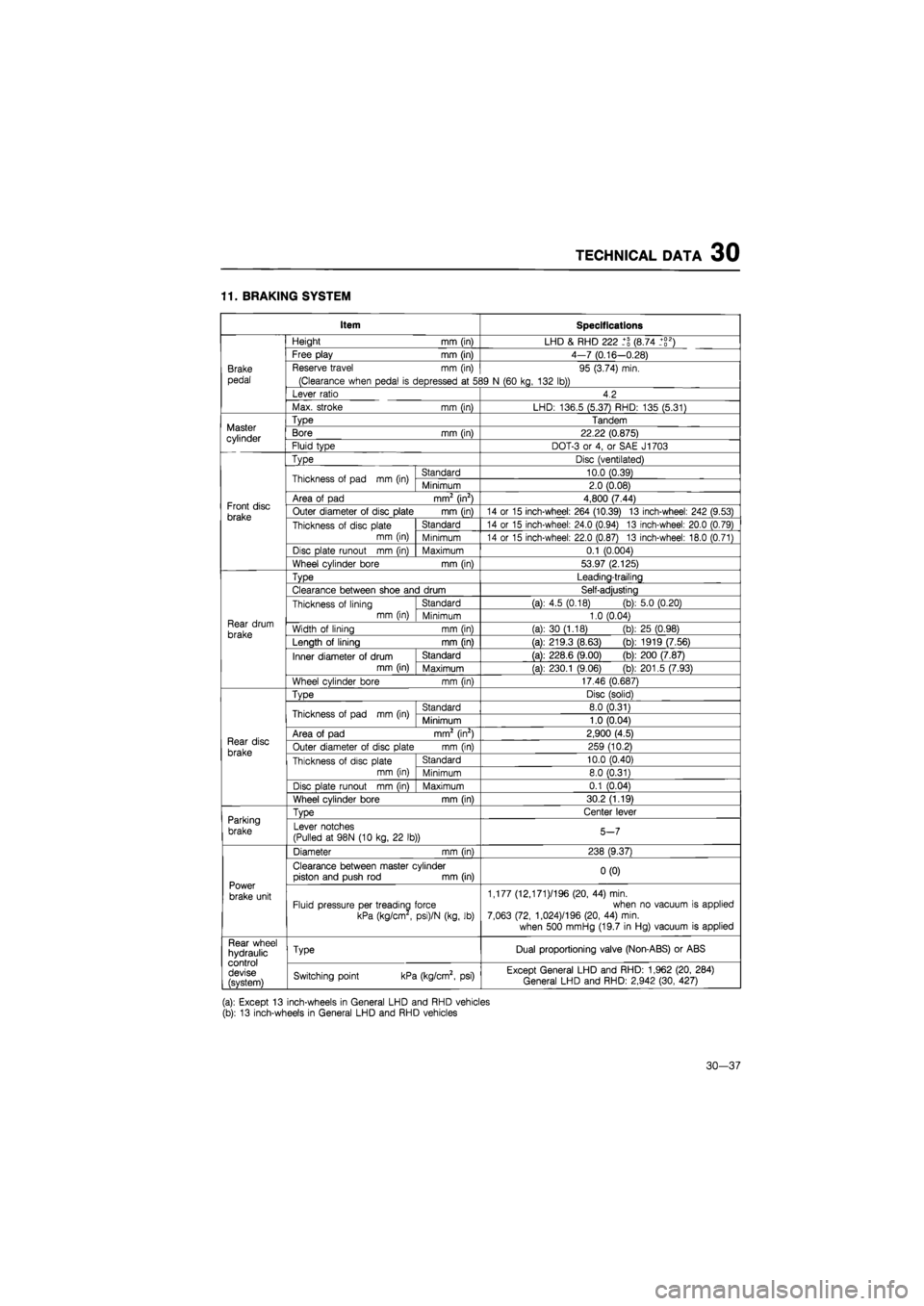
TECHNICAL DATA 30
11. BRAKING SYSTEM
Item Specifications
Brake
pedal
Height
mm
(in) LHD
&
RHD 222 (8.74 _+g2)
Brake
pedal
Free play
mm
(in) 4-7 (0.16—0.28)
Brake
pedal
Reserve travel
mm (in)
(Clearance when pedal
is
depressed
at 5S
95 (3.74) min.
39
N
(60 kg, 132 lb))
Brake
pedal
Lever ratio 4.2
Brake
pedal
Max. stroke
mm (in)
LHD: 136.5 (5.37) RHD: 135 (5.31)
Master cylinder
Type Tandem Master cylinder Bore
mm
(in) 22.22 (0.875) Master cylinder Fluid type DOT-3
or 4, or
SAE J1703
Front disc brake
Type Disc (ventilated)
Front disc brake
Thickness
of
pad
mm (in)
Standard 10.0 (0.39)
Front disc brake
Thickness
of
pad
mm (in)
Minimum 2.0 (0.08)
Front disc brake
Area
of
pad mm2 (in2) 4,800 (7.44) Front disc brake Outer diameter
of
disc plate
mm (in)
14
or 15
inch-wheel: 264 (10.39)
13
inch-wheel: 242 (9.53) Front disc brake Thickness
of
disc plate
mm (in)
Standard 14
or 15
inch-wheel: 24.0 (0.94)
13
inch-wheel: 20.0 (0.79)
Front disc brake Thickness
of
disc plate
mm (in) Minimum 14
or 15
inch-wheel: 22.0 (0.87)
13
inch-wheel: 18.0 (0.71)
Front disc brake
Disc plate runout
mm (in)
Maximum 0.1 (0.004)
Front disc brake
Wheel cylinder bore
mm (in)
53.97 (2.125)
Rear drum
brake
Type Leading-trailing
Rear drum
brake
Clearance between shoe and drum Self-adjusting
Rear drum
brake
Thickness
of
lining mm (in)
Standard (a):
4.5
(0.18) (b): 5.0 (0.20)
Rear drum
brake
Thickness
of
lining mm (in) Minimum 1.0 (0.04) Rear drum
brake Width
of
lining
mm (in)
(a):
30
(1.18)
(b)
25 (0.98) Rear drum
brake Length
of
lining
mm fin)
(a): 219.3 (8.63)
(b)
1919 (7.56)
Rear drum
brake
Inner diameter
of
drum mm (in)
Standard (a): 228.6 (9.00)
(b)
200 (7.87)
Rear drum
brake
Inner diameter
of
drum mm (in) Maximum (a): 230.1 (9.06)
(b)
201.5 (7.93)
Rear drum
brake
Wheel cylinder bore
mm (in)
17.46 (0.687)
Rear disc
brake
TvDe Disc (solid)
Rear disc
brake
Thickness
of
pad
mm (in)
Standard 8.0 (0.31)
Rear disc
brake
Thickness
of
pad
mm (in)
Minimum 1.0 (0.04)
Rear disc
brake
Area
of
pad mm2 (in2) 2,900 (4.5) Rear disc
brake Outer diameter
of
disc plate
mm (in)
259 (10.2) Rear disc
brake Thickness
of
disc plate mm (in)
Standard 10.0 (0.40)
Rear disc
brake Thickness
of
disc plate mm (in) Minimum 8.0 (0.31)
Rear disc
brake
Disc
Dlate runout mm fin)
Maximum 0.1 (0.04)
Rear disc
brake
Wheel cylinder bore
mm (in)
30.2 (1.19)
Parking
brake
TvDe Center lever Parking
brake Lever notches
(Pulled
at
98N
(10
kg,
22 lb))
5-7
Power
brake unit
Diameter
mm (in)
238 (9.37)
Power
brake unit
Clearance between master cylinder piston and push
rod mm
(in) 0(0)
Power
brake unit Fluid pressure per treading force
kPa (kg/cm
,
psi)/N (kg,
lb)
1,177 (12,171 )/196 (20,
44)
min. when
no
vacuum
is
applied 7,063 (72, 1,024)/196 (20,
44)
min.
when 500 mmHg (19.7
in
Hg) vacuum
is
applied
Rear wheel hydraulic control devise (svstem)
Type Dual proportioning valve (Non-ABS)
or
ABS Rear wheel hydraulic control devise (svstem) Switching point kPa (kg/cm2,
psi)
Except General LHD and RHD: 1,962 (20, 284) General LHD and RHD: 2,942 (30, 427)
(a): Except
13
inch-wheels
in
General LHD and RHD vehicles (b):
13
inch-wheels
in
General LHD and RHD vehicles
30—37