Page 778 of 1865

5 STARTER (DIESEL ENGINE, 2.2 KW TYPE)
4BG05X-115
4BG05X-085
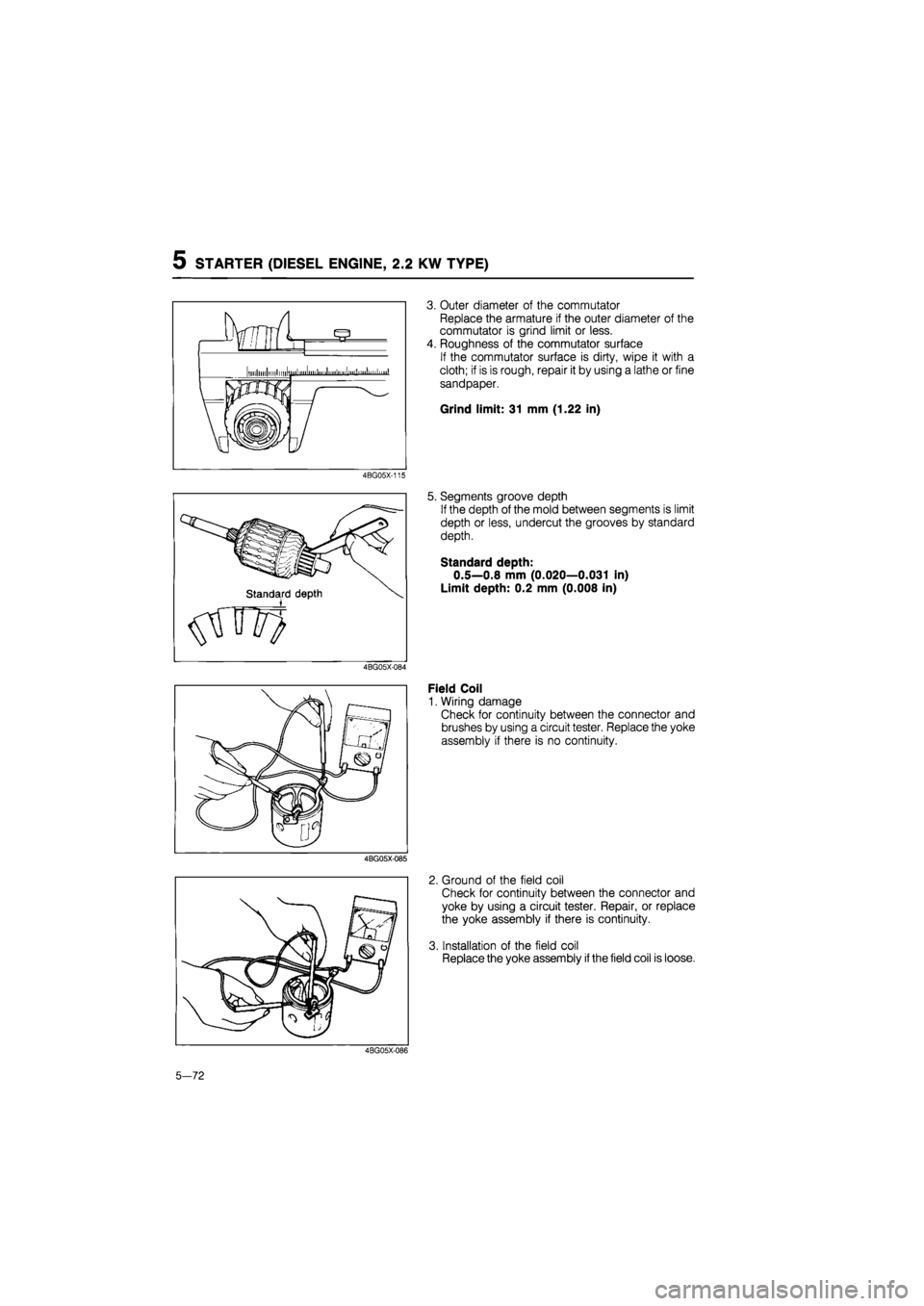
3. Outer diameter of the commutator
Replace the armature if the outer diameter of the
commutator is grind limit or less.
4. Roughness of the commutator surface
If the commutator surface is dirty, wipe it with a
cloth; if is is rough, repair it by using a lathe or fine
sandpaper.
Grind limit: 31 mm (1.22 in)
5. Segments groove depth
If the depth of the mold between segments is limit
depth or less, undercut the grooves by standard
depth.
Standard depth:
0.5—0.8 mm (0.020—0.031 in)
Limit depth: 0.2 mm (0.008 in)
Field Coil
1. Wiring damage
Check for continuity between the connector and
brushes by using a circuit tester. Replace the yoke
assembly if there is no continuity.
2. Ground of the field coil
Check for continuity between the connector and
yoke by using a circuit tester. Repair, or replace
the yoke assembly if there is continuity.
3. Installation of the field coil
Replace the yoke assembly
if
the field coil is loose.
4BG05X-086
5-72
Page 781 of 1865

5 STARTER (DIESEL ENGINE, 2.0 KW TYPE)
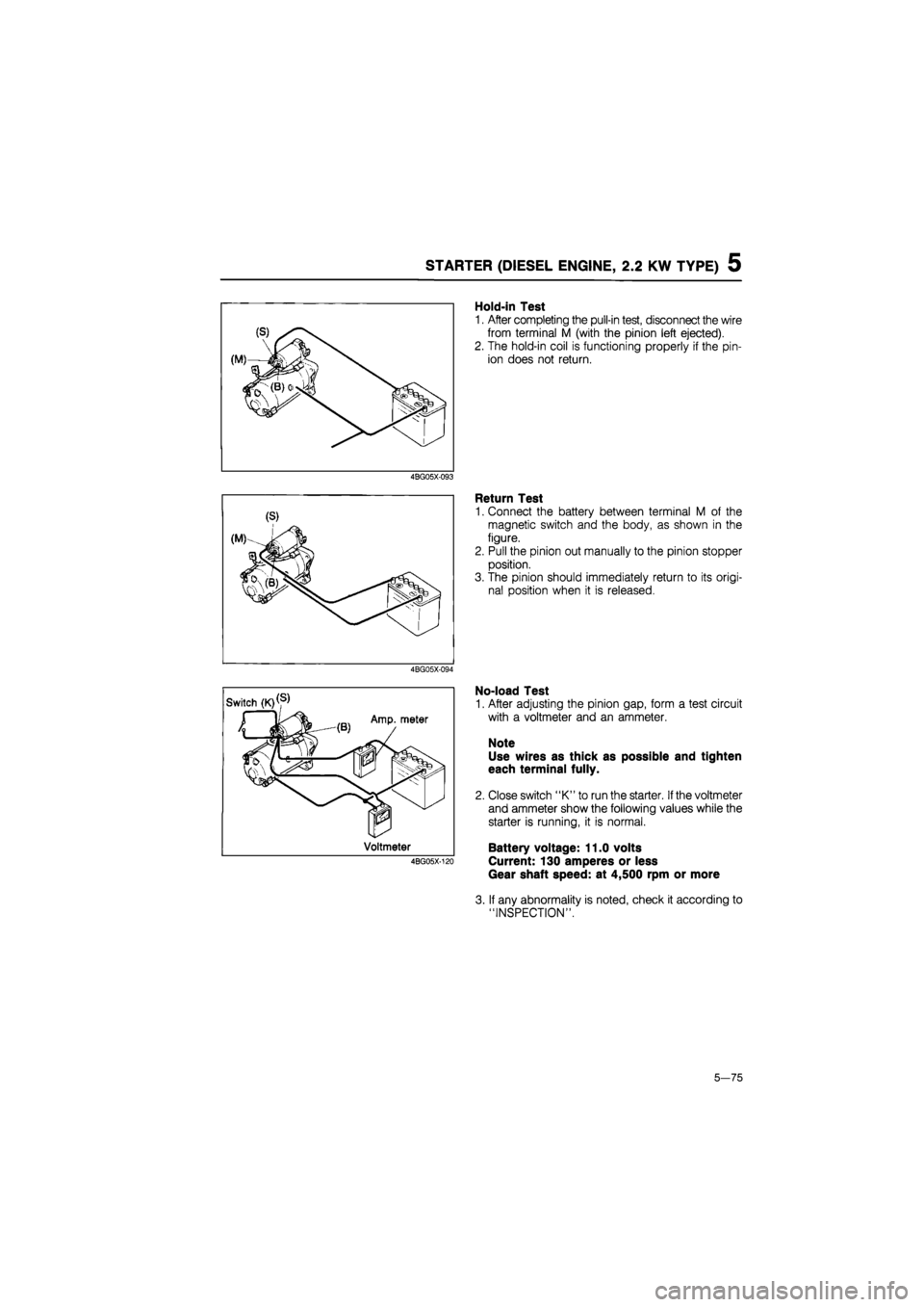
Hold-in Test
1. After completing the pull-in test, disconnect the wire
from terminal M (with the pinion left ejected).
2. The hold-in coil is functioning properly if the pin-
ion does not return.
4BG05X-093
Return Test
1. Connect the battery between terminal M of the
magnetic switch and the body, as shown in the
figure.
2. Pull the pinion out manually to the pinion stopper
position.
3. The pinion should immediately return to its origi-
nal position when it is released.
4BG05X-094
No-load Test
1. After adjusting the pinion gap, form a test circuit
with a voltmeter and an ammeter.
Note
Use wires as thick as possible and tighten
each terminal fully.
2. Close switch "K" to run the starter.
If
the voltmeter
and ammeter show the following values while the
starter is running, it is normal.
Battery voltage: 11.0 volts
Current: 130 amperes or less
Gear shaft speed: at 4,500 rpm or more
3. If any abnormality is noted, check it according to
"INSPECTION".
5—75
Page 789 of 1865

TROUBLESHOOTING GUIDE 6
SPECIFICATIONS
Item Engine model F6 F8 FE FE DOHC RF-N RF-CX
Clutch control type Hydraulic
Clutch cover type Diaphragm spring
General 3,434
(350,770) 3,846
(392,862) 4,316 (440,968) 3,846
(392,862) —
Set load
N (kg, lb) ECE (Except UK) — 4,022
(410,902) 4,611 (470, 1,034) 4,022 (410, 902)
UK — 3,846
(392,862)
4,611 (470,1,034) 4,316
(440,968)
3,846 (392,862) 4,022 (410,902)
Clutch disc Outer diameter mm (in) 200 (7.874) 215 (8.465) 225 (8.858)
Inner diameter mm (in) 130 (5.118) 150 (5.906)
Pressure plate side
General 4.1 (0.16) —
Thickness Pressure plate side
ECE
(Except UK) — 3.8 (0.15)
mm(in)
Pressure plate side UK 4.1 (0.16)13.8 (0.15) 4.1 (0.16) 3.8 (0.15)
Flywheel side 3.5 (0.14)
Type Suspended
Pedal ratio LHD 6.00
Clutch pedal Pedal ratio RHD 5.96
Full stroke mm (in) 135 (5.31)
Height mm (in) 216.5-221.5 (8.524-8.720)
Master cylinder inner diameter mm (in) 15.87 (0.625)
Release cylinder inner diameter mm (in) 19.05 (0.750)
Clutch fluid type DOT-3 or DOT-4, FMVSS 116, or SAE J1703
76G06X-002
TROUBLESHOOTING GUIDE
Problem Possible Cause Remedy Page
Slipping Clutch disc facing worn excessively Replace 6—17 Clutch disc facing surface hardened or oil on Repair or replace 6-17
surface Pressure plate deformed Repair or replace 6-16 Diaphragm spring damaged or weakened Replace 6-16 Insufficient clutch pedal play Adjust 6—4 Clutch pedal does not function smoothly Repair or replace 6—4, 5 Flywheel deformed Repair or replace 6-18
Faulty Excessive runout or deformity of clutch disc Replace 6-17 disengagement Clutch disc splines rusted or worn Remove rust or 6—17 replace Oil on clutch cover facing surface Repair or replace 6-16 Diaphragm spring weakened Replace 6-16
Excessive clutch pedal play Adjust 6—4, 5
Insufficient clutch fluid Add fluid 6-4
Leakage of clutch fluid Reoair or reDlace —
Clutch vibrates Oil on clutch disc facing surface Repair or replace 6-17 when starting Torsion spring weakened Replace 6-17 Clutch disc facing surface hardened or deformed Repair or replace 6-17
Clutch disc facing rivets loose Replace 6-17 Pressure plate deformed Replace 6-16
Flywheel surface hardened or deformed Repair or replace 6-18
Loose or worn engine mount Tighten or replace —
Clutch pedal Pedal shaft not properly lubricated lubricate or replace 6-5 does not func-tion smoothlv
Abnormal noise Clutch release bearing damaged Replace 6—17 Poor lubrication of clutch release bearing sleeve Lubricate or replace 6-17
Torsion spring weakened Replace 6-17
Excessive crankshaft end play Repair Refer to Section 1 Pilot bearing worn or damaged by heat Replace 6-16
Worn pivot points of release fork • Reoair or replace 6-18
76G06X-003
6-3
Page 810 of 1865
7A OUTLINE
SPECIFICATIONS
•Engine model
Item ——
FE DOHC F6 FE 12-valve
FE 8-valve F8 RF-N RF-CX •Engine model
Item —— Leaded Unleaded F6 FE 12-valve Carb. Fl F8 RF-N RF-CX
Transaxle control Floor shift
Synchromesh system Forward synchromesh, Reverse selective sliding and synchromesh
Gear ratio
1st 3.307
Gear ratio
2nd 1.833
Gear ratio 3rd 1.310 1.233 1.161 Gear ratio
4th 1.030 0.970 0.914 0.861
Gear ratio
5th 0.837 0.795 0.755 0.680
Gear ratio
Reverse 3.166
Final gear ratio 4.105 3.850 4.105 3.850 4.105
Oil Type
ATF: DEXRON-II Above -18°C (0°F): API: GL-4 or GL-5 SAE 80W-90 or SAE 90 Oil
Capacity 3.35 liters (3.6 US qt, 3.9 Imp qt)
76G07A-004
7A—4
Page 812 of 1865

7A ON-VEHICLE MAINTENANCE
61G07X-189
61G07X-190
61G07X-191
ON-VEHICLE MAINTENANCE
TRANSAXLE OIL
Inspection
1. Park the vehicle on level ground.
2. Remove the speedometer cable dust cover, and
disconnect the cable from the speedometer driv-
en gear.
3. After removing the bolt, pull the gear case to re-
move
it
from the housing. (Insert a flat-tipped screw-
driver between the speedometer gear case and
the clutch housing, and use
it
to pry the gear case
loose if necessary.)
4. Check that the oil level is between the "F" and "L".
5. If not, add the necessary amount of the specified
oil through the gear case hole.
Replacement
1. Park the vehicle on level ground.
2. Remove the speedometer driven gear.
(See "Inspection" section above.)
3. Remove the drain plug, and drain the oil.
4. Replace the drain plug, and add the necessary
amount of the specified oil through the speedom-
eter gear case hole.
Specified oil
Type
ATF: DEXRON II
Above -18°C (0°F):
API: GL-4 or GL-5
SAE 80W-90 or SAE 90
Capacity:
3.35 liters (3.6 US qt, 3.0 Imp qt)
76G07A-006
7A—6
Page 815 of 1865
ON-VEHICLE MAINTENANCE 7A
13. Adjust and tighten the stabilizer.
Tightening torque:
16—23 Nm (1.6—2.3 m-kg, 12—17 ft-lb)
Dimension: 20.1 mm (0.79 in)
86U07A-016
76G07A-007
14. Install the drain plug.
Tightening torque:
39—59 Nm (4.0—6.0 m-kg, 29—43 ft-lb)
15. Install the wheel.
Tightening torque:
88—118 Nm (9.0—12.0 m-kg, 65—87 ft-lb)
16. Add the correct quantity of the specified oil.
Type: A.T.F.: DEXRON II
Above -18°C (0°F):
API: GL-4 or GL-5
SAE 80W-90 or SAE 90
Capacity: 3.35 liters (3.6 US qt, 3.0 Imp qt)
7A—9
Page 863 of 1865
INSTALLATION 7A
25. Install the grounds to the transaxle case.
Tightening torque:
8—11 N-m (80—115 cm-kg, 69—100 in-lb)
26. Connect the speedometer cable.
76G07A-067
76G07A-068
76G07A-069
76G07A-070
27. Install the intercooler pipe and hose. (RF-CX)
Tightening torque:
19—26 Nm (1.9—2.6 m-kg, 14—19 ft-lb)
28. Install the brake vacuum pipe. (RF-CX)
Tightening torque:
8—11
N
m (80—110 cm-kg, 69—95 in-lb)
29. Connect the brake vacuum hose. (RF-CX)
30. Install the air cleaner assembly and connect the
air flow meter connector.
Tightening torque:
16—27 Nm (1.6—2.8 m-kg, 12—20 ft-lb)
31. Connect the distributor lead.
32. Connect the main fuse block.
Tightening torque:
8—11 N-m (80—110 cm-kg, 69—95 in-lb)
33. Install the battery carrier and battery.
34. Add the correct quantity of the specified transaxle
oil.
Specified
Type
A.T.F.: DEXRON II
Above 0°F:
API: GL-4 or GL-5
SAE 80W-90 or SAE 90
Capacity:
3.35 liters (3.6 US qt, 3.0 Imp qt)
7A-57
Page 879 of 1865

TROUBLESHOOTING (G4A-EL) 7B
By following the above seven steps, the cause of the problem should be located.
As another guide to faster location of the causes of problems, the Quick Diagnosis Chart is included
at pages 7B—13, 14.
In this chart, a circle is used to indicate the components that might be the cause of trouble for 23
types of problems. It is only necessary to check those components indicated by circles, at each step
cf the troubleshooting process, in order to quickly locate the cause of the problem.
Quick Diagnosis Chart
The Quick Diagnosis Chart shows various problems and the relationship of various components that
might be the cause of the problem.
1. Components indicated in the "Self-Diag." column are diagnosed by the EC-AT control unit self-
diagnosis function.
The EC-AT Tester can be used for easy retrieval of these signals.
2. Components indicated in the "Adjustment" column indicate that there is a possibility that the prob-
lem may be the result of an incorrect adjustment.
Check the adjustment of each component, and readjust if necessary.
3. Input and outout signals of the EC-AT control unit for the components indicated in the "EC-AT
TESTER" column can be easily checked by using of the EC-AT Tester.
4. Components indicated in the "Stall Test" column can be checked for malfunction by the results
of the stall test.
5. Components indicated in the "Time Lag Test" column can be checked for malfunction by the results
of the time lag test.
6. Components indicated in the "Oil Pressure Test" column can be checked for malfunction by the
results of the oil pressure test.
7. Components indicated in the "Road Test" column can be checked for malfunction by the results
of the road test.
8. The checking, adjusting, repair or replacement procedures for each component is described in the
page(s) noted in the "Reference Page" column.
7B—13