1987 MAZDA 626 oil type
[x] Cancel search: oil typePage 907 of 1865

TROUBLESHOOTING (G4A-HL) 7B
TROUBLESHOOTING (G4A-HL)
GENERAL NOTE
In the event of a problem with the automatic transaxle, the cause may be in the engine, power train,
hydraulic control system, or electrical control system.
When troubleshooting, therefore, it is recommended to begin from those points that can be judged
quickly and easily. The recommended troubleshooting sequence is described below.
STEP 4: TIME LAG TEST
Check time lag of oil pressure supply
STEP 6: OIL PRESSURE TEST Check line, throttle, and governor pressures
This step checks conditions surrounding the automatic
transaxle.
This step checks the electrical control system.
• Function of the electrical control system
• Components
This step checks the power train. • Friction element slipping • Torque converter capacity
This step checks operation of the hydraulic control system. • Accumulators • Friction elements slipping • Regulating valves
This step checks functions of the electric control system and
hydraulic control system.
This step checks major points of the hydraulic control system.
• Oil pump • Line pressure control • Throttle pressure control
• Governer pressure control
STEP 5: ROAD TEST Check items on road test
• Shift point • Shift schedule
• Kick-down • Shift shock • Lock-up and overdrive inhibition
By following the above 6 steps, the cause of the problem should be located.
As another guide to faster location of the causes of problems, the Quick Diagnosis Chart is included
at pages 7B—42, 43.
In this chart, a circle is used to indicate the components that might be the cause of trouble for 20
types of problems. It is only necessary to check those components indicated by circles, at each step
of the troubleshooting process, in order to quickly locate the cause of the problem.
76G07B-040
7B—41
Page 1080 of 1865
7B ASSEMBLY
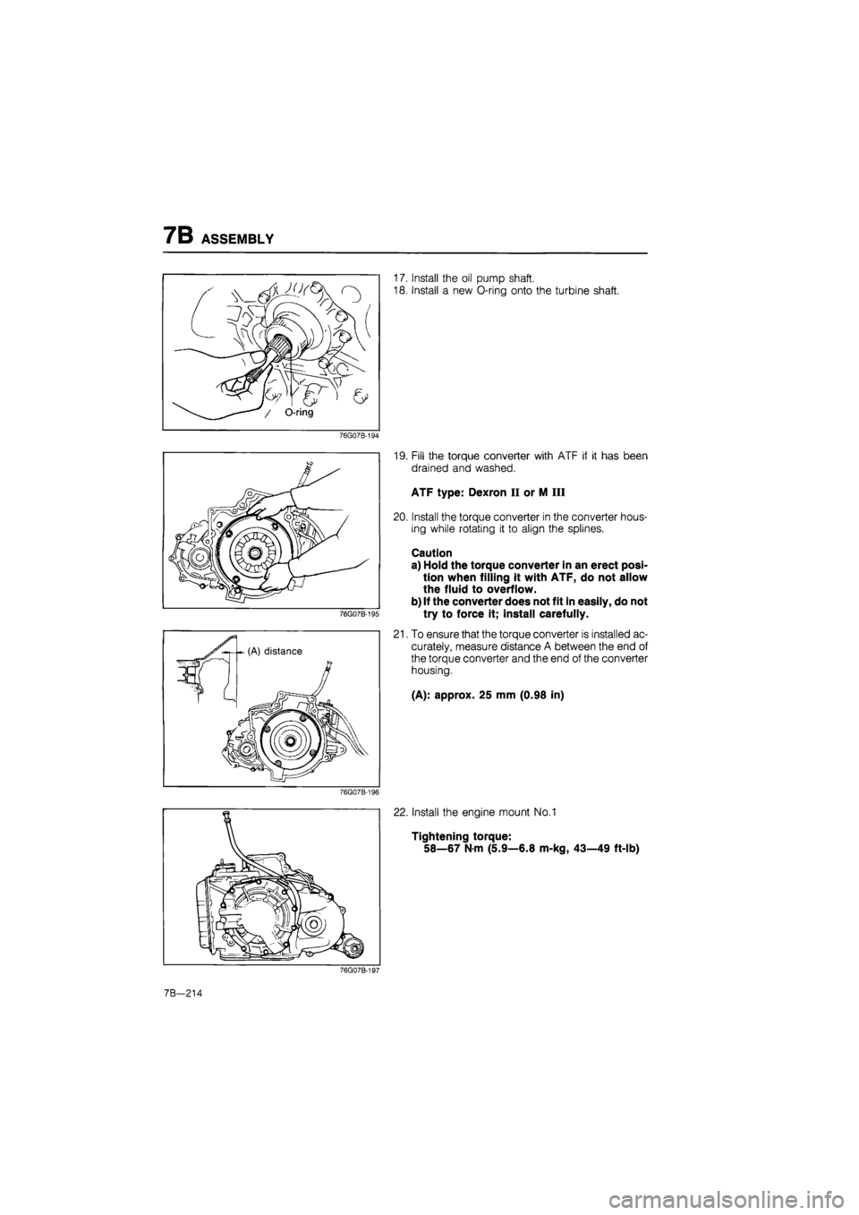
/ O-ring
17. Install the oil pump shaft.
18. Install a new O-ring onto the turbine shaft.
76G07B-194
76G07B-195
19. Fill the torque converter with ATF if it has been
drained and washed.
ATF type: Dexron II or M III
20. Install the torque converter in the converter hous-
ing while rotating it to align the splines.
Caution
a) Hold the torque converter in an erect posi-
tion when filling it with ATF, do not allow
the fluid to overflow.
b) If the converter does not fit in easily, do not
try to force it; install carefully.
21. To ensure that the torque converter is installed ac-
curately, measure distance A between the end of
the torque converter and the end of the converter
housing.
(A): approx. 25 mm (0.98 in)
22. Install the engine mount No.1
Tightening torque:
58—67
N
m (5.9—6.8 m-kg, 43—49 ft-lb)
76G07B-197
7B-214
Page 1122 of 1865
7C TROUBLESHOOTING
TROUBLESHOOTING
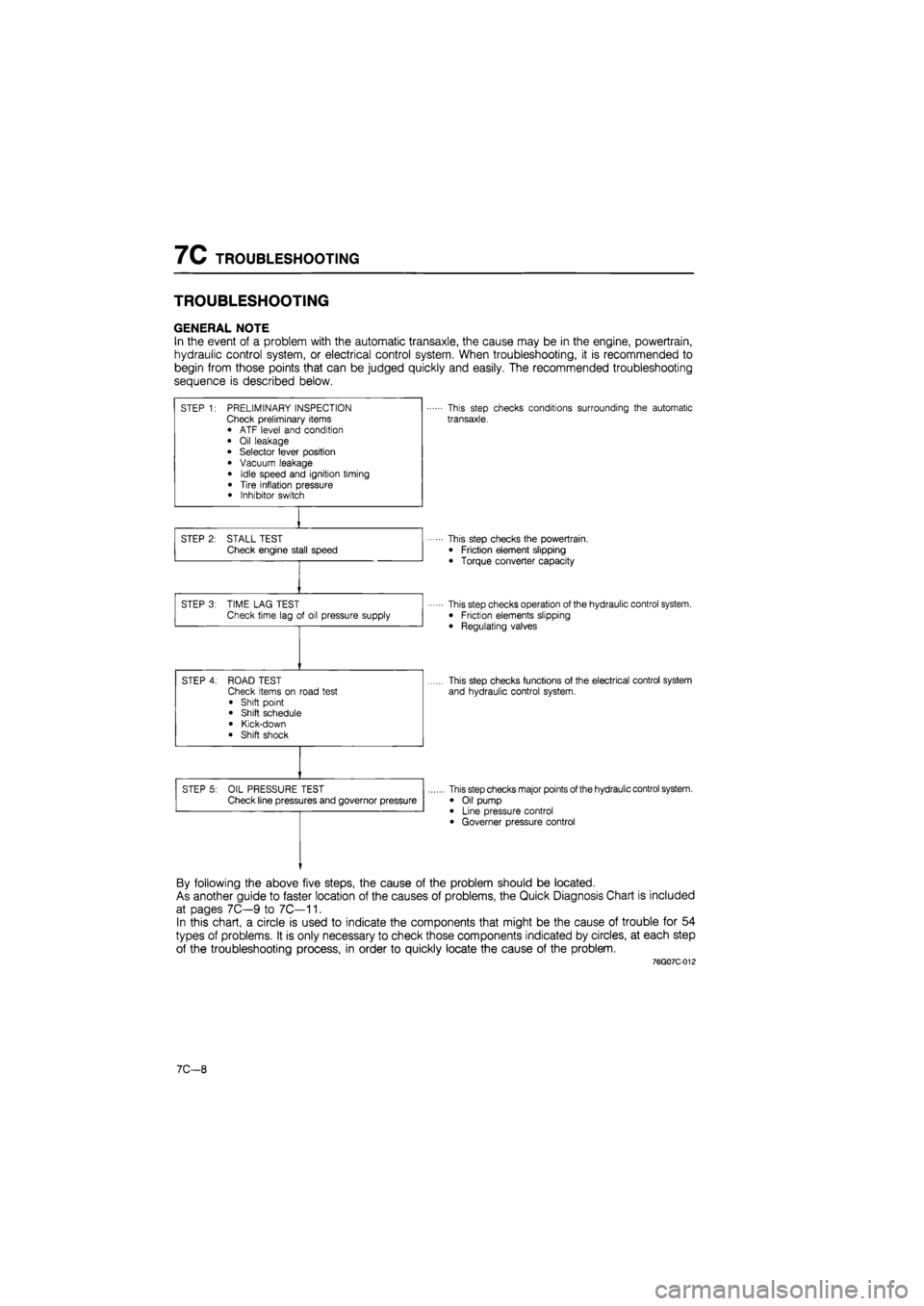
GENERAL NOTE
In the event of a problem with the automatic transaxle, the cause may be in the engine, powertrain,
hydraulic control system, or electrical control system. When troubleshooting, it is recommended to
begin from those points that can be judged quickly and easily. The recommended troubleshooting
sequence is described below.
STEP 1: PRELIMINARY INSPECTION Check preliminary items • ATF level and condition
• Oil leakage • Selector lever position
• Vacuum leakage
• Idle speed and ignition timing
• Tire inflation pressure • Inhibitor switch
This step checks conditions surrounding the automatic
transaxle.
STEP 2: STALL TEST Check engine stall speed This step checks the powertrain.
• Friction element slipping
• Torque converter capacity
STEP 3: TIME LAG TEST Check time lag of oil pressure supply This step checks operation of the hydraulic control system. • Friction elements slipping
• Regulating valves
STEP 4: ROAD TEST Check items on road test
• Shift point • Shift schedule
• Kick-down • Shift shock
This step checks functions of the electrical control system
and hydraulic control system.
STEP 5: OIL PRESSURE TEST Check line pressures and governor pressure This step checks major points of the hydraulic control system.
• Oil pump • Line pressure control • Governer pressure control
By following the above five steps, the cause of the problem should be located.
As another guide to faster location of the causes of problems, the Quick Diagnosis Chart is included
at pages 7C—9 to 7C—11.
In this chart, a circle is used to indicate the components that might be the cause of trouble for 54
types of problems. It is only necessary to check those components indicated by circles, at each step
of the troubleshooting process, in order to quickly locate the cause of the problem.
76G07C-012
7C—8
Page 1296 of 1865

1 0 TROUBLESHOOTING GUIDE
POWER STEERING
Problem Possible cause Remedy Page
Hard steering
Loose
or
damaged belt Low fluid level,
or air in
fluid Leakage
of
fluid
Malfunctioning electrical system* Insufficient oil pump pressure Improperly adjusted wheel alignment Malfunctioning steering gear Linkage ball joint not operating smoothly
Adjust
or
replace Add fluid
or
bleed
air
Repair
or
replace Repair
or
replace Repair
or
replace Refer
to
Section
13
Repair
or
replace Replace
10—12 10-11 10-13 10-87 10-16
10—28,
37
10-18
Poor return
Insufficient tire pressure
Improperly adjusted wheel alignment
Ball-joint not operating smoothly
Steering shaft contacting something
Refer
to
Section
12
Refer
to
Section
13
Replace
Repair
10-20 10-21
Excessive play
Loose gear box housing mounting bolts Worn linkage
or
tie-rod ball joint Worn lower ball joint Worn
or
damaged steering joint Worn rack and pinion gear
Tighten Replace
Refer
to
Section
13
Replace
Replace
10—30
10—18
10—21
10-58,
75
Steering wheel
vibrates
Insufficient tire pressure Damaged
or
unbalanced wheel Improperly adjusted wheel alignment Loose gear box housing mounting bolts Incorrect pinion preload adjustment Worn ball joints
Loose shock absorber mounting Malfunctioning shock absorber
Refer
to
Section
12
Refer
to
Section
13
Refer
to
Section
13
Tighten Adjust
Replace Refer
to
Section
13
Refer
to
Section
13
10-30 10-72,
81
10—18
Steering wheel
pulls
Unevenly worn tires
Incorrect tire pressure
Dragging brake
Improperly adjusted wheel alignment
Refer
to
Section
12
Refer
to
Section
12
Refer
to
Section
11
Refer
to
Section
13 —
Excessively light
steering at high
speed*
Malfunctioning electrical system Repair
or
replace 10-87
*... Only
for
electronically
-
controlled type
76G10X-002
10—8
Page 1299 of 1865
ON-VEHICLE MAINTENANCE 1 0
"{krf
'"""^JlW^M 1
V
^A-X
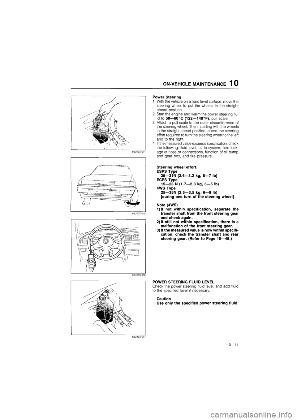
Power Steering
1.
86U10X-014
86U10X-015
With the vehicle on a hard level surface, move the
steering wheel to put the wheels in the straight
ahead position.
Start the engine and warm the power steering flu-
id to 50—60°C (122—140°F), pull scale.
Attach a pull scale to the outer circumference of
the steering wheel. Then, starting with the wheels
in the straight-ahead position, check the steering
effort required to turn the steering wheel to the left
and to the right.
If the measured value exceeds specification, check
the following: fluid level, air in system, fluid leak-
age at hose or connections, function of oil pump
and gear box, and tire pressure.
Steering wheel effort:
ESPS Type
25—31N (2.6—3.2 kg, 6—7 lb)
ECPS Type
15—23 N (1.7—2.3 kg, 3—5 lb)
4WS Type
25—35N (2.5—3.5 kg, 6—8 lb)
[during one turn of the steering wheel]
Note (4WS)
1)lf not within specification, separate the
transfer shaft from the front steering gear
and check again.
2) If still not within specification, there is a
malfunction of the front steering gear.
3) If the measured value is now within specifi-
cation, check the transfer shaft and rear
steering gear. (Refer to Page 10—45.)
86U10X-016
POWER STEERING FLUID LEVEL
Check the power steering fluid level, and add fluid
to the specified level if necessary.
Caution
Use only the specified power steering fluid.
86U10X-017
10—11
Page 1301 of 1865
ON-VEHICLE MAINTENANCE 1 0
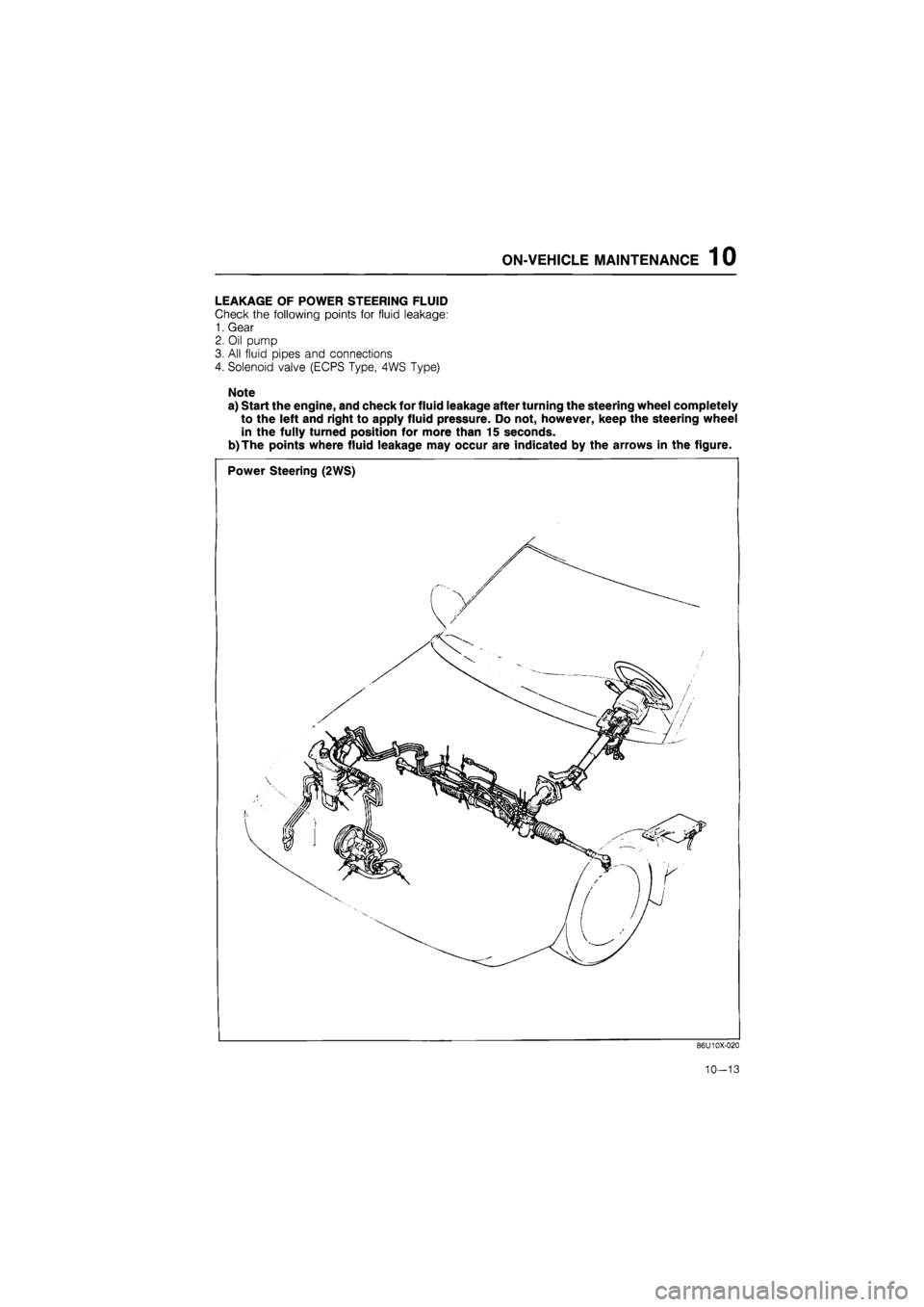
LEAKAGE OF POWER STEERING FLUID
Check the following points for fluid leakage:
1. Gear
2. Oil pump
3. All fluid pipes and connections
4. Solenoid valve (ECPS Type, 4WS Type)
Note
a) Start the engine, and check for fluid leakage after turning the steering wheel completely
to the left and right to apply fluid pressure. Do not, however, keep the steering wheel
in the fully turned position for more than 15 seconds.
b)The points where fluid leakage may occur are indicated by the arrows in the figure.
Power Steering (2WS)
86U10X-020
10-13
Page 1496 of 1865
WHEELS AND TIRES 1 2
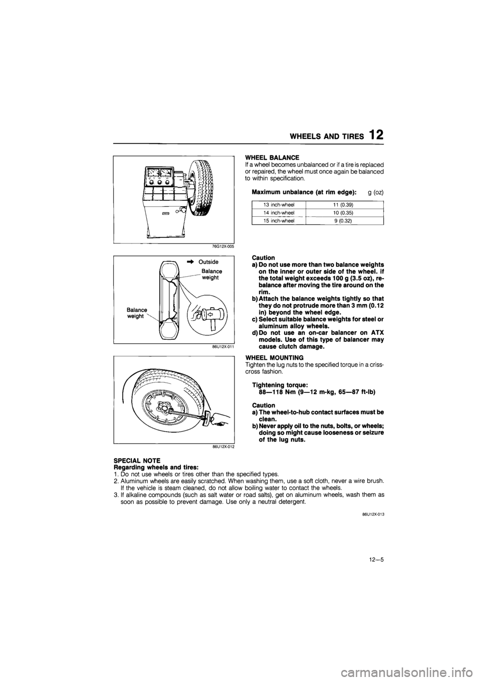
WHEEL BALANCE
If a wheel becomes unbalanced or if a tire is replaced
or repaired, the wheel must once again be balanced
to within specification.
Maximum unbalance (at rim edge): g (oz)
13 inch-wheel 11 (0.39)
14 inch-wheel 10 (0.35)
15 inch-wheel 9 (0.32)
76G12X-005
Balance
weight
Outside
Balance
weight
86U12X-011
Caution
a) Do not use more than two balance weights
on the inner or outer side of the wheel, if
the total weight exceeds 100 g (3.5 oz), re-
balance after moving the tire around on the
rim.
b) Attach the balance weights tightly so that
they do not protrude more than 3 mm (0.12
in) beyond the wheel edge.
c) Select suitable balance weights for steel or
aluminum alloy wheels.
d)Do not use an on-car balancer on ATX
models. Use of this type of balancer may
cause clutch damage.
WHEEL MOUNTING
Tighten the lug nuts to the specified torque in a criss-
cross fashion.
Tightening torque:
88—118 N-m (9—12 m-kg, 65—87 ft-lb)
Caution
a) The wheel-to-hub contact surfaces must be
clean.
b) Never apply oil to the nuts, bolts, or wheels;
doing so might cause looseness or seizure
of the lug nuts.
86U12X-012
SPECIAL NOTE
Regarding wheels and tires:
1. Do not use wheels or tires other than the specified types.
2. Aluminum wheels are easily scratched. When washing them, use a soft cloth, never a wire brush.
If the vehicle is steam cleaned, do not allow boiling water to contact the wheels.
3. If alkaline compounds (such as salt water or road salts), get on aluminum wheels, wash them as
soon as possible to prevent damage. Use only a neutral detergent.
86U12X-013
12-5
Page 1501 of 1865
13 OUTLINE
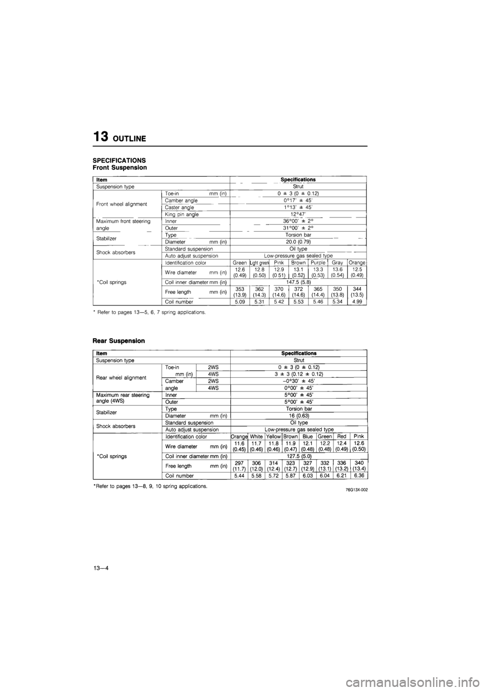
SPECIFICATIONS
Front Suspension
Item Specifications
Suspension type Strut
Toe-in mm (in) 0 ± 3 (0 ± 0.12)
Front wheel alignment Camber angle 0C 17' ± 45' Front wheel alignment Caster angle 1c 13' ± 45'
King pin angle 12°47'
Maximum front steering Inner 36 °00' ± 2°
angle Outer 31 °00' ± 2°
Stabilizer Type Torsion bar Stabilizer Diameter mm (in) 20.0 (0.79)
Shock absorbers Standard suspension Oil type Shock absorbers Auto adjust suspension Low-pressure gas sealed type
Identification color Green Light green Pink Brown Purple Gray Orange
Wire diameter mm (in) 12.6 (0.49) 12.8 (0.50)
12.9
(0.51) 13.1 (0.52)
13.3 (0.53)
13.6
(0.54) 12.5 (0.49)
*Coil springs Coil inner diameter mm (in) 147.5 (5.8)
Free length mm (in) 353 (13.9)
362 (14.3) 370 (14.6) 372 (14.6) 365 (14.4)
350
(13.8)
344
(13.5)
Coil number 5.09 5.31 5 42 5.53 5.46 5.34 4.99
* Refer to pages 13—5, 6, 7 spring applications.
Rear Suspension
Item Specifications
SusDension tvDe Strut
Rear wheel alignment
Toe-in
mm (in)
2WS 0 ± 3 (0 ± 0.12)
Rear wheel alignment
Toe-in
mm (in) 4WS 3 ± 3 (0.12 ± 0.12) Rear wheel alignment Camber
anale
2WS -0°30' ± 45' Rear wheel alignment Camber
anale 4WS 0°00' ± 45'
Maximum rear steering angle (4WS) Inner 5°00' ± 45' Maximum rear steering angle (4WS) Outer 5°00' ± 45'
Stabilizer TvDe Torsion bar Stabilizer Diameter mm (in) 16 (0.63)
Shock absorbers Standard susDension Oil tvDe Shock absorbers Auto adiust suspension Low-pressure c las sealed type
'Coil springs
Identification color Orange White Yellow Brown Blue Green Red Pink
'Coil springs
Wire diameter mm (in) 11.6
(0.45)
11.7 (0.46) 11.8
(0.46)
11.9 (0.47)
12.1
(0.48)
12.2
(0.48)
12.4 (0.49) 12.6 (0.50)
'Coil springs Coil inner diameter mm (in) 127.5 (5.0) 'Coil springs
Free length mm (in) 297 (11.7) 306 (12.0)
314 (12.4) 323 (12.7) 327 (12.9) 332 (13.1) 336 (13.21 340 (13.4)
'Coil springs
Coil number 5.44 5.58 5.72 5.87 6.03 6.04 6.21 6.36
'Refer to pages 13—8, 9, 10 spring applications.
13—4