Page 1159 of 1865
DISASSEMBLY 7C
DISASSEMBLY - STEP 3
76G07C-100
1. Oil pipe
2. Parking pawl assembly
3. Drum hub assembly
4. One-way clutch inner race
assembly
5. One-way clutch
6. Retaining plate
7. Drive and driven plate
8. Dished plate
9. Low and reverse brake hub
10. Low and reverse brake
piston
76G07C-101
11. Actuator support
12. Manual shaft assembly
13. Knock pin
14. Control rod, detent ball,
and spring
7C—45
Page 1165 of 1865
DISASSEMBLY 7C
DISASSEMBLY-STEP 4
Component
76G07C-120
76G07C-121
1. Side bearing housing
2. Differential assembly
3. Roll pin
4. Bearing housing
5. Idle gear assembly
6. Output gear assembly
7. Bearing cover
8. Bearing outer race
9. Oil seal
10. Converter housing
7C—51
Page 1167 of 1865
DISASSEMBLY 7C
76G07C-126
76G07C-127
86U07B-169
-fct
„ 1 / V.
Bearing race
49 FT01 361
5. Remove the idle gear assembly and output gear
assembly by tapping out from the torque convert-
er side.
6. Remove the bearing cover.
(1) Remove the converter housing from the trans-
axle hanger.
(2) Remove the bearing cover bolts.
(3) Press the bearing cover assembly out of the
converter housing.
7. Press the bearing outer race out of the converter
housing with the SST.
Note
Install the bearing outer race during reassem-
bly to adjust the preload.
8. Check the oil seals for damage. Replace if
necessary.
76G07C-128
7C-53
Page 1168 of 1865

7C INSPECTION AND REPAIR
INSPECTION AND REPAIR
PRECAUTION
(1) Several of the parts resemble each other; organize them so that they do not get mixed up.
(2) Clean each part with cleaning oil, clean out the oil holes and oil passages with compressed air,
and check that there are no obstructions.
(3) When using cleaning oil and compressed air, wear protective eyewear.
(4) If a clutch plate or brake band is replaced with a new one, soak it in ATF for 2 hours or more
before installing.
(5) Before assembly, apply ATF to all seal rings, rotating parts, and sliding parts.
(6) All seals, gaskets and roll pins must be replaced with new ones during assembly.
(7) Use petroleum jelly, not grease where required.
(8) When it is necessary to replace a bushing, replace the assembly which includes that bushing.
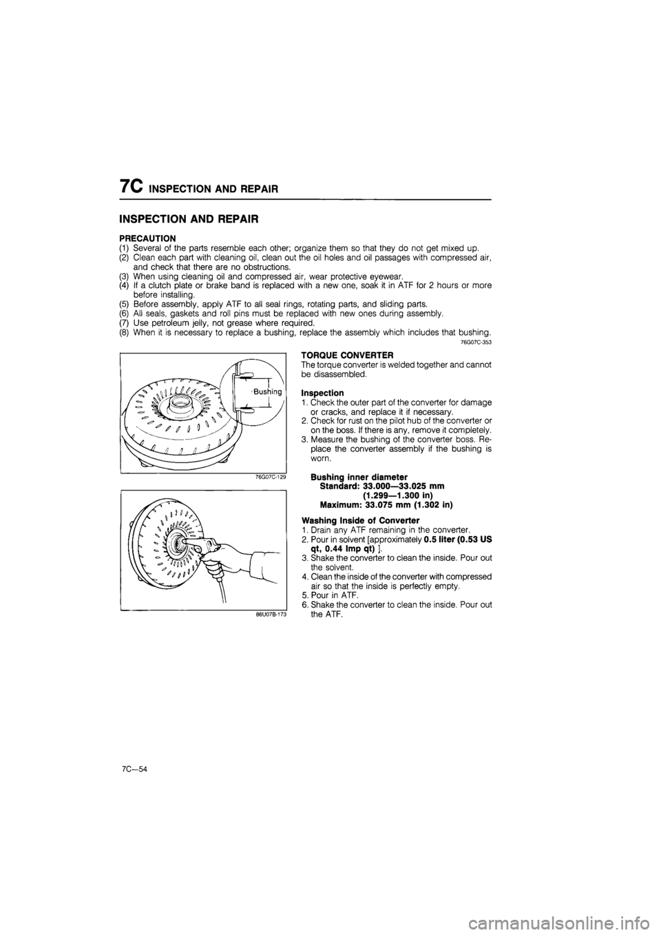
76G07C-353
TORQUE CONVERTER
The torque converter is welded together and cannot
be disassembled.
Inspection
1. Check the outer part of the converter for damage
or cracks, and replace it if necessary.
2. Check for rust on the pilot hub of the converter or
on the boss. If there is any, remove it completely.
3. Measure the bushing of the converter boss. Re-
place the converter assembly if the bushing is
worn.
Bushing inner diameter
Standard: 33.000—33.025 mm
(1.299—1.300 in)
Maximum: 33.075 mm (1.302 in)
Washing Inside of Converter
1. Drain any ATF remaining in the converter.
2. Pour in solvent [approximately 0.5 liter (0.53 US
qt, 0.44 Imp qt) ].
3. Shake the converter to clean the inside. Pour out
the solvent.
4. Clean the inside of the converter with compressed
air so that the inside is perfectly empty.
5. Pour in ATF.
6. Shake the converter to clean the inside. Pour out
the ATF.
7C-54
Page 1169 of 1865
INSPECTION AND REPAIR 7C
OIL PUMP
Disassembly
Disassemble in the sequence shown in the figure, referring to the disassembly note for specially marked
parts.
76G07C-130 1. Seal ring
2. Seal ring
3. Pump cover
4. Pump flange
5. Inner gear
6. Outer gear
7. Pump housing
63U07B-089
Disassembly note
Inner gear and outer gear
Mark the inner and outer gears with paint before
removing them.
76G07C-131
Inspection
Check for the following and replace any faulty parts:
1. Damaged or worn inner or outer gear tooth
surfaces.
2. Broken or worn seal ring.
76G07C-132
7C—55
Page 1170 of 1865
7C INSPECTION AND REPAIR
3. Clearance
Measured location Standard Maximum
1 Gear to pump cover 0.02—0.04 mm (0.001—0.002 in) 0.08 mm (0.003 in)
2 Outer gear to crescent 0.14-0.21 mm (0.006-0.008 in) 0.25 mm (0.010 in)
3 Outer gear to housing 0.05—0.20 mm (0.002—0.008 in) 0.25 mm (0.010 in)
4 Oil seal ring to ring groove 0.04-0.16 mm (0.002-0.006 in) 0.40 mm (0.016 in)
76G07C-133
Pump
housing
Bushing.
Sleeve
Pump cover
4. Damaged or worn inner gear bushing of pump
housing sleeve.
Sleeve outer diameter:
37.900 mm (1.492 in) max.
Bushing inner diameter:
38.075 mm (1.499 in) max.
76G07C-134
7C-56
Page 1171 of 1865
INSPECTION AND REPAIR 7C
76G07C-135
76G07C-136
76G07C-137
Assembly
1. Assemble so that the marks on the inner and out-
er gears are at the pump cover side.
2. Install the pump flange.
3. Install the oil pump cover.
Tightening torque: 11—14 N-m
(110—140 cm-kg, 95—122 in-lb)
4. Install the seal rings.
Seal ring outer diameter
A: 44 mm (1.732 in)
B: 43 mm (1.693 in)
5. When the assembly is completed, install the oil
pump shaft and make sure the gears turn easily.
76G07C-138
7C—57
Page 1175 of 1865
INSPECTION AND REPAIR 7C
9. Check the front clutch operation.
(1) Set the clutch assembly onto the oil pump.
(2) Check the front clutch operation by applying
compressed air through the fluid passage
shown.
Air pressure:
392 kPa (4.0 kg/cm2, 57 psi) max.
Caution
Apply air for no more than 3 seconds.
76G07C-150
(3) Pour ATF into the front clutch until the clutch
piston is fully submerged.
76G07C-151
(4) Check that no bubbles come from between the
piston and drum seal while applying com-
pressed air through the fluid passage shown.
Air pressure:
392 kPa (4.0 kg/cm2, 57 psi) max.
Caution
Apply air for no more than 3 seconds.
76G07C-152
7C-61