Page 58 of 1865
1 A ON-VEHICLE MAINTENANCE (VALVE SEAL)
VALVE SEAL
Removal
1. Disconnect the negative battery cable.
2. Drain the engine coolant.
3. Remove in the sequence shown in the figure referring to the removal note for specially marked parts.
76G01A-114
11. Fuel hose (carb.)
12. Rear housing
13. Rocker arm and shaft assembly
14. Camshaft cap (12-valve)
15. Camshaft
16. Valve keeper
17. Upper valve spring seat
18. Valve spring
19. Lower valve spring seat
20. Valve seal
1. Air cleaner assembly (carb.)
2. Air intake pipe (Fl)
3. High-tension lead and spark plug
4. Upper timing belt cover
5. Timing belt
6. Cylinder head cover
7. Camshaft pulley
8. Front housing
9. Distributor
10. Upper radiator hose
1A—26
Page 59 of 1865
1 A ON-VEHICLE MAINTENANCE (VALVE SEAL)
12-valve
O ® ® ® ©
Removal note
Timing belt
Remove the timing belt. (Refer to page 1A—14.)
Rocker arm and shaft assembly
Loosen the rocker arm shaft bolts in two or three steps
in the order shown in the figure.
76G01A-037
8-valve
CD © CD
® © ® ©
12-valve Valve seal
1. Remove the rocker arms and springs from the
rocker arm shaft.
2. Install the camshaft caps and rocker arm shafts
onto the cylinder head.
3. Plug the oil drain hole with a rag to prevent the pos-
sibility of the valve keepers from falling into the oil
pan.
86U01X-045
1A—27
Page 64 of 1865

ON-VEHICLE MAINTENANCE (VALVE SEAL) 1 A
76G01A-044
86U01X-212
76G01A-045
(8-valve)
Install the rocker arm and shaft assemblies on the cyl-
inder head and tighten them in three steps in the or-
der shown in the figure.
Tightening torque:
18—26 N-m (1.8—2.7 m-kg, 13—20 ft-lb)
Front housing
1. Replace the oil seal in the front housing.
2. Apply engine oil to the oil seal lip.
3. Install the front housing along with a new gasket.
Tightening torque:
19—25 N-m (1.9—2.6 m-kg, 14—19 ft-lb)
Rear housing
Install the rear housing along with a new gasket.
Tightening torque:
19—25 N-m (1.9—2.6 m-kg, 14—19 ft-lb)
Camshaft pulley
1. Install the camshaft pulley so that the mating mark
is aligned with the camshaft dowel pin straight up.
Note
For FE engine, align "2" mark.
For F8, F6 engine, align "3" mark.
2. Tighten the lock bolt.
Tightening torque:
47—65 N-m (4.8—6.6 m-kg, 35—48 ft-lb)
Timing belt
Install the timing belt. (Refer to TIMING BELT of ON-
VEHICLE MAINTENANCE.)
86U01X-052
1A—32
Page 67 of 1865

REMOVAL 1A
1. Battery and battery carrier 13. Three-way solenoid 22. P/S oil pump
2. Air cleaner assembly assembly 23. Engine side cover
3. High-tension lead 14. Canister hose (Fl, Middle 24. Front wheel
4. Accelerator cable East) 25. Tie-rod end
5. Throttle cable (ATX) 15. Heater hose 26. Stabilizer control rod
6. Fuel hose 16. Transaxle harness 27. Lower arm bushing
7. Radiator hose 17. Speedometer cable 28. Driveshaft
8. ATF hose (ATX) 18. Clutch release cylinder 29. Change rod (MTX)
9. Radiator harness (MTX) 30. Extension bar (MTX)
10. Radiator and cooling fan 19. Control cable (ATX) 31. Exhaust pipe
11. Engine harness 20. Drive belt 32. Engine mount
12. Brake vacuum hose 21. A/C compressor and 33. Engine and transaxle
bracket 34. Transaxle
76G01A-046
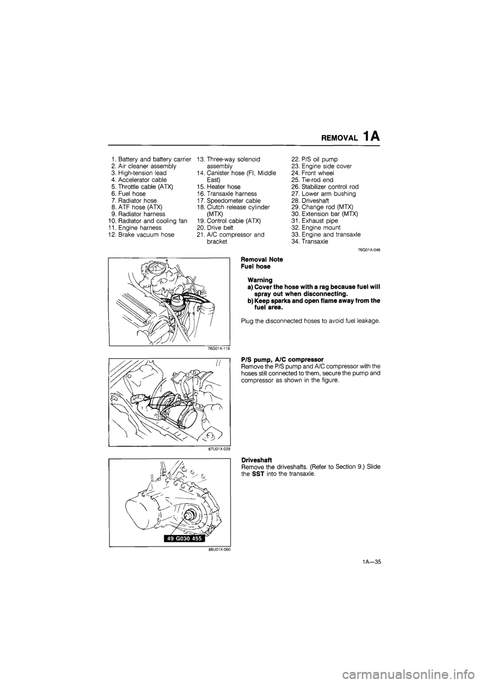
Removal Note
Fuel hose
Warning
a) Cover the hose with a rag because fuel will
spray out when disconnecting.
b) Keep sparks and open flame away from the
fuel area.
Plug the disconnected hoses to avoid fuel leakage.
76G01A-11E
P/S pump, A/C compressor
Remove the P/S pump and A/C compressor with the
hoses still connected to them, secure the pump and
compressor as shown in the figure.
67U01X-029
Driveshaft
Remove the driveshafts. (Refer to Section 9.) Slide
the SST into the transaxle.
86U01X-060
1A—35
Page 70 of 1865
1 A DISASSEMBLY (TIMING BELT)
TIMING BELT
69G01B-072
6. Timing belt idler pulley
7. Timing belt
8. Camshaft pulley
9. Timing belt pulley
1. Crankshaft pulley
2. Upper timing belt cover
3. Lower timing belt cover
4. Baffle plate
5. Timing belt tensioner and spring
1A—38
Page 71 of 1865
DISASSEMBLY (TIMING BELT) 1 A
Mark the
direction of
rotation
76G01A-121
76G01A-122
*
/ V \
T^pJl/1
Disassembly Note
Crankshaft pulley
1. Set the SST against the flywheel.
2. Remove the crankshaft pulley.
Timing belt
1. Loosen the tensioner lock bolt, and remove the ten-
sioner spring.
2. Mark the timing belt rotation for proper reinstalla-
tion if it is reused.
3. Remove the timing belt.
Caution
Be careful not to allow oil or grease on the
belt.
Camshaft pulley
Remove the pulley lock bolt using a screw driver to
prevent the camshaft from turning.
76G01A-123
1A—39
Page 92 of 1865

INSPECTION AND REPAIR 1 A
Crankpin
,/f
Main journal
76G01A-132
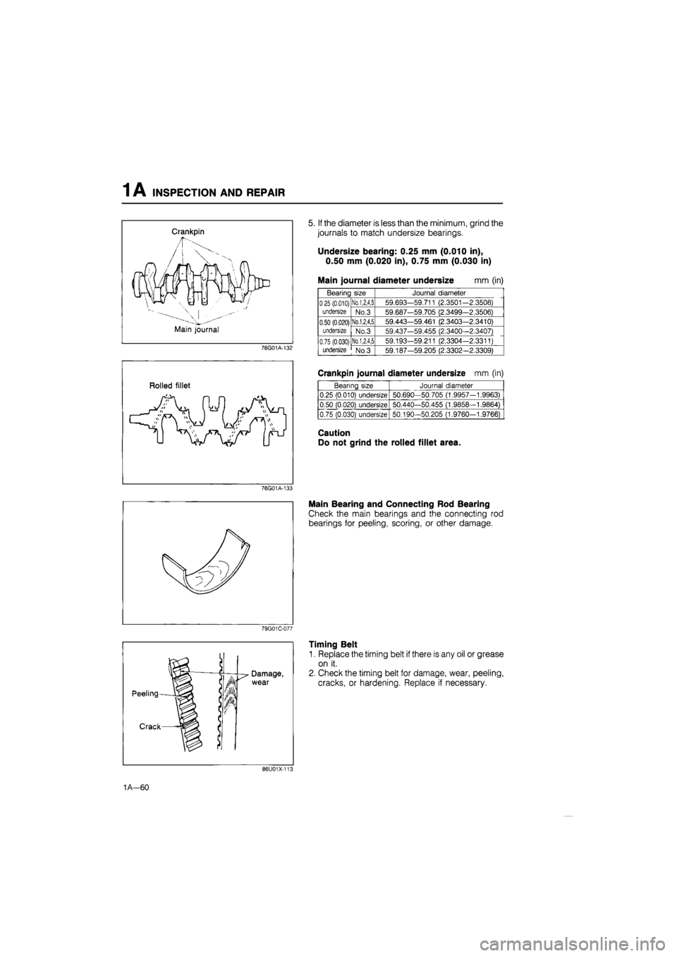
5. If the diameter is less than the minimum, grind the
journals to match undersize bearings.
Undersize bearing: 0.25 mm (0.010 in),
0.50 mm (0.020 in), 0.75 mm (0.030 in)
Main journal diameter undersize mm (in)
Bearing size Journal diameter
025 (0.010)
undersize
No.1,2,4,5 59.693-59.711 (2.3501-2.3508) 025 (0.010)
undersize No.3 59.687-59.705 (2.3499-2.3506)
0.50 (0.020)
undersize
No.1,2,4,5 59.443-59.461 (2.3403—2.3410) 0.50 (0.020)
undersize No.3 59.437-59.455 (2.3400—2.3407)
0.75 (0.030) undersize
No.1,2,4,5 59.193-59.211 (2.3304-2.3311) 0.75 (0.030) undersize No.3 59.187-59.205 (2.3302-2.3309)
Rolled fillet
Crankpin journal diameter undersize mm (in)
Bearing size Journal diameter
0.25 (0.010) undersize 50.690—50.705 (1.9957-1.9963)
0.50 (0.020) undersize 50.440-50.455 (1.9858—1.9864)
0.75 (0.030) undersize 50.190-50.205 (1.9760-1.9766)
Caution
Do not grind the rolled fillet area.
76G01A-133
Main Bearing and Connecting Rod Bearing
Check the main bearings and the connecting rod
bearings for peeling, scoring, or other damage.
79G01C-077
Timing Belt
1. Replace the timing belt if there is any oil or grease
on it.
2. Check the timing belt for damage, wear, peeling,
cracks, or hardening. Replace if necessary.
86U01X-117
1A—60
Page 93 of 1865
INSPECTION AND REPAIR 1 A
Caution
a) Never forcefully twist, turn inside out, or
bend the timing belt.
b) Be careful not to allow oil or grease on the
belt.
86U01X-114
Timing Belt Tensioner and Idler Pulley
Check the timing belt tensioner and idler pulley for
smooth rotation and abnormal- noise. Replace if
necessary.
Caution
Do not clean the tensioner with cleaning
fluids. If necessary, use a soft rag to wipe it
clean, and avoid scratching it.
86U01X-115
Timing Belt Tensioner Spring
Check the free length of the tensioner spring. Replace
if necessary.
Free length: 56.9 mm (2.240 in) FE
64.1 mm (2.524 in) F8, F6
76G01A-134
Timing Belt Pulley and Camshaft Pulley
Inspect the pulley teeth for wear, deformation, or other
damage. Replace if necessary.
Caution
Do not clean the pulley with cleaning fluids.
If necessary, use a rag to wipe it clean.
Timing Belt Cover (lower and upper)
Inspect the timing belt covers for damage or cracks.
Replace if necessary.
86U01X-117
1A—61