Page 771 of 1865
5 STARTER (DIESEL ENGINE, 2.0 KW TYPE)
(S) terminal Switch (K)
(B) terminal
Amp. meter
Voltmeter
4BG05X-105
No-load Test
1. After adjusting the pinion gap, form a test circuit
with a voltmeter and an ammeter.
Note
Use wires as thick as possible and tighten
each terminal fully.
2. Close switch "K" to run the starter.
If
the voltmeter
and ammeter show the following values while the
starter is running, it is normal.
Battery voltage: 11.5 volts
Current: 120 amperes or less
Gear shaft speed: at 4,000 or more
3. If any abnormality is noted, check it according to
"INSPECTION"
5—65
Page 777 of 1865

STARTER (DIESEL ENGINE, 2.2 KW TYPE) 5
4BG05X-113
4BG05X-080
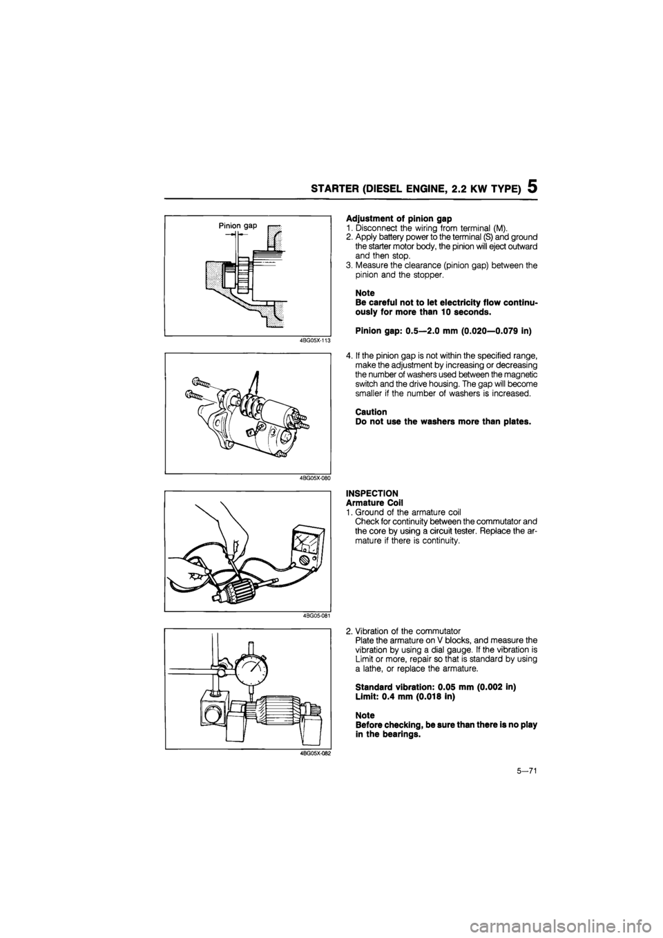
Adjustment of pinion gap
1. Disconnect the wiring from terminal (M).
2. Apply battery power to the terminal (S) and ground
the starter motor body, the pinion will eject outward
and then stop.
3. Measure the clearance (pinion gap) between the
pinion and the stopper.
Note
Be careful not to let electricity flow continu-
ously for more than 10 seconds.
Pinion gap: 0.5—2.0 mm (0.020—0.079 in)
4. If the pinion gap is not within the specified range,
make the adjustment by increasing or decreasing
the number of washers used between the magnetic
switch and the drive housing. The gap will become
smaller if the number of washers is increased.
Caution
Do not use the washers more than plates.
INSPECTION
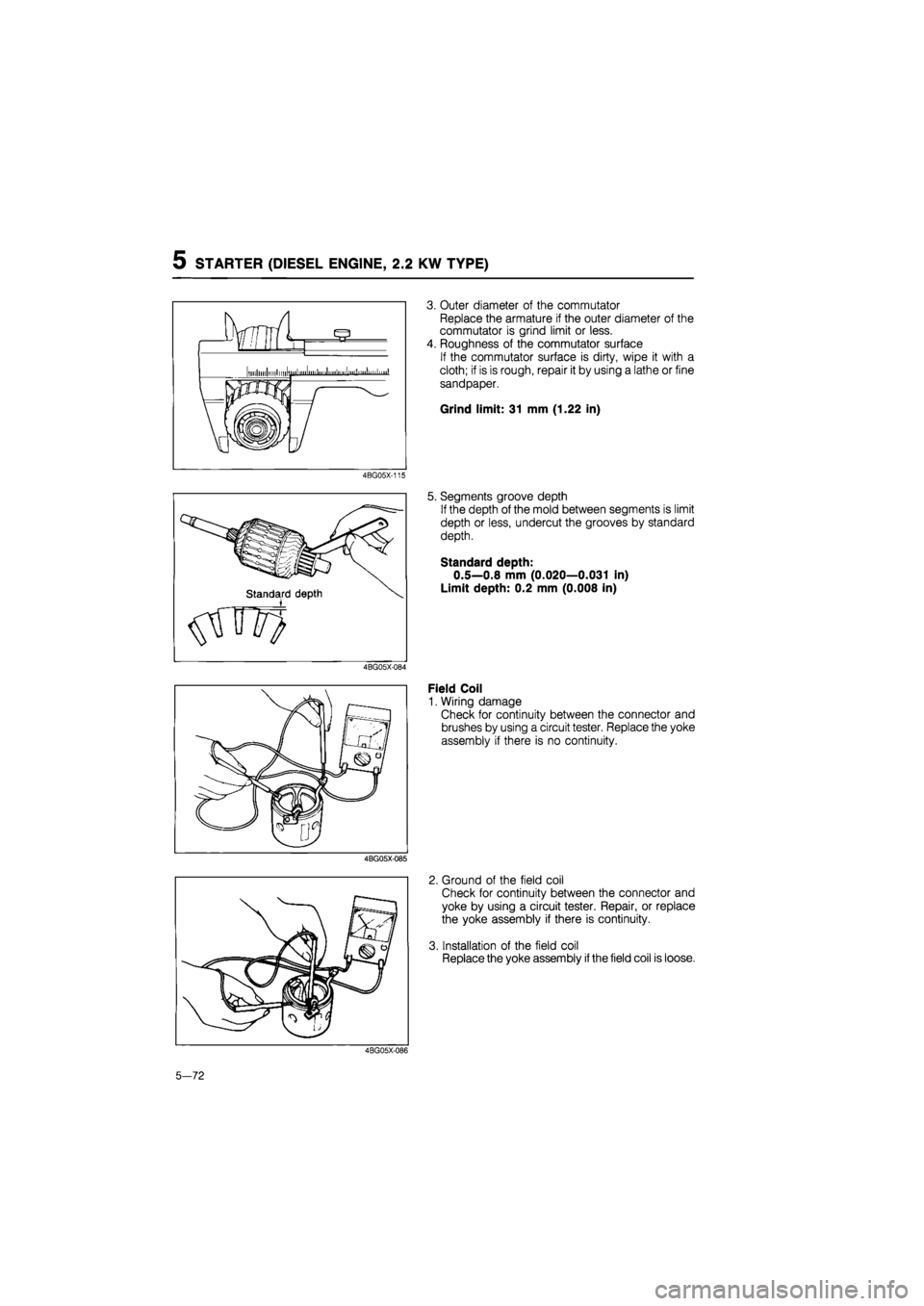
Armature Coil
1. Ground of the armature coil
Check for continuity between the commutator and
the core by using a circuit tester. Replace the ar-
mature if there is continuity.
4BG05-081
2. Vibration of the commutator
Plate the armature on V blocks, and measure the
vibration by using a dial gauge. If the vibration is
Limit or more, repair so that is standard by using
a lathe, or replace the armature.
Standard vibration: 0.05 mm (0.002 in)
Limit: 0.4 mm (0.018 in)
Note
Before checking, be sure than there is no play
in the bearings.
4BG05X-Q82
5-71
Page 778 of 1865

5 STARTER (DIESEL ENGINE, 2.2 KW TYPE)
4BG05X-115
4BG05X-085
3. Outer diameter of the commutator
Replace the armature if the outer diameter of the
commutator is grind limit or less.
4. Roughness of the commutator surface
If the commutator surface is dirty, wipe it with a
cloth; if is is rough, repair it by using a lathe or fine
sandpaper.
Grind limit: 31 mm (1.22 in)
5. Segments groove depth
If the depth of the mold between segments is limit
depth or less, undercut the grooves by standard
depth.
Standard depth:
0.5—0.8 mm (0.020—0.031 in)
Limit depth: 0.2 mm (0.008 in)
Field Coil
1. Wiring damage
Check for continuity between the connector and
brushes by using a circuit tester. Replace the yoke
assembly if there is no continuity.
2. Ground of the field coil
Check for continuity between the connector and
yoke by using a circuit tester. Repair, or replace
the yoke assembly if there is continuity.
3. Installation of the field coil
Replace the yoke assembly
if
the field coil is loose.
4BG05X-086
5-72
Page 779 of 1865
STATRER (DIESEL ENGINE, 2.2 KW TYPE) 5
11*mm S (0.433 in)
A
A 18 mm
(0,709)
Brush and Brush Holder
1. Brush
If the brushes are worn beyond the wear limit, or
if the wear is near the limit, replace the brushes.
Standard: 18 mm (0.709 in)
Wear limit: 11 mm (0.433 in)
76G05X-047
2. Brush spring
(1) Measure the force of the brush spring by us-
ing a spring balance.
(2) Replace the brush spring if the force is Limit
or less.
Limit: 9 N (900 g, 31.75 oz)
4BG05X-088
3. Brush holder
(1) Check for continuity between the insulated
brush and the plate by using a circuit tester.
(2) Repair or replace if there is continuity.
(3) Also check to be sure that the brush slides
smoothly inside the brush holder.
4BG05X-089
Magnetic Switch
1. Check continuity between (S) terminal and (M) ter-
minal, and between (S) terminal and ground (body).
2. If there is no continuity, the wire is broken so re-
place the magnetic switch.
4BG05X-116
5-73
Page 781 of 1865

5 STARTER (DIESEL ENGINE, 2.0 KW TYPE)
Hold-in Test
1. After completing the pull-in test, disconnect the wire
from terminal M (with the pinion left ejected).
2. The hold-in coil is functioning properly if the pin-
ion does not return.
4BG05X-093
Return Test
1. Connect the battery between terminal M of the
magnetic switch and the body, as shown in the
figure.
2. Pull the pinion out manually to the pinion stopper
position.
3. The pinion should immediately return to its origi-
nal position when it is released.
4BG05X-094
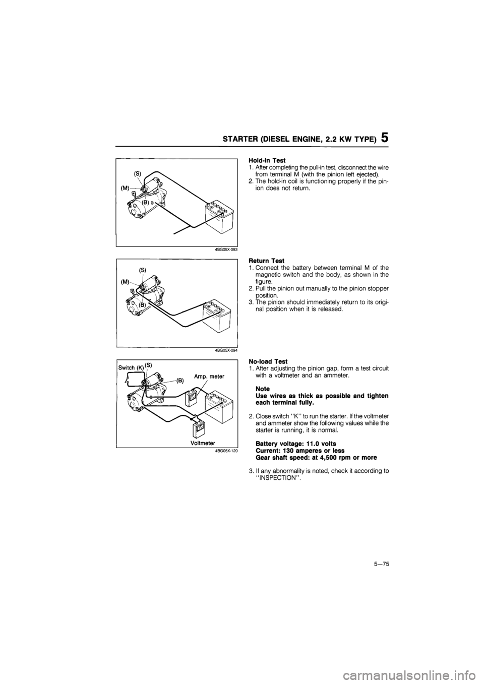
No-load Test
1. After adjusting the pinion gap, form a test circuit
with a voltmeter and an ammeter.
Note
Use wires as thick as possible and tighten
each terminal fully.
2. Close switch "K" to run the starter.
If
the voltmeter
and ammeter show the following values while the
starter is running, it is normal.
Battery voltage: 11.0 volts
Current: 130 amperes or less
Gear shaft speed: at 4,500 rpm or more
3. If any abnormality is noted, check it according to
"INSPECTION".
5—75
Page 784 of 1865

QUICK START SYSTEM (QSS) 5
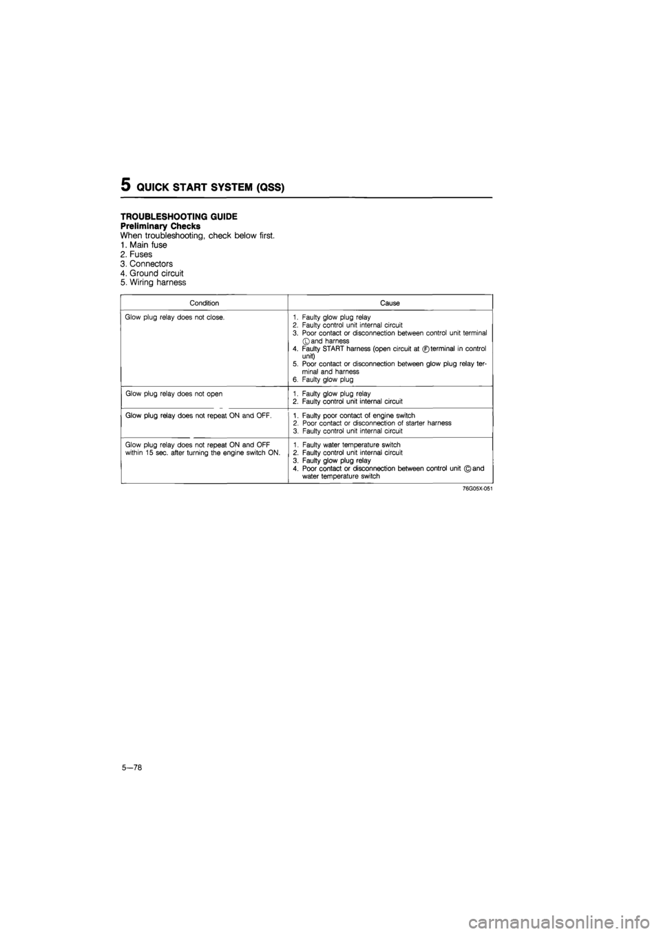
TROUBLESHOOTING GUIDE
Preliminary Checks
When troubleshooting, check below first.
1. Main fuse
2. Fuses
3. Connectors
4. Ground circuit
5. Wiring harness
Condition Cause
Glow plug relay does not close. 1. Faulty glow plug relay 2. Faulty control unit internal circuit
3. Poor contact or disconnection between control unit terminal ©and harness
4. Faulty START harness (open circuit at ©terminal in control unit) 5. Poor contact or disconnection between glow plug relay ter-minal and harness 6. Faulty glow plug
Glow plug relay does not open 1. Faulty glow plug relay 2. Faulty control unit internal circuit
Glow plug relay does not repeat ON and OFF. 1. Faulty poor contact of engine switch 2. Poor contact or disconnection of starter harness 3. Faulty control unit internal circuit
Glow plug relay does not repeat ON and OFF within 15 sec. after turning the engine switch ON. 1. Faulty water temperature switch 2. Faulty control unit internal circuit
3. Faulty glow plug relay
4. Poor contact or disconnection between control unit © and water temperature switch
76G05X-051
5-78
Page 785 of 1865

QUICK START SYSTEM (QSS) 5
CONTROL UNIT
Inspection
1. Connect a voltmeter to the control unit as shown
in the figure.
2. Check the voltage of the terminal.
3. Replace the control unit if necessary.
Caution
If the proper voltage is not indicated on the
voltmeter, check all wiring connections and
finally, check that component.
63G05X-337
Control Unit Connector
Terminal Input Output Connection to Operation condition Voltage Remark
for 6 sec. approx. 12V
L (GW) O Glow plug relay Engine switch: ON (No cranking) after 6 sec.
OV 12V Coolant temperature; below 30°C (86°F) after 6 sec.
OV Coolant temperature; above 30°C (86°F)
H
(B) — — Ground OV
E (BW) 0 Engine switch (ON) Engine switch: ON approx. 12V
F
(BR) O Engine switch (START) Engine switch: START approx. 12V
C o
Water
temperature switch
Engine switch: ON (No cranking)
approx. 12V Coolant temperature; below 30°C (86°F)
(BrB) o
Water
temperature switch
Engine switch: ON (No cranking)
approx. OV Coolant temperature;
above 30°C (86°F)
At cranking OV <- 12V
B 0 Glow plug
For 15 sec. after engine has started OV <-> 12V Coolant temperature;
(Gr) 0 Glow plug After 15 sec. OV below 30°C (86 °F)
After engine has started OV Coolant temperature; above 30°C (86°F)
K o Indicator Engine switch: ON
For 3 sec. OV
(WR) o Indicator Engine switch: ON after 3 sec. approx. 12V
76G05X-052
u® x y i © © X 1
© © X ®
5-79
Page 892 of 1865

7B TROUBLESHOOTING (G4A-EL)
Item Indication Condition
OUTPUT (Digital display)
1
1
st gear position
GEAR* 2 2nd gear position GEAR*
3 3rd gear position
4 Overdrive (OD) gear position
86U07B-033
Note
a) The back-up condition is as following condition
S range, hold mode, and the accelerator pedal depressed fully.
b)The * marked items should be checked during the engine running or driving.
Comprehensive Usage
The EC-AT Tester can be used to inspect slippage of friction elements, shift points, and shift sequence
during the road test.
The inspection procedure is shown in STEP 7 (ROAD TEST).
Solenoid valve operation table
RANGE GEAR SOLENOID VALVES RANGE GEAR 1-2 2-3 3-4 Lock-up
P Non ON
R Reverse ON
N Below aDDrox. 18 km/h (11 mDh) ON N Above approx. 18 km/h (11 mph) ON
1st ON ON
2nd ON ON ON
Below approx. 40 km/h (25 mph)
D 3rd Above approx. 40 km/h (25 mph)
Lock-uo OFF ON Above approx. 40 km/h (25 mph) Lock-up ON ON ON
OD Lock-up OFF ON ON OD Lock-uo ON ON ON ON
1st ON ON
S 2nd ON ON ON S
3rd Below approx. 40 km/h (25 mph) 3rd Above approx. 40 km/h (25 mph) ON
1st ON ON
L 2nd Below approx. 110 km/h (68 mph) ON ON 2nd Above approx. 110 km/h (68 moh) ON
2nd ON ON ON
D 3rd Below approx. 40 km/h (25 moh) 3rd Above approx. 40 km/h (25 moh) ON
2nd ON ON
HOLD S 3rd Below approx. 40 km/h (25 mph) 3rd Above approx. 40 km/h (25 mph) ON
1st ON
L 2nd Below approx. 110 km/h (68 mph) ON ON 2nd Above approx. 110 km/h (68 mph) ON
7B—26