Page 397 of 1865

4A FUEL SYSTEM
76G04A-037
Float Level
Caution
This adjustment must be made without the
gasket on the air horn.
1. Turn the air horn upside-down and allow the float
to lower by its own weight.
2. Measure clearance H between the float and the
air horn.
Clearance H: 12.5 mm (0.49 in)
3. If not as specified, bend the float seat lip A to adjust.
4. Turn the air horn to the normal position and allow
the float to lower by its own weight.
5. Measure clearance L between the bottom of the
float and the air horn.
Clearance L: 44 mm (1.73 in)
6. If not as specified, bend the float stop B to adjust.
76G04A-038
76G04A-039
Fast Opening
F6 and FE 8Valve (Except General)
1. With the choke valve fully closed, measure the
clearance between the primary throttle valve and
the wall of the throttle bore.
Specification:
Engine Spec. Clearance mm (in)
F6 General and
Singapore 1.40—1.76
(0.055-0.069) FE 8Valve Middle East and
Unleaded Fuel
1.40—1.76
(0.055-0.069)
2. If not within specification, carefully bend the con-
necting rod to adjust.
4A—32
Page 704 of 1865

FUEL SYSTEM 4D
76G04D-077
76G04D-078
^^^
76G04D-079
Red paint
Injection Nozzle Disassembly
Disassemble the injection nozzle.
1. Nozzle holder
2. Adjusting shim
3. Pressure spring
4. Pressure pin
5. Distance piece
6. Nozzle
7. Retaining ring
Cleaning
Clean the parts in clean test oil.
Injection Nozzle Inspection
1. Check the needle valve, nozzle body, and other
parts for damage.
2. Hold the nozzle body upright and insert approxi-
mately two thirds of the needle valve, and check
that the needle valve drops to the valve seat by
its own weight.
Injection Nozzle Assembly
1. Assemble the injection nozzle.
Tightening torque of nozzle body:
29—49 N-m (3.0—5.0 m-kg, 22—36 ft-lb)
2. Check the injection starting pressure, and atomi-
zation. (Refer to page 4D—32.)
Injection Nozzle Installation
1. Install in the reverse order of removal, referring to
the installation note.
2. Check for fuel leakage.
Installation note
Nozzle gasket
Install a new gasket with the red face toward the
nozzle.
76G04D-080
4D-33
Page 718 of 1865
DISTRIBUTOR
8.
If
the mark is not aligned, loosen the distributor lock
bolt, and turn the distributor housing to make the
adjustment.
9. Reconnect the vacuum hoses, or disconnect the
jumper wire from the test connector.
10. Tighten the distributor lock bolt to specified torque.
Tightening torque:
18.6—25.5 Nm
(1.9—2.6 m-kg, 13.7—18.8 ft-lb)
86U05X-051
SPARK CONTROL (Except FE DOHC)
Centrifugal Advance
1. Warm up the engine to the normal operating tem-
perature.
2. Check that the idle speed and initial ignition tim-
ing are correct.
3. Disconnect the vacuum hoses from the vacuum
control unit and plug them.
76G05X-009
F6
Engine Speed (rpm)
4. While gradually increasing the engine speed, use
a timing light to check the advance on the pulley.
Excess advance weak governor spring
(If the governor spring is broken,
the advance will rise very high)
Insufficient advance...governor weight or cam
malfunction
86U05X-053
F8
Engine Speed (rpm) Engine Speed (rpm)
5-12
Page 1496 of 1865

WHEELS AND TIRES 1 2
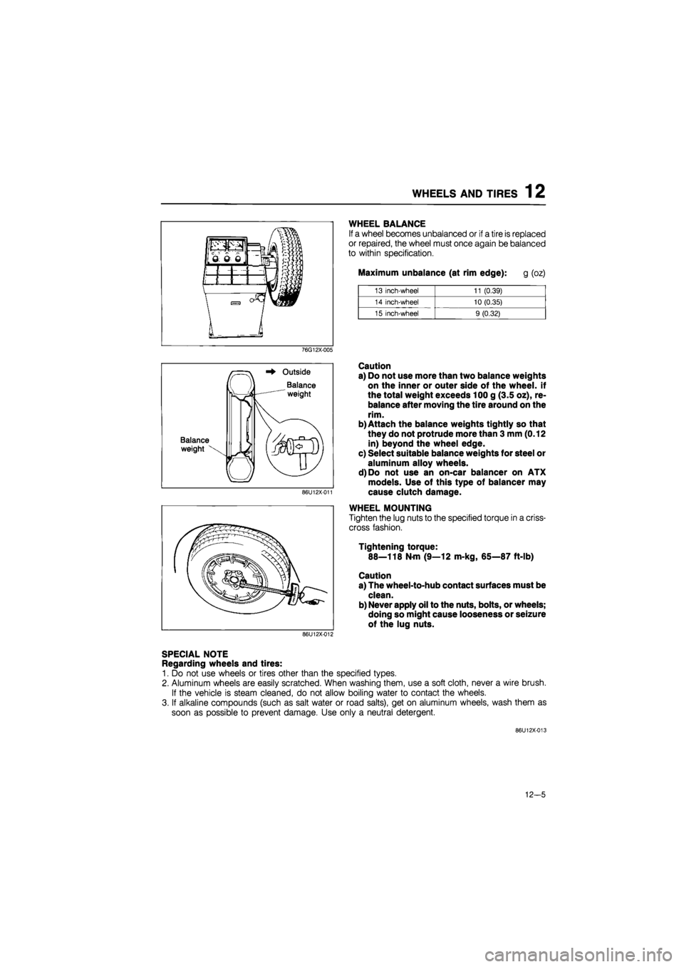
WHEEL BALANCE
If a wheel becomes unbalanced or if a tire is replaced
or repaired, the wheel must once again be balanced
to within specification.
Maximum unbalance (at rim edge): g (oz)
13 inch-wheel 11 (0.39)
14 inch-wheel 10 (0.35)
15 inch-wheel 9 (0.32)
76G12X-005
Balance
weight
Outside
Balance
weight
86U12X-011
Caution
a) Do not use more than two balance weights
on the inner or outer side of the wheel, if
the total weight exceeds 100 g (3.5 oz), re-
balance after moving the tire around on the
rim.
b) Attach the balance weights tightly so that
they do not protrude more than 3 mm (0.12
in) beyond the wheel edge.
c) Select suitable balance weights for steel or
aluminum alloy wheels.
d)Do not use an on-car balancer on ATX
models. Use of this type of balancer may
cause clutch damage.
WHEEL MOUNTING
Tighten the lug nuts to the specified torque in a criss-
cross fashion.
Tightening torque:
88—118 N-m (9—12 m-kg, 65—87 ft-lb)
Caution
a) The wheel-to-hub contact surfaces must be
clean.
b) Never apply oil to the nuts, bolts, or wheels;
doing so might cause looseness or seizure
of the lug nuts.
86U12X-012
SPECIAL NOTE
Regarding wheels and tires:
1. Do not use wheels or tires other than the specified types.
2. Aluminum wheels are easily scratched. When washing them, use a soft cloth, never a wire brush.
If the vehicle is steam cleaned, do not allow boiling water to contact the wheels.
3. If alkaline compounds (such as salt water or road salts), get on aluminum wheels, wash them as
soon as possible to prevent damage. Use only a neutral detergent.
86U12X-013
12-5
Page 1660 of 1865
INTRODUCTION 15
69G15X-006
4BG15X-003
69G15X-007
/Wire
Shield braid wire
Insulation
Replacement of Fuse
1. When replacing a fuse, be sure to replace it with
one of the specified capacity.
If, after a fuse has been replaced, it fails again, there
is probably a short in the circuit, and the wiring
should be checked.
2. Be sure the negative battery terminal is disconnect-
ed before replacing a main fuse.
3. When replacing a fuse, use the supplied fuse puller
in the fuse box cover.
Thin Insulation Wire
To reduce the weight of the wiring harness, a thin
coating of high resistance insulation material is used.
Shielded braid wire
This wire is used to prevent a malfunction in impor-
tant circuits that are susceptible to outside signals or
interference.
Eg.
Ignition coil
02 sensor
69G15X-008
15—5
Page 1832 of 1865

30 TECHNICAL DATA
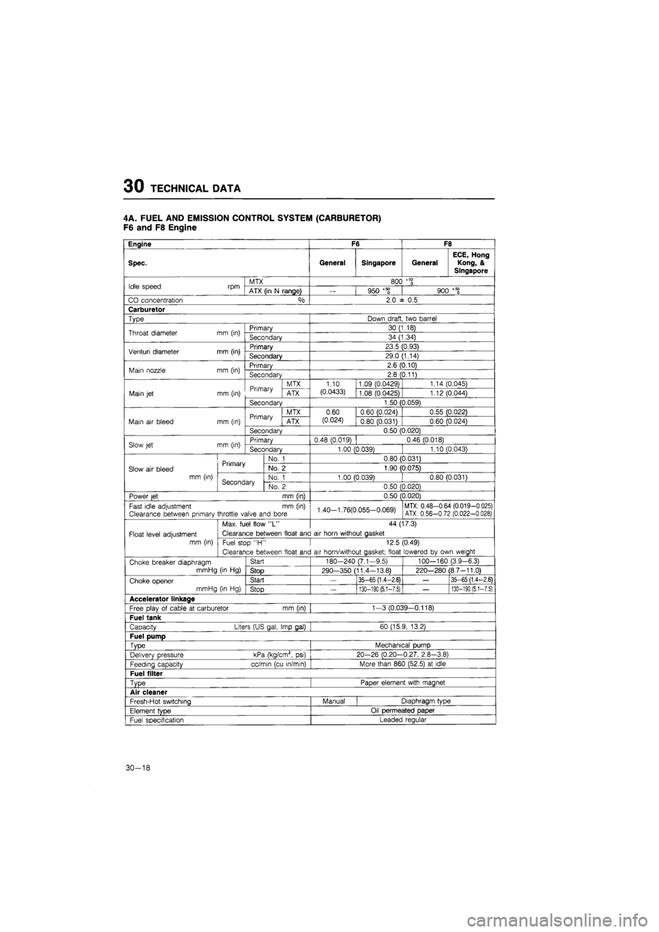
4A. FUEL AND EMISSION CONTROL SYSTEM (CARBURETOR)
F6 and F8 Engine
Engine F6 F8
Spec. General Singapore General
ECE, Hong
Kong, &
Singapore
Idle speed rpm MTX 800
+ 50
0 Idle speed rpm ATX (in
N
range)
—
950 +58 900
+ 50
0
CO concentration °/o 2.0
± 0.5
Carburetor
Type Down draft two barrel
Throat diameter mm (in) Primary 30 (1.18) Throat diameter mm (in) Secondary 34 (1.34)
Venturi diameter mm (in) Primary 23.5 (0.93) Venturi diameter mm (in) Secondary 29.0 (1.14)
Main nozzle mm (in) Primary 2.6 (0.10) Main nozzle mm (in) Secondary 2.8 (0.11)
Primary MTX 1.10 1.09 (0.0429) 1.14 (0.045)
Main
jet
mm (in) Primary ATX (0.0433) 1.08 (0.0425) 1.12 (0.044)
Secondary 1.50 (0.059)
Primary MTX 0.60 0.60 (0.024) 0.55 (0.022)
Main
air
bleed mm (in) Primary ATX (0.024) 0.80 (0.031) 0.60 (0.024)
Secondary 0.50 (0.020)
Slow
jet
mm (in) Primary 0.48 (0.019) 0.46 (0.018) Slow
jet
mm (in) Secondary 1.00 (0.039) 1.10 (0.043)
Primary No.
1
0.80 (0.031)
Slow
air
bleed Primary No.
2
1.90 (0.075)
mm (in) Secondary No.
1
1.00 (0.039) 0.80 (0.031) Secondary No.
2
0.50 (0.020)
Power
jet
mm (in) 0.50 (0.020)
Fast idle adjustment
mm (in)
Clearance between primary throttle valve and bore 1.40-1.76(0.055-0.069) MTX: 0.48-0.64 (0.019-0 025) ATX: 0.56-0.72 (0.022-0.028)
Max. fuel flow
"L"
44 (17.3)
Float level adjustment Clearance between float and
air
horn without gasket
mm (in) Fuel stop
"H •
12.5 (0.49)
Clearance between float and
air
horn/without gasket; float lowered
by
own weight
Choke breaker diaphragm Start 180-240 (7.1-9.5) 100—160 (3.9-6.3)
mmHg
(in Hg)
Stop 290—350 (11.4-13.8) 220-280 (8.7-11.0)
Choke opener Start
—
35-65 (1.4-2.6)
—
35-65 (1.4-2.6)
mmHg
(in Hg)
Stop
—
130-190 (5.1-7.5)
—
130-190
(5,1-7.5)
Accelerator linkage
Free plav
of
cable
at
carburetor mm (in) 1-3 (0.039—0.118)
Fuel tank
Capacity Liters (US gal, Imp gal) 60 (15.9, 13.2)
Fuel pump
Type Mechanical pump
Delivery pressure kPa (kg/cm2,
psi)
20-26 (0.20-0.27, 2.8-3.8)
Feedina capacity cc/min (cu in/min) More than 860 (52.5)
at
idle
Fuel filter
Type Paper element with magnet
Air cleaner
Fresh-Hot switching Manual Diaphragm type
Element
tvDe
Oil permeated paper
Fuel specification Leaded regular
30-18