Page 29 of 1865

Interval
Procedure & item
Number of Months or km, whichever corns first
©1 ©2 ©3 ©4 Service data and inspection point Page
Interval
Procedure & item
Months — 6 12 18 24 30 36 42 48 ©1 ©2 ©3 ©4 Service data and inspection point Page
Interval
Procedure & item
x
1000
Km
1 10 20 30 40 50 60 70 80 ©1 ©2 ©3 ©4 Service data and inspection point Page
Interval
Procedure & item
Miles x
1000 0.6 6 12 18 24 30 36 42 48
©1 ©2 ©3 ©4 Service data and inspection point Page
Choke system I I I I O O X X
• Carburetor linkage • Choke diaphragm • Choke valve clearance • Unloader system
4A—26
4A-34
4A-34
4A—33
Cooling system I I I I O O o o • Hoses for cracks or wear 3A-5 3B—4
Engine coolant (with reservoir) Reprace every 24 months O O o o • Coolant level 3 A—5 3B—4
Battery electrolyte level and specific gravity I I I I O o o o • Electrolyte level • Specific gravity 5—8
Engine timing belts *2 Replace every 100,000 km O o o o —
1A—14 1B—11 1C—11
Drive belts *4 A I I I I I I I I O o o o • Cracks or damage • Tension
1A—7
1
B—6 1C—7
Engine valve clearance
(1) For Gasoline engine (I) I (I) I (I) I (I) I
T
O o X o
• Valve clearance F6, F8, FE-8-valve (Hot engine) IN: 0.30 mm (0.012 in) EX: 0.30 mm (0.012 in) FE-12-valve, FE (DOHC) IN: 0; Maintenance free EX: 0; Maintenance free RF-N (Cold engine) IN: 0.25 mm (0.01 in) EX: 0.35 mm (0.014 in)
1A—10
1C—85
Exhaust manifold nuts and bolts T T
I
T o o X X
• Retighten the intake and exhaust manifold nuts
N-m (m-kg, ft-lb) 1A—86 1B—68 1C—89 Exhaust manifold nuts and bolts T T
I
T o o X X IN EX 1A—86 1B—68 1C—89 Exhaust manifold nuts and bolts T T
I
T o o X X
F6, F8, FE 19-30 (1.9-3.1, 14-22) 22-28 (2.2-2.9, 16-21)
1A—86 1B—68 1C—89 Exhaust manifold nuts and bolts T T
I
T o o X X
RF-N 16-23 (1.6-2.3,
12-17) 22-26 (2.2-2 7,
16-20)
1A—86 1B—68 1C—89
Engine oil *1 Replace every 5000 km or 6 months X X o o
• Oil pan capacity FE DOHC: 3.6 liters
(3.8 US qt, 3.2 Imp qt) RF-N: 5.0 liters
(5.3 US pt, 4.4 Imp qt)
2A-6
2B—6
m >
o m
H >
00 r~ m
a
2
Page 30 of 1865

Interval
Procedure & item
Number of Months or km, whichever corns first
Months
x 1000 Km
Miles x 1000
Engine oil
Oil filter
Fuel filter (R) only for carbretor
Fuel lines and hoses (I) only for Diesel
Spark plugs
Initial ignition timing
Idle speed (I) only for carbretor
0.6
(I)
6
10
(0
12
20
12
(R)
18
30
18
(I)
24
40
24
30
50
30
(I)
36
60
36
(R)
42
70
42
(I)
48
80
48
®1
O
o
o
o
o
o
o
©2
O
o
o
o
o
o
o
©3
O
o
o
o
o
o
©4
O
o
o
Service data and inspection point
Oil pan capacity F6, F8, FE 3.6 liters (3.8 US qt, 3.2 Imp qt)
Oil filter capacity F8, FE 12-valve (SOHC)
0.3 liters (0.32 US qt, 0.26 Imp qt)
FE (DOHC) 0.2 liters (0.21 US qt, 0.18 Imp qt) RF-N
0.4 liters (0.42 US qt, 0.35 Imp qt)
Fittings, connections and compo-
nents for leaks
Plug gap FE DOHC 0.7—0.8 mm (0.028-0.031 in) Others 0.75—0.85 mm (0.030—0.033 in) Recommended spark plugs
F6,F8,FE FE
12 VALVE,
DOHC
NGK BPR 5ES BPR 6ES BCPR 5E
BCPR 6E
Nippon
Denso W16EXR-U
W20EXR-U
Q16PR-U* Q20PR-U
Initial ignition timing F6 F8 FE (8 VALVE) (12 VALVE)
6 ±
1
° BTDC FE (DOHC) 12 ± 1° BTDC
Check the idle speed
MTX 80015? rpm
ATX F6 900 rpm (in "N" range) ATX F8, FE 900 t5? rpm (in "N" range)
FE DOHC 700—800 rpm
§ *Only FE 12 VALVE
Page
2A—6
2A-6
2B-6
4D—21
5-9
5-11
4A—38
4C-29
m z >
z o m
H >
CD I-m
T1
o
o
(A O X m o c i-m o
m z >
z o m
Page 33 of 1865
ENGINE
(SOHC)
OUTLINE 1A— 2
STRUCTURAL VIEW 1A— 2
SPECIFICATIONS 1A— 4
TROUBLESHOOTING GUIDE 1A— 4
TUNE-UP PROCEDURE 1A— 6
ON-VEHICLE INSPECTION 1A-13
COMPRESSION 1A—13
ON-VEHICLE MAINTENANCE 1A—14
TIMING BELT 1A—14
CYLINDER HEAD 1A—20
VALVE SEAL 1A—26
REMOVAL 1A—34
DISASSEMBLY 1A—36
AUXILIARY PARTS 1A—36
TIMING BELT 1A—38
CYLINDER HEAD 1A—40
CYLINDER BLOCK 1A—44
INSPECTION AND REPAIR 1A—48
ASSEMBLY 1A—62
CYLINDER BLOCK 1A—62
CYLINDER HEAD 1A—73
TIMING BELT 1A—82
AUXILIARY PARTS 1A—86
INSTALLATION 1A—91
TRANSAXLE ASSEMBLY 1A—91
ENGINE INSTALLATION 1A—92
76G01A-001
Page 36 of 1865
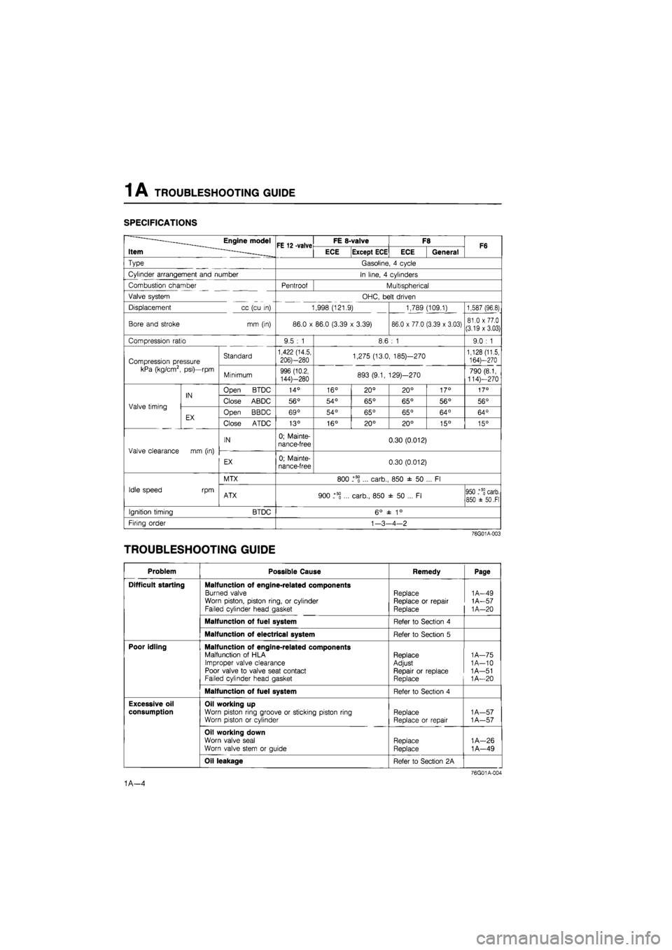
1A TROUBLESHOOTING GUIDE
SPECIFICATIONS
——Engine model
Item ^ FE 12 -valve FE 8-valve F8 F6 ——Engine model
Item ^ FE 12 -valve ECE Except ECE ECE General F6
Type Gasoline, 4 cycle
Cylinder arrangement and number In line, 4 cylinders
Combustion chamber Pentroof Multispherical
Valve system OHC, belt driven
Displacement cc (cu in) 1,998 (121.9) 1,789 (109.1) 1,587 (96.8)
Bore and stroke mm (in) 86.0 x 86.0 (3.39 x 3.39) 86.0 x 77.0 (3.39 x 3.03) 81.0 x 77.0 (3.19 x 3.03)
Compression ratio 9.5 : 1 8.6 : 1 9.0 : 1
Compression pressure kPa (kg/cm2, psi)—rpm
Standard 1,422 (14.5,
206)—280 1,275 (13.0, 185)—270 1,128 (11.5, 164)—270 Compression pressure kPa (kg/cm2, psi)—rpm Minimum 996 (10.2,
144)—280 893 (9.1, 129)—270 790 (8.1, 114)—270
Valve timing
IN Open BTDC 14° 16° 20° 20° 17° 17°
Valve timing
IN Close ABDC 56° 54° 65° 65° 56° 56° Valve timing
EX Open BBDC 69° 54° 65° 65° 64° 64° Valve timing
EX Close ATDC 13° 16° 20° 20° 15° 15°
Valve clearance mm (in)
IN 0; Mainte-nance-free 0.30 (0.012)
Valve clearance mm (in)
EX 0; Mainte-nance-free 0.30 (0.012)
Idle speed rpm
MTX 800 _+5S ... carb., 850 ± 50 ... Fl
Idle speed rpm ATX 900 _+5g ... carb., 850 ± 50 ... Fl 950 _+5§ carb. 850 ±
50
.Fl
Ignition timing BTDC 6° ± 1°
Firing order
1
-3-4-2
76G01A-003
TROUBLESHOOTING GUIDE
Problem Possible Cause Remedy Page
Difficult starting Malfunction of engine-related components
Burned valve Worn piston, piston ring, or cylinder Failed cylinder head gasket
Replace Replace or repair Replace
1A-49
1A-57
1
A—20
Malfunction of fuel system Refer to Section 4
Malfunction of electrical system Refer to Section 5
Poor idling Malfunction of engine-related components Malfunction of HLA Improper valve clearance Poor valve to valve seat contact Failed cylinder head gasket
Replace Adjust Repair or replace Replace
1
A—75 1A-10 1 A—51
1
A—20
Malfunction of fuel system Refer to Section 4
Excessive oil
consumption
Oil working up Worn piston ring groove or sticking piston ring Worn piston or cylinder Replace Replace or repair
1
A—57 1A—57
Oil working down
Worn valve seal
Worn valve stem or guide Replace
Replace
1A—26
1A—49
Oil leakage Refer to Section 2A
76G01A-004
1A—4
Page 37 of 1865

TROUBLESHOOTING GUIDE 1 A
Problem Possible Cause Remedy Page
Insufficient power Insufficient compression Malfunction of HLA Improper valve clearance Compression leakage from valve seat Seized valve stem Weak or broken valve spring Failed cylinder head gasket Cracked or distorted cylinder head Sticking, damaged, or worn piston ring Cracked or worn piston
Replace
Adjust
Repair
Replace Replace Replace Replace Replace Replace
1A—75 1A—10
1
A—51 1A—49 1A—53
1
A—20 1A—48 1A—57
1
A—57
Malfunction of fuel system Refer to Section 4
Others Slipping clutch Dragging brakes Wrong size tires
Refer to Section 6 Refer to Section 11 Refer to Section 12
Abnormal
combustion
Malfunction of engine-related components Malfunction of HLA
Improper valve clearance Sticking or burned valve
Weak or broken valve spring Carbon accumulation in combustion chamber
Replace Adjust Replace Replace
Eliminate carbon
1
A—75 1A—10 1A—49 1A—53
Malfunction of fuel system Refer to Section 4
Engine noise Crankshaft or bearing related parts
Excessive main bearing oil clearance Main bearing seized or heat-damaged Excessive crankshaft end play Excessive connecting rod bearing oil clearance Connecting rod bearing seized or heat-damaged
Replace or repair Replace
Replace or repair Replace or repair Replace
1A—65
1
A—65 1A—66 1A—67
1
A—67
Piston related parts Worn cylinder Worn piston or piston pin Seized piston Damaged piston ring Bent connecting rod
Replace or repair
Replace
Replace Replace Replace
1A—55
1
A—57
1
A—57
1
A—57 1A—59
Valves or timing related parts Malfunction of HLA* Improper valve clearance Broken valve spring Excessive valve guide clearance Malfunction of timing belt tensioner
Replace Adjust
Replace Replace Replace
1A—75 1A—10 1A—53 1A—49 1A—61
Malfunction of cooling system Refer to Section 3A
Malfunction of fuel system Refer to Section 4
Others Malfunction of water pump bearing Improper drive belt tension Malfunction of alternator bearing Exhaust gas leakage
Replace Adjust Replace Repair
1 A— 7
1
A—48
* Tappet noise may occur if the engine is not operated for an extended period of time. The noise should stop after the
engine has reached normal operating temperature.
76G01A-005
1A—5
Page 42 of 1865

1A TUNE-UP PROCEDURE
No.1 IN No.2 IN
No.1 EX No.3 EX
76G01A-015
Adjust bolt
^N^^^^^Lock nut
SsKs&b ' Valve
Camshaft >Nw clearance
76G01A-016
76G01A-017
Valve Clearance (8-valve)
1. Warm up the engine to the normal operating tem-
perature.
2. With the piston of the No.1 cylinder at TDC of com-
pression stroke.
Adjust the valve clearance as shown in the figure.
Valve clearance (valve side)
IN : 0.30 mm (0.012 in)
EX: 0.30 mm (0.012 in)
3. Turn the crankshaft one full turn so that the piston
of the No.4 cylinder is at TDC of compression
stroke.
Adjust the clearances of the remaining valves.
Ignition Timing
1. Warm up the engine and run it at idle.
2. Turn all electric loads OFF.
3. Connect a timing light tester.
4. Disconnect the vacuum hose from the vacuum
control, and plug the hose.
5. Check that the ignition timing mark (yellow) on the
crankshaft pulley and the timing mark on the tim-
ing belt cover are aligned.
Ignition timing: 6° ±
1
° BTDC (at idle speed)
6. If necessary adjust the ignition timing by turning
the distributor.
69G01B-518
1A—10
Page 46 of 1865
1 A ON-VEHICLE MAINTENANCE (TIMING BELT)
ON-VEHICLE MAINTENANCE
TIMING BELT
Removal
1. Disconnect the negative battery cable.
2. Remove in the sequence shown in the figure referring to the removal note for specially marked parts.
76G01A-108
76G01A-024
1. High-tension lead and spark plug
2. Engine side cover
3. Drive belt
4. Crankshaft pulley
5. Upper timing belt cover
6. Lower timing belt cover
7. Baffle plate
8. Timing belt tensioner
9. Timing belt tensioner spring
10. Timing belt
1A—14
Page 47 of 1865
1 A ON-VEHICLE MAINTENANCE (TIMING BELT)
Removal note
Timing belt tensioner
1. Turn the crankshaft to align the mating mark of the
camshaft pulley with the front housing timing mark.
Note
For FE engine, align "2" mark.
For F8, F6 engine, align "3" mark.
2. Remove the tensioner.
76G01A-025
Timing belt
Mark the timing belt rotation for proper reinstallation
if it is reused.
Caution
Be careful not to allow oil, grease, or water
on the belt.
86U01X-024
Inspection
Inspect the following parts.
(Refer to page 1A—60, 61.)
1. Timing belt
2. Timing belt tensioner and spring
3. Timing belt idler pulley
4. Timing belt pulley
5. Camshaft pulley
76G01A-026
1A—15


