Page 1629 of 1865
1 4 INSTRUMENT PANEL
86U14X-187
86U14X-188
86U14X-189
18. Remove the screws and pull the panel outward.
19. Disconnect the connectors and remove the switch
panel.
20. Remove the screws and remove the glove box.
21. Disconnect the glove box light connector.
22. Remove the center panel.
23. Remove the screws and slide out the heater con-
trol assembly.
24. Disconnect the control wires at the DEF, MAX-
COLD and REC positions (lever type control).
Note
Disconnect the connectors at the rear of the
control (Logicon type).
25. Remove the center cap.
26. Remove the instrument panel mounting bolt.
86U14X-190
14-78
Page 1630 of 1865
INSTRUMENT PANEL 1 4
27. Remove the instrument panel side mounting bolts.
86U14X-191
28. Remove the instrument panel center bracket
mounting bolts.
86U14X-192
29. Remove the steering shaft mounting bolts.
86U14X-193
30. Disconnect the dash harness connectors.
31. Remove the instrument panel.
86U14X-194
14—79
Page 1631 of 1865

14 INSTRUMENT PANEL
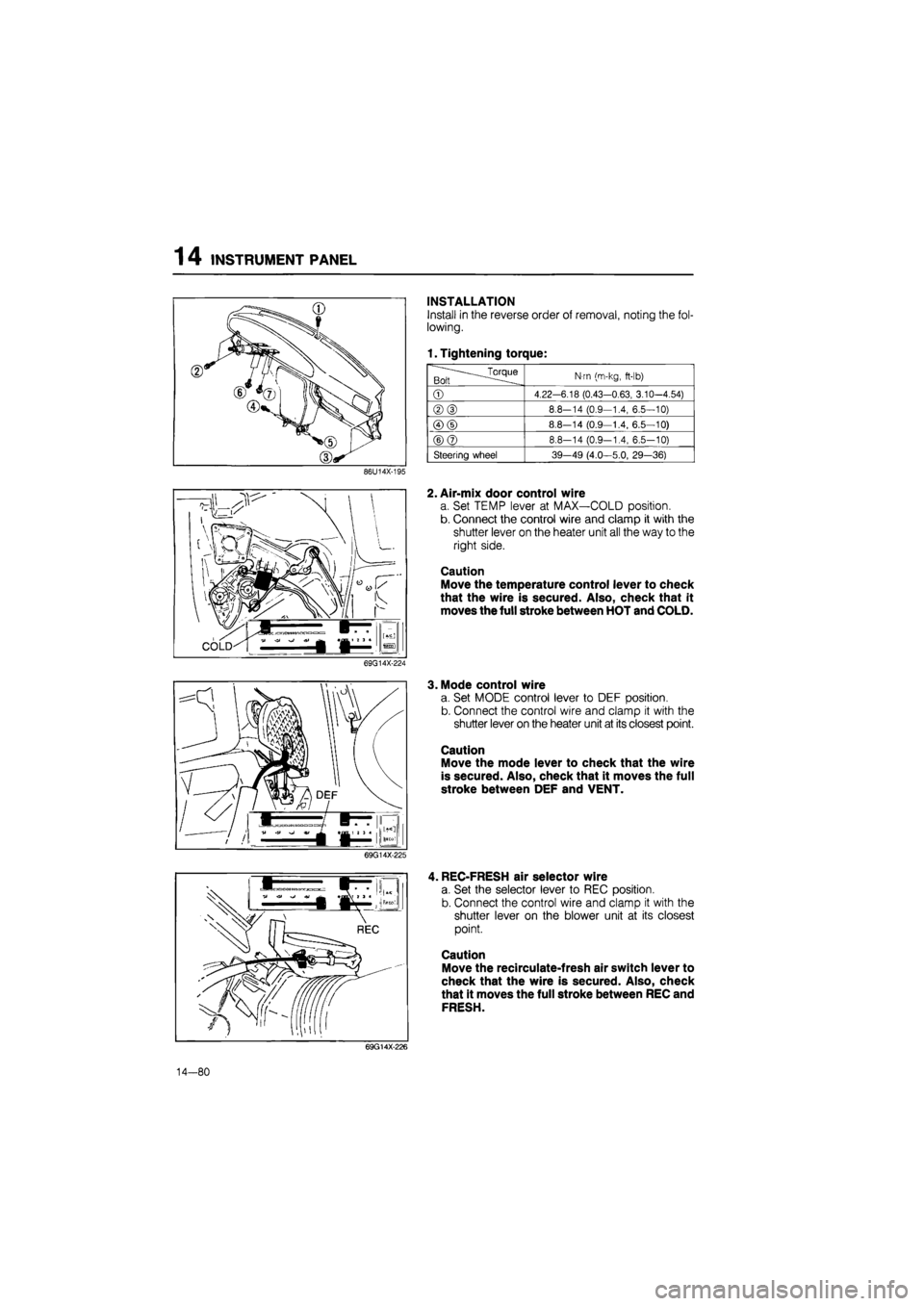
INSTALLATION
Install in the reverse order of removal, noting the fol-
lowing.
1. Tightening torque:
.^Torque Bolt
N-m (m-kg,
ft-lb)
©
4.22-6.18 (0.43-0.63, 3.10-4.54)
®(D
8.8-14 (0.9—1.4, 6.5—10)
©(D
8.8—14 (0.9—1.4, 6.5—10)
©@
8.8-14 (0.9-1.4, 6.5-10)
Steering wheel 39-49 (4.0—5.0, 29—36)
86U14X-195
2. Air-mix door control wire
a. Set TEMP lever at MAX—COLD position.
b. Connect the control wire and clamp it with the
shutter lever on the heater unit all the way to the
right side.
Caution
Move the temperature control lever to check
that the wire is secured. Also, check that it
moves the full stroke between HOT and COLD.
69G14X-224
3. Mode control wire
a. Set MODE control lever to DEF position.
b. Connect the control wire and clamp it with the
shutter lever on the heater unit at its closest point.
Caution
Move the mode lever to check that the wire
is secured. Also, check that it moves the full
stroke between DEF and VENT.
69G14X-225
, REC-FRESH air selector wire
a. Set the selector lever to REC position.
b. Connect the control wire and clamp it with the
shutter lever on the blower unit at its closest
point.
Caution
Move the recirculate-fresh air switch lever to
check that the wire is secured. Also, check
that it moves the full stroke between REC and
FRESH.
69G14X-226
14—80
Page 1727 of 1865
15 REAR WINDOW WIPER
CIRCUIT DIAGRAM
BATTERY MAIN FUSE X-01
X-01
REAR WIPER
&
WASHER SW GW [!]>• Control (Sectin Eb)
To Instrument Panel Light
D-01 Combination Sw [D]
LO
L B ±±±
LW
LB LR
D-02 Front Wiper Motor [F]
B
LR
LW
±±±
L LB L
D-03 Rear Wiper Sw [I] x
x GW
\±U±±
TTTT
(5 Door)
B
L BL
D-04 Rear Wiper Motor [R3]
^bGL (5Door)
D-05 Rear Washer Motor 1 D-06 Headlight Cleaner Sw
[
LY
RB
(5 Door)
LW GW
C-05 Washer Motor Assembly |Fj
LW
LY L
©I®T
T
LO
15-72
86U15X-127
Page 1732 of 1865
WINDSHIELD WIPER 15
CIRCUIT DIAGRAM
BATTERY
REAR WIPER
&
WASHER SW
GWIll^ Conlrol
. (Sectin ED)
To Instrument Panel Ligtil
D-01 Combination Sw
[
LO
L B ±±±
LW
LB LR
D-02 Front Wiper Motor [F]
B
LP LW
d±±
L LB L
D-03 Rear Wiper Sw
[I]
x
* GW
TTTT
(5 Door)
B
L BL RB
D-04 Rear Wiper Motor |R3]
(5 Door)
D-05 Rear Washer Motor [R]
^LG (5D°°r)
D-06 Headlight Cleaner Sw
LY
R0
LW GW
C-05 Washer Motor Assembly [F|
LW
LY L
f±±±1
wf 86U15X-135
15—77
Page 1809 of 1865

16 COOLING UNIT
COOLING UNIT
ON-VEHICLE INSPECTION OF EXPANSION
VALVE
1. Connect the manifold gauge set to the gauge fit-
tings on the low- and high-pressure pipes.
2. Operate the engine at 1,500 rpm and the air con-
ditioner at MAX. COOLING.
3. Check the low and high pressures.
Normal pressures are:
Low: 197—294 kPa
(2—3 kg/cm2, 28—43 psi)
High: 1472—1765 kPa
(15—18 kg/cm2, 210—260 psi)
If pressure is not as specified, replace the expansion
valve.
76G16X-623
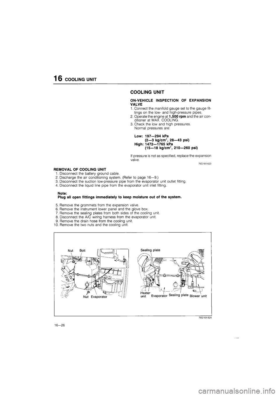
REMOVAL OF COOLING UNIT
1. Disconnect the battery ground cable.
2. Discharge the air conditioning system. (Refer to page 16—9.)
3. Disconnect the suction low-pressure pipe from the evaporator unit outlet fitting.
4. Disconnect the liquid line pipe from the evaporator unit inlet fitting.
Note:
Plug all open fittings immediately to keep moisture out of the system.
5. Remove the grommets from the expansion valve.
6. Remove the instrument lower panel and the glove box.
7. Remove the sealing plates from both sides of the cooling unit.
8. Disconnect the A/C wiring harness from the evaporator unit.
9. Remove the drain hose from the cooling unit.
10. Remove the two nuts and the cooling unit.
76G16X-624
16-26
Page 1811 of 1865
1 6 COOLING UNIT
INSTALLATION OF COOLING UNIT
1. Install the cooling unit by using the two nuts.
Note
Adjust and position the unit so that its con-
nections match those of the heater unit and
the blower unit.
2. Connect the drain hose.
76G16X-625
Sealing plate
Heater I _ .. ' . . - V
unit Evaporator dealing plate Blower unit
3. Join the connections on both sides by using the
seal plates.
4. Connect the A/C harness to the cooling unit.
76G16X-626
76G16X-627
5. Connect the liquid line high-pressure pipe and suc-
tion low-pressure pipe to the cooling unit.
Tightening torque:
15—22 Nm (1.5—2.5 m-kg, 11—18 ft-lb)
6. Install the instrument lower panel, shower duct and
glove box.
7. If the evaporator is replaced, add compressor oil
to the compressor.
Compressor oil: 50 cc (3.05 cu in)
16-28