1987 MAZDA 626 brakes
[x] Cancel search: brakesPage 216 of 1865

1 C TROUBLESHOOTING GUIDE
Problem Possible Cause Remedy Page
Insufficient power Insufficient compression Improper valve clearance Compression leakage from valve seat Seized valve stem Weak or broken valve spring Failed cylinder head gasket Cracked or distorted cylinder head Sticking, damaged, or worn piston ring Cracked or worn piston
Adjust
Repair
Replace Replace Replace Replace Replace Replace
1C-85 1C-50 1C-48 1C-52 1C—16 1C-47 1C-57 1C-56
Malfunction of fuel system Refer to Section 4D
Malfunction of Comprex supercharger Refer to Section 4D
Others Slipping clutch Dragging brakes Wrong size tires
Refer to Section 6 Refer to Section 11 Refer to Section 12
Abnormal
combustion
Malfunction of engine-related components
Improper valve clearance
Sticking or burned valve
Weak or broken valve spring
Carbon accumulation in combustion chamber
Adjust
Replace
Replace Eliminate carbon
1C-85
1C-48
1C-52
Malfunction of fuel system Refer to Section 4D
Malfunction of Comprex supercharger Refer to Section 4D
Engine noise Crankshaft or bearing related parts Excessive main bearing oil clearance Main bearing seized or heat-damaged Excessive crankshaft end play Excessive connecting rod bearing oil clearance Connecting rod bearing seized or heat-damaged
Replace or repair Replace
Replace or repair Replace or repair Replace
1C-64 1C-64 1C-65 1C-66 1C-66
Piston related parts Worn cylinder Worn piston or piston pin Seized piston Damaged piston ring Bent connecting rod
Replace or repair Replace
Replace Replace Replace
1C-55 1C-58 1C-56 1C-57 1C-59
Valves or timing related parts Excessive valve clearance Broken valve spring Excessive valve guide clearance Malfunction of timing belt tensioner
Adjust Replace Replace Replace
1C-85 1C-52 1C-48 1C-61
Malfunction of cooling system Refer to Section 3B
Malfunction of fuel system Refer to Section 4D
Malfunction of Comprex supercharger Refer to Section 4D
Others Malfunction of water pump bearing Improper drive-belt tension Malfunction of alternator bearing Exhaust gas leakage
Replace Adjust Replace Repair
1C-7
1C—47
76G01C-004
1C—4
Page 902 of 1865

7B TROUBLESHOOTING (G4A-EL)
Evaluation
Condition Possible Cause
No 1-2 up- or down-shift Stuck 1-2 shift solenoid valve
Stuck
1
-2 shift valve
No 2-3 up- or down-shift Stuck 2-3 shift solenoid valve Stuck 2-3 shift valve
No 3-OD up- or down-shift Stuck 3-4 shift solenoid valve Stuck 3-4 shift valve
No lock-up shift Stuck lock-up control solenoid valve Stuck lock-up control valve
Incorrect shift point Mis-adjusted throttle sensor Sticking shift valves
Excessive shift shock or slippage
Excessive shift shock Stuck accumulators Stuck or no one-way check orifice
Worn clutches, brakes, or one-way clutch
No engine braking effect Worn clutches or brakes
76G07B-035
Noise and vibration
Drive the vehicle in OD (lock-up), OD (no lock-up), 3rd (Hold) and check for abnormal noise or vibration.
Note
Abnormal noise and vibration can also be caused by the torque converter, drive shaft, or
differential. Therefore, checking of cause must be made with extreme care.
Kick-down
Drive the vehicle in OD, 3rd and 2nd gears and check that kick-down occurs for OD->3, OD->2, OD->1,
3->2, 3-+1, 2-> 1, and the shift points are as shown in the shift diagram.
S Range Test
Shift pattern
1. Shift the selector lever to S range and select the Economy mode.
2. Accelerate the vehicle and check that 1-2 and 2-3 up-shifts and down-shifts are obtained, and that
no overdrive and no lock-up are obtained.
Note
a) Inspections of shift shock and shift point are not necessary because these are the same
as those of the D Range Test.
b)ln S range, the shift patterns for Economy and Power modes are the same.
c) Shift points are the same as those of the D range (Power) shift diagram.
3. While driving in S range (Economy mode) and 3rd gear, select the Hold mode and check that 3rd
gear is held until the 3-2 down-shift point as shown in the S range (Hold) shift diagram is achieved.
4. Accelerate the vehicle with S range (Hold mode) and check that 2nd gear is held.
7B i—36
Page 1132 of 1865
7C TROUBLESHOOTING
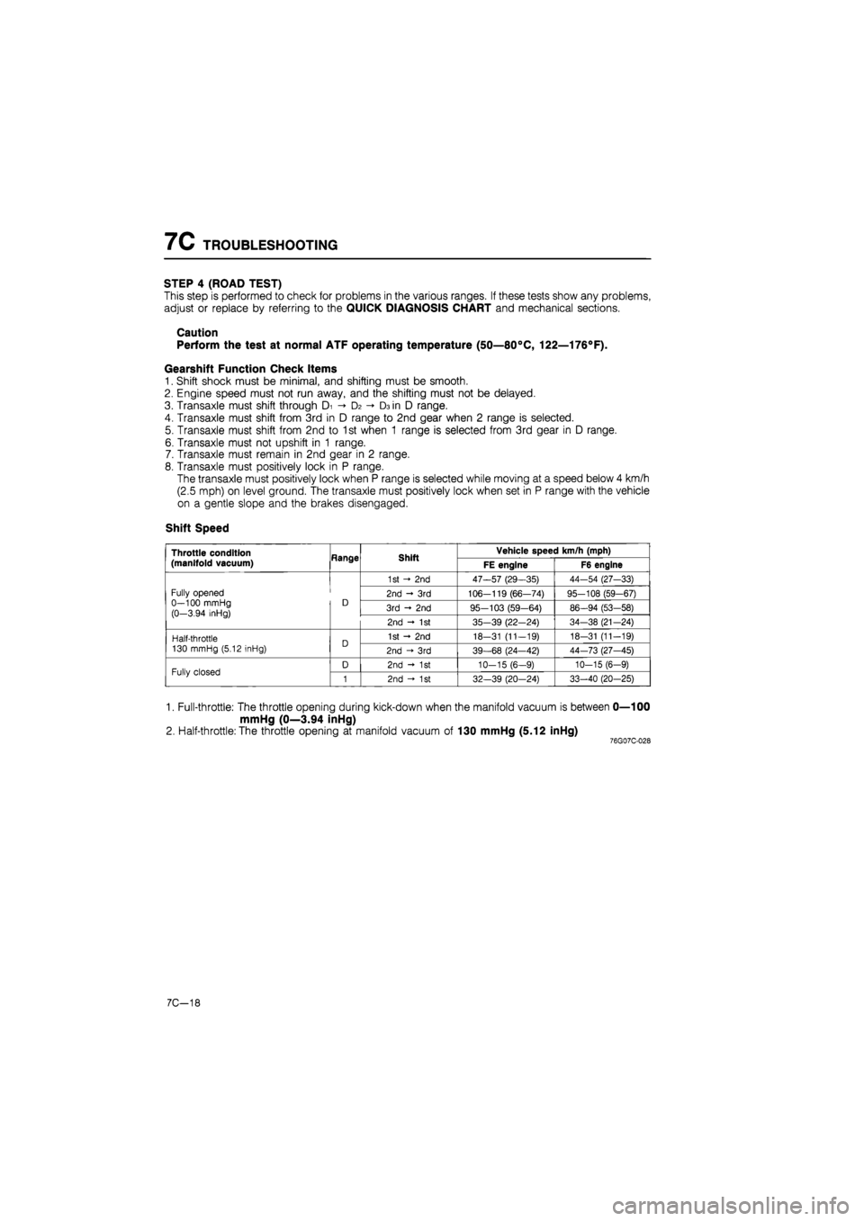
STEP 4 (ROAD TEST)
This step is performed to check for problems in the various ranges. If these tests show any problems,
adjust or replace by referring to the QUICK DIAGNOSIS CHART and mechanical sections.
Caution
Perform the test at normal ATF operating temperature (50—80°C, 122—176°F).
Gearshift Function Check Items
1. Shift shock must be minimal, and shifting must be smooth.
2. Engine speed must not run away, and the shifting must not be delayed.
3. Transaxle must shift through Di D2 -»• D3 in D range.
4. Transaxle must shift from 3rd in D range to 2nd gear when 2 range is selected.
5. Transaxle must shift from 2nd to 1st when 1 range is selected from 3rd gear in D range.
6. Transaxle must not upshift in 1 range.
7. Transaxle must remain in 2nd gear in 2 range.
8. Transaxle must positively lock in P range.
The transaxle must positively lock when P range is selected while moving at a speed below 4 km/h
(2.5 mph) on level ground. The transaxle must positively lock when set in P range with the vehicle
on a gentle slope and the brakes disengaged.
Shift Speed
Throttle condition
(manifold vacuum) Hange Shift Vehicle speed km/h (mph) Throttle condition
(manifold vacuum) Hange Shift FE engine F6 engine
Fully opened 0—100 mmHg (0-3.94 inHg)
D
1st - 2nd 47—57 (29—35) 44-54 (27-33)
Fully opened 0—100 mmHg (0-3.94 inHg)
D 2nd - 3rd 106-119 (66—74) 95-108 (59-67) Fully opened 0—100 mmHg (0-3.94 inHg)
D 3rd - 2nd 95-103 (59-64) 86-94 (53-58)
Fully opened 0—100 mmHg (0-3.94 inHg)
D
2nd - 1st 35-39 (22-24) 34-38 (21-24)
Half-throttle 130 mmHg (5.12 inHg) D 1st - 2nd 18-31 (11-19) 18-31 (11-19) Half-throttle 130 mmHg (5.12 inHg) D 2nd -»• 3rd 39-68 (24—42) 44-73 (27-45)
Fully closed D 2nd - 1st 10-15 (6-9) 10-15 (6-9) Fully closed 1 2nd - 1st 32—39 (20-24) 33-40 (20-25)
1. Full-throttle: The throttle opening during kick-down when the manifold vacuum is between 0—100
mmHg (0—3.94 inHg)
2. Half-throttle: The throttle opening at manifold vacuum of 130 mmHg (5.12 inHg) 76G07C-028
7C-18
Page 1278 of 1865
DRIVESHAFT 9
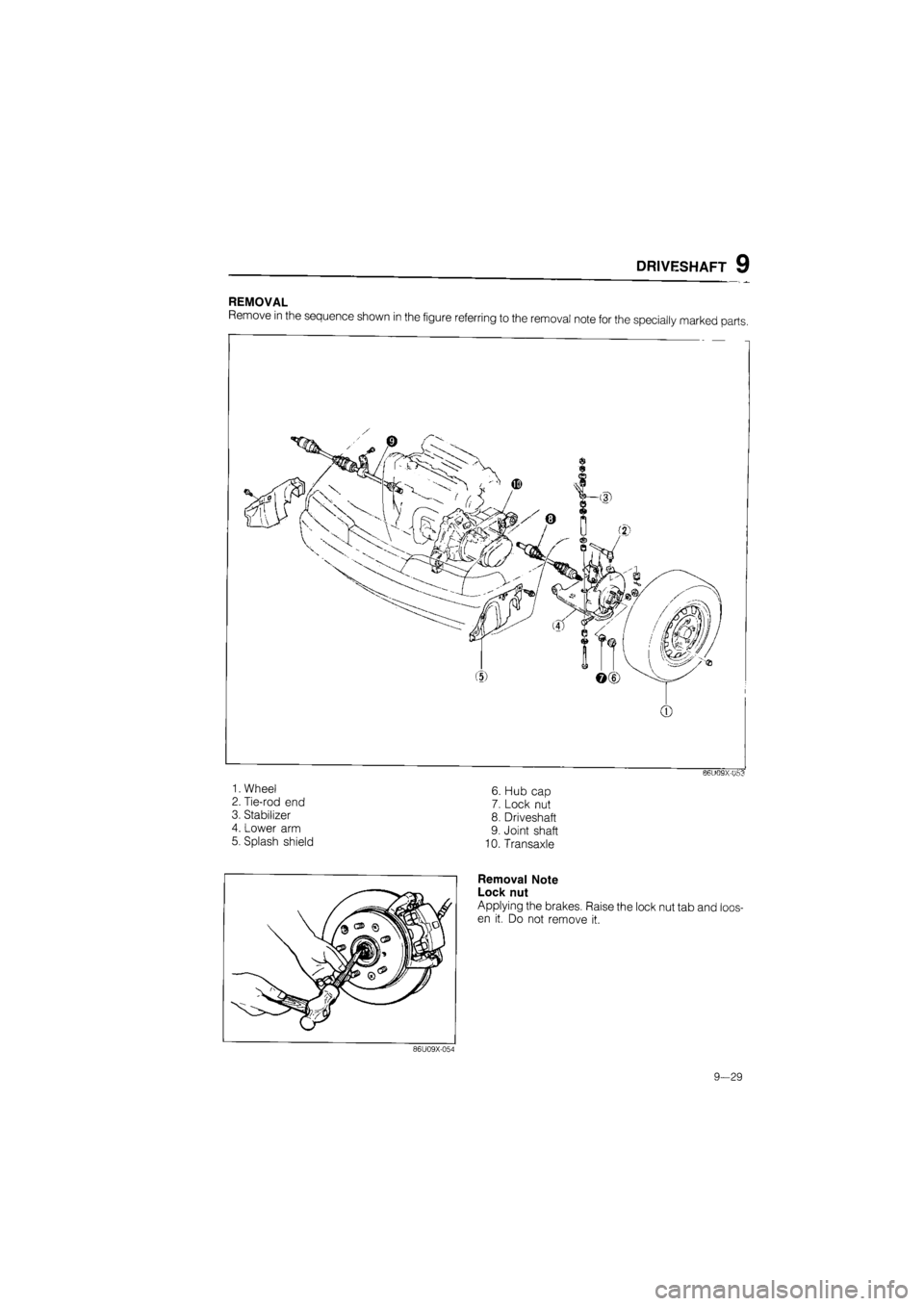
REMOVAL
Remove in the sequence shown in the figure referring to the removal note for the specially marked parts.
0
B6U09X-U53
6. Hub cap
7. Lock nut
8. Driveshaft
9. Joint shaft
10. Transaxle
Removal Note
Lock nut
Applying the brakes. Raise the lock nut tab and loos-
en it. Do not remove it.
1. Wheel
2. Tie-rod end
3. Stabilizer
4. Lower arm
5. Splash shield
86U09X-054
9-29
Page 1396 of 1865
1 1 OUTLINE
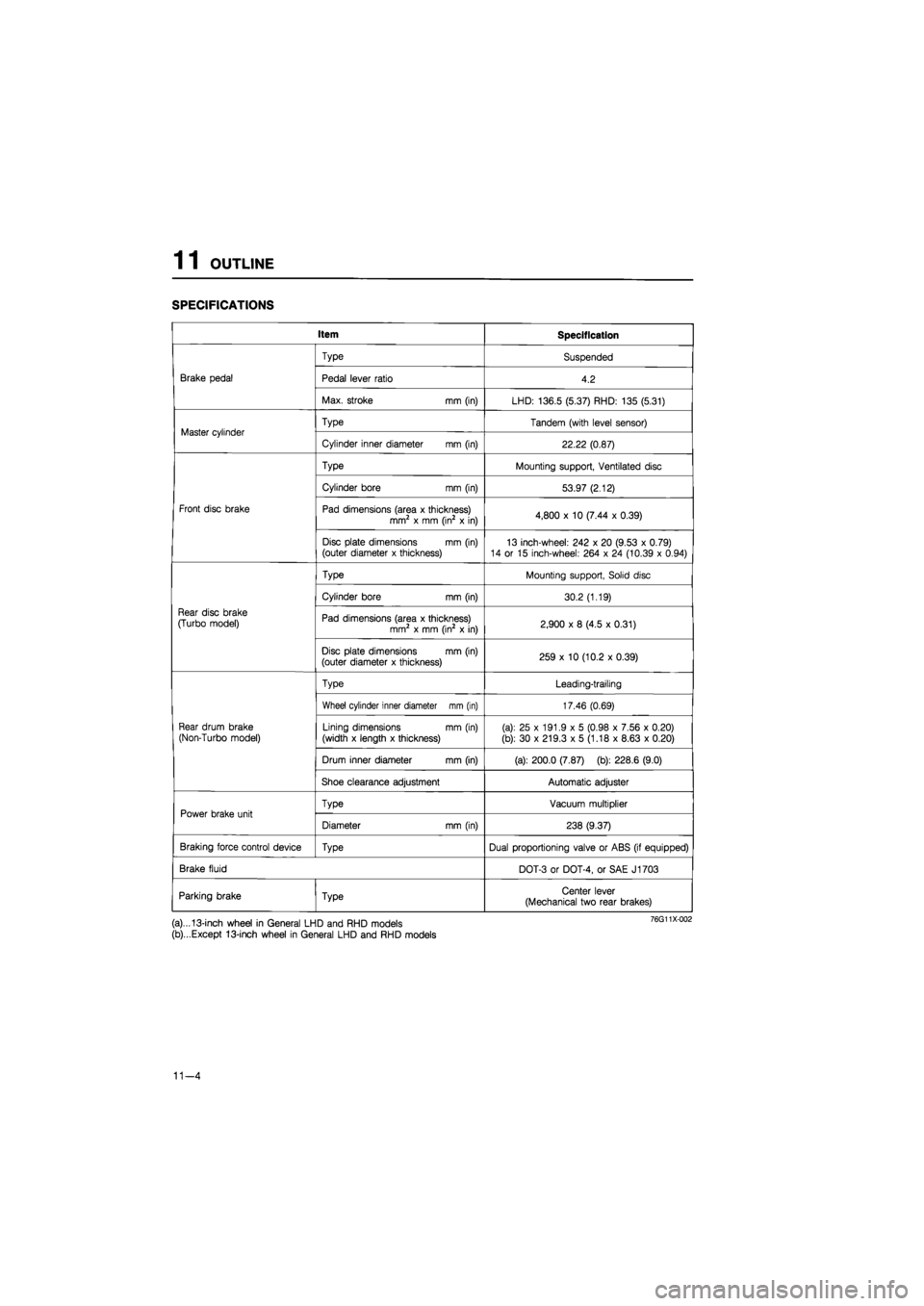
SPECIFICATIONS
Item Specification
Brake pedal
Type Suspended
Brake pedal Pedal lever ratio 4.2 Brake pedal
Max. stroke mm (in) LHD: 136.5 (5.37) RHD: 135 (5.31)
Master cylinder Type Tandem (with level sensor) Master cylinder
Cylinder inner diameter mm (in) 22.22 (0.87)
Front disc brake
Type Mounting support, Ventilated disc
Front disc brake
Cylinder bore mm (in) 53.97 (2.12)
Front disc brake Pad dimensions (area x thickness) mm2 x mm (in2 x in) 4,800 x 10 (7.44 x 0.39) Front disc brake
Disc plate dimensions mm (in) (outer diameter x thickness) 13 inch-wheel: 242 x 20 (9.53 x 0.79) 14 or 15 inch-wheel: 264 x 24 (10.39 x 0.94)
Rear disc brake
(Turbo model)
Type Mounting support, Solid disc
Rear disc brake
(Turbo model)
Cylinder bore mm (in) 30.2 (1.19)
Rear disc brake
(Turbo model) Pad dimensions (area x thickness) mm2 x mm (in2 x in) 2,900 x 8 (4.5 x 0.31)
Rear disc brake
(Turbo model)
Disc plate dimensions mm (in) (outer diameter x thickness) 259 x 10 (10.2 x 0.39)
Rear drum brake
(Non-Turbo model)
Type Leading-trailing
Rear drum brake
(Non-Turbo model)
Wheel cylinder inner diameter mm (in) 17.46 (0.69)
Rear drum brake
(Non-Turbo model) Lining dimensions mm (in)
(width x length x thickness) (a): 25 x 191.9 x 5 (0.98 x 7.56 x 0.20)
(b): 30 x 219.3 x 5 (1.18 x 8.63 x 0.20)
Rear drum brake
(Non-Turbo model)
Drum inner diameter mm (in) (a): 200.0 (7.87) (b): 228.6 (9.0)
Rear drum brake
(Non-Turbo model)
Shoe clearance adjustment Automatic adjuster
Power brake unit Type Vacuum multiplier Power brake unit
Diameter mm (in) 238 (9.37)
Braking force control device Type Dual proportioning valve or ABS (if equipped)
Brake fluid DOT-3 or DOT-4, or SAE J1703
Parking brake Type Center lever (Mechanical two rear brakes)
(a)...13-inch wheel in General LHD and RHD models
(b)...Except 13-inch wheel in General LHD and RHD models
11-4
Page 1397 of 1865
TROUBLESHOOTING GUIDE 1 1
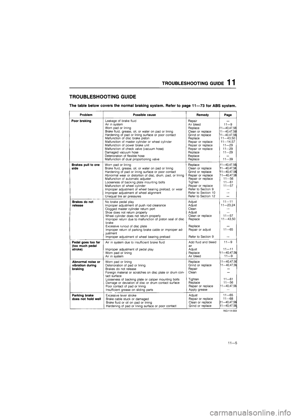
TROUBLESHOOTING GUIDE
The table below covers the normal braking system. Refer to page 11—73 for ABS system.
Problem Possible cause Remedy Page
Poor braking Leakage of brake fluid Air in system Worn pad or lining
Brake fluid, grease, oil, or water on pad or lining Hardening of pad or lining surface or poor contact Malfunction of disc brake piston Malfunction of master cylinder or wheel cylinder Malfunction of power brake unit
Malfunction of check valve (vacuum hose)
Damaged vacuum hose Deterioration of flexible hose Malfunction of dual proportioning valve
Repair Air bleed Replace
Clean or replace Grind or replace Replace Repair or replace Repair or replace Repair or replace Replace Replace Replace
11-9 11-40,47,56 11-40,47,56 11-40,47,56 11—43,50 11-14,57 11-29 11-29 11-29
11-39
Brakes pull to one
side
Worn pad or lining
Brake fluid, grease, oil, or water on pad or lining Hardening of pad or lining surface or poor contact Abnormal wear or distortion of disc, drum, pad, or lining Malfunction of automatic adjuster Looseness of backing plate mounting bolts Malfunction of wheel cylinder
Improper adjustment of wheel bearing preload, or wear Improper adjustment of wheel alignment Unequal tire air pressures
Replace Clean or replace Grind or replace Repair or replace Repair or replace Tighten
Repair or replace Refer to Section 9 Refer to Section 10 Refer to Section 12
11-40,47,56 11-40,47,56 11-40,47,56 11-40,47,56 11-56 11-61 11-57
Brakes do not
release
No brake pedal play
Improper adjustment of push rod clearance
Clogged master cylinder return port Shoe does not return properly Wheel cylinder does not return properly Improper return due to malfunction of piston seal of disc brake Excessive runout of disc plate Improper return of parking brake cable or improper ad-justment
Improper adjustment of wheel bearing preload
Adjust
Adjust
Clean
Adjust Clean or replace Replace
Replace Repair or adjust
Refer to Section 9
11-11
11—23,24
11-57 11—43,50
11-65
Pedal goes too far (too much pedal stroke)
Air in system due to insufficient brake fluid
Improper adjustment of pedal play Worn pad or lining Air in system
Add fluid and bleed air
Adjust Replace Air bleed
11—9
11—11 11-40,47,56 11-9
Abnormal noise or
vibration during
braking
Worn pad or lining Deterioration of pad or lining Brakes do not release
Foreign material or scratches on disc plate or drum con-tact surface
Looseness of backing plate or caliper mounting bolts Damage or deviation of disc or drum contact surface Poor contact of pad or lining Insufficient grease on sliding parts
Replace
Grind or replace
Repair
Clean
Tighten Replace Repair or replace Apply grease
11-40,47,56 11-40,47,56
11-61 11-56 11-40,47,56
Parking brake
does not hold well
Excessive lever stroke
Brake cable stuck or damaged
Brake fluid or oil on pad or lining Hardening of pad or lining surface or poor contact
Adjust
Repair or replace Clean or replace Grind or replace
11-65
11-68
11-40,47,56
11-40,47,56
76G11X-003
11—5
Page 1404 of 1865
1 1 BRAKE PEDAL
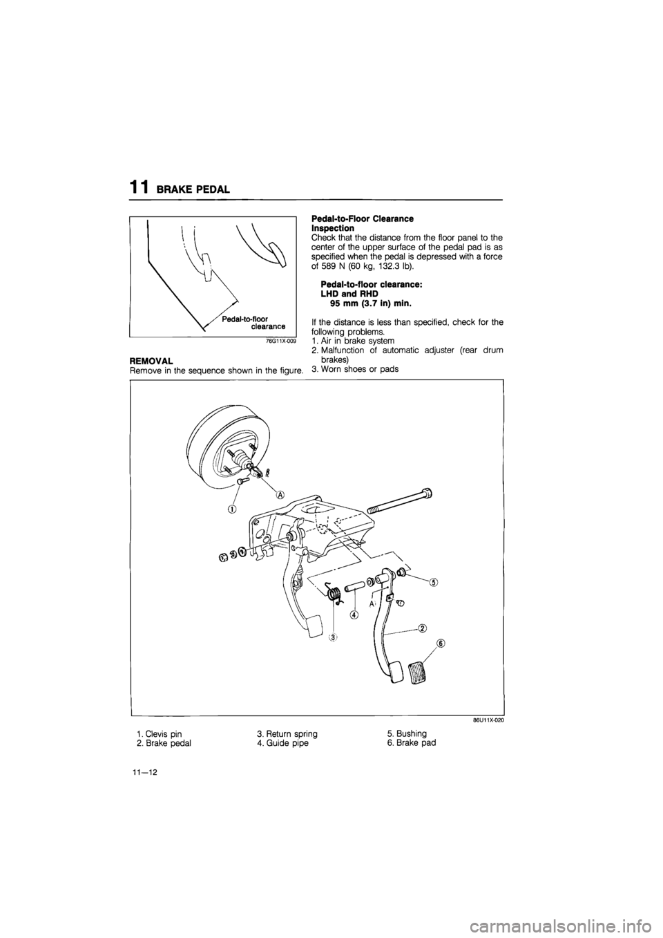
Pedal-to-floor clearance
76G11X-009
REMOVAL
Remove in the sequence shown in the figure.
Pedal-to-Floor Clearance
Inspection
Check that the distance from the floor panel to the
center of the upper surface of the pedal pad is as
specified when the pedal is depressed with a force
of 589 N (60 kg, 132.3 lb).
Pedal-to-floor clearance:
LHD and RHD
95 mm (3.7 in) min.
If the distance is less than specified, check for the
following problems.
1. Air in brake system
2. Malfunction of automatic adjuster (rear drum
brakes)
3. Worn shoes or pads
86U11X-020
1. Clevis pin
2. Brake pedal
3. Return spring
4. Guide pipe
5. Bushing
6. Brake pad
11—12
Page 1433 of 1865
FRONT DISC BRAKE 11
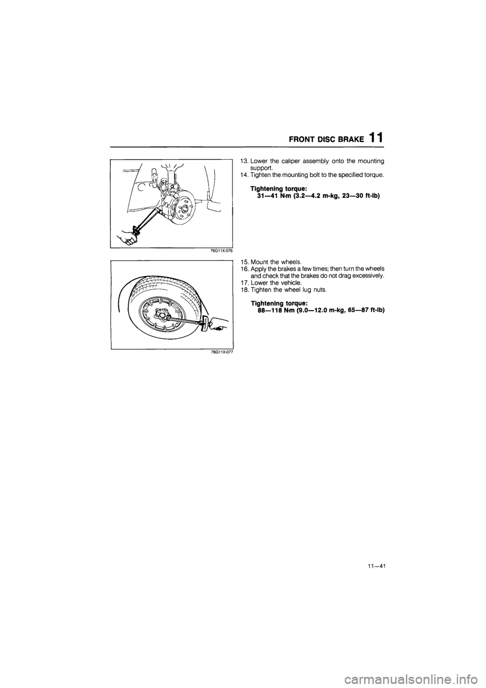
13. Lower the caliper assembly onto the mounting
support.
14. Tighten the mounting bolt to the specified torque.
Tightening torque:
31—41 N-m (3.2—4.2 m-kg, 23—30 ft-lb)
76G11X-076
15. Mount the wheels.
16. Apply the brakes a few times; then turn the wheels
and check that the brakes do not drag excessively.
17. Lower the vehicle.
18. Tighten the wheel lug nuts.
Tightening torque:
88—118 N-m (9.0—12.0 m-kg, 65—87 ft-lb)
76G11X-077
11—41