Page 45 of 1865

ON-VEHICLE INSPECTION 1 A
ON-VEHICLE INSPECTION
If the engine exhibits low power, poor fuel economy,
or poor idle, check the following points.
1. Ignition system (Refer to Section 5)
2. Compression
3. Fuel system (Refer to Section 4)
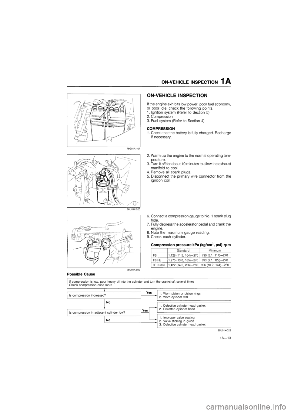
COMPRESSION
1. Check that the battery is fully charged. Recharge
if necessary.
76G01A-107
2. Warm up the engine to the normal operating tem-
perature.
3. Turn it off for about 10 minutes to allow the exhaust
manifold to cool.
4. Remove all spark plugs.
5. Disconnect the primary wire connector from the
ignition coil.
86U01X-020
6. Connect a compression gauge to No.
1
spark plug
hole.
7. Fully depress the accelerator pedal and crank the
engine.
8. Note the maximum gauge reading.
9. Check each cylinder.
Compression pressure kPa (kg/cm2, psi)-rpm
Standard Minimum
F6 1,128 (11.5, 164)—270 790 (8.1, 114)—270
F8-FE 1,275 (13.0, 185)—270 893 (9.1, 129)—270
FE 12-valve 1,422 (14.5, 206)—280 996 (10.2, 144)—280
76G01A-023
Possible Cause
86U01X-022
1A—13
Page 53 of 1865

1 A ON-VEHICLE MAINTENANCE (CYLINDER HEAD)
1. High-tension lead and spark plug
2. Accelerator cable
3. Throttle cable (ATX)
4. Air intake pipe (Fl)
5. Air cleaner assembly (carb.)
6. Fuel hose
7. Fuel pump (carb.)
8. Upper radiator hose
9. Heater hose
10. Brake vacuum hose
11. Canister hose (Fl, Middle East)
12. Three-way solenoid assembly
13. Engine harness connector and ground
14. Secondary air pipe assembly (except
General)
15. EGR pipe (Fl, Unleaded carb.)
16. Exhaust manifold insulator
17. Exhaust pipe
18. Exhaust manifold
19. Gusset plate (Fl)
20. Intake manifold bracket (Fl)
21. Intake manifold assembly
22. Distributor
23. A/C compressor and bracket
24. Upper timing belt cover
25. Timing belt tensioner spring
26. Timing belt
27. Cylinder head cover
28. Cylinder head and gasket 76G01A-031
Removal note
Fuel hose
Warning
a) Cover the hose with a rag because fuel will
spray out when disconnecting.
b) Keep sparks and open flame away from the
fuel area.
Plug the disconnected hoses to avoid fuel leakage.
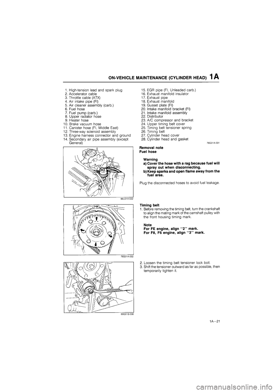
Timing belt
1. Before removing the timing belt, turn the crankshaft
to align the mating mark of the camshaft pulley with
the front housing timing mark.
Note
For FE engine, align "2" mark.
For F8, F6 engine, align "3" mark.
2. Loosen the timing belt tensioner lock bolt.
3. Shift the tensioner outward as far as possible, then
temporarily tighten it.
1A—21
Page 62 of 1865

1 A ON-VEHICLE MAINTENANCE (VALVE SEAL)
Installation note
Valve seal
1. Apply engine oil to the inside of the new valve seal.
2. Push it on gently with the SST.
86U01X-049
Valve spring
Cylinder head side
Valve spring
1. (12-valve)
Install the valve spring with the narrower pitch to-
ward the cylinder head side.
(8-valve)
Install the outer valve spring with the narrower pitch
toward the cylinder head side.
2. Install the valve keepers, and tap the end of the
valve stem lightly two or three times with a plastic
hammer to confirm that the keepers are all fully
seated.
76G01A-038
12-valve Rocker arm, rocker arm shaft
1. Remove the rocker arm shafts and camshaft caps.
2. (12-valve)
Assemble the rocker arms and springs to the shaft.
Note
a) The intake side shaft has twice as many oil
holes as the exhaust side shaft.
b) The stepped ends are the rear sides of both
intake and exhaust shafts.
76G01A-039
(8-valve)
Assemble the camshaft caps, rocker arms, and
springs, to the shafts.
Caution
Be sure both rocker arm shaft oil holes (in the
center camshaft cap) face each other.
76G01A-040
1A—30
Page 67 of 1865

REMOVAL 1A
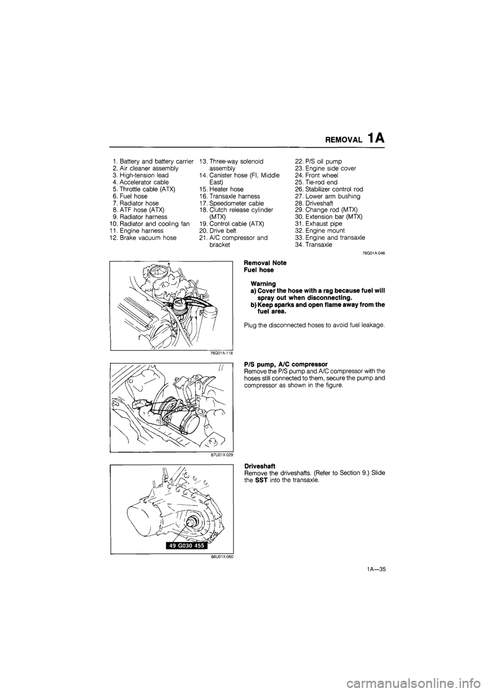
1. Battery and battery carrier 13. Three-way solenoid 22. P/S oil pump
2. Air cleaner assembly assembly 23. Engine side cover
3. High-tension lead 14. Canister hose (Fl, Middle 24. Front wheel
4. Accelerator cable East) 25. Tie-rod end
5. Throttle cable (ATX) 15. Heater hose 26. Stabilizer control rod
6. Fuel hose 16. Transaxle harness 27. Lower arm bushing
7. Radiator hose 17. Speedometer cable 28. Driveshaft
8. ATF hose (ATX) 18. Clutch release cylinder 29. Change rod (MTX)
9. Radiator harness (MTX) 30. Extension bar (MTX)
10. Radiator and cooling fan 19. Control cable (ATX) 31. Exhaust pipe
11. Engine harness 20. Drive belt 32. Engine mount
12. Brake vacuum hose 21. A/C compressor and 33. Engine and transaxle
bracket 34. Transaxle
76G01A-046
Removal Note
Fuel hose
Warning
a) Cover the hose with a rag because fuel will
spray out when disconnecting.
b) Keep sparks and open flame away from the
fuel area.
Plug the disconnected hoses to avoid fuel leakage.
76G01A-11E
P/S pump, A/C compressor
Remove the P/S pump and A/C compressor with the
hoses still connected to them, secure the pump and
compressor as shown in the figure.
67U01X-029
Driveshaft
Remove the driveshafts. (Refer to Section 9.) Slide
the SST into the transaxle.
86U01X-060
1A—35
Page 69 of 1865
DISASSEMBLY (AUXILIARY PARTS) 1 A
1. Oil level gauge
2. P/S oil pump bracket
3. Secondary air pipe assembly (except
General)
4. EGR pipe (Fl, Unleaded carb.)
5. Exhaust manifold insulator
6. Exhaust manifold assembly
7. Coolant inlet pipe and bypass pipe
8. Engine hanger
9. Alternator
10. Alternator strap and bracket
11. Engine mount bracket
12. Distributor and high-tension lead
13. Spark plug
14. Thermostat and thermostat cover
15. Intake manifold bracket (Fl)
16. Intake manifold assembly
17. Oil filter
18. Oil cooler (8-valve...only ECE, 12-valve)
19. Oil pressure switch
76G01A-047
Disassembly Note
Engine hanger
Remove the exhaust manifold; then connect the SST
to the engine.
76G01A-120
69G01X-000
1A—37
Page 82 of 1865
INSPECTION AND REPAIR 1 A
86U01X-082
Valve guide
Cylinder head
76G01A-057
(2) Method No. 2
Measure the valve stem play at a point close
to the valve guide with the valve lifted slightly
off the valve seat.
Clearance
IN : 0.025—0.060 mm (0.0010—0.0024 in)
EX: 0.030—0.065 mm (0.0012—0.0026 in)
Maximum: 0.20 mm (0.0079 in)
7. If the clearance exceeds the maximum, replace the
valve and/or valve guide.
8. Check that the valve guide projection height
(dimension A in the figure). Replace if necessary.
Height:
19.8—20.3 mm (0.780—0.799 in)... 12-valve
19.1—19.6 mm (0.752—0.772 in)...8-valve
Replacement of valve guide
Note
Although the shapes of the intake and exhaust
valve guides are different, use the exhaust
valve guide on both sides as a replacement.
86U01X-214
Removal
1. Gradually heat the cylinder head in water to ap-
prox. 90°C (194°F).
76G01A-131
1A—50
Page 107 of 1865
ASSEMBLY (CYLINDER HEAD) 1 A
86U01X-148
86U01X-149
86U01X-150
Camshaft
1. Apply a liberal amount of engine oil to the journals
and bearings.
2. Place the camshaft in position with the dowel pin
facing straight up.
Hydraulic Lash Adjuster (HLA)
1. Pour engine oil into the oil reservoir in the rocker
arm.
2. Apply engine oil to the new HLA.
3. Carefully install the HLA into the rocker arm.
Caution
Be careful not to damage the O-ring when in-
stalling the HLA.
Camshaft Cap, Rocker Arm and Shaft Assembly
1. Assemble the rocker arm and shaft assembly as
shown in the figure.
Note
a) The intake side shaft has twice as many oil
holes as the exhaust side shaft.
b)The stepped ends are the rear of the shafts.
2. Apply silicon sealant to the shaded areas shown
in the figure.
76G01A-140
1 A—75
Page 122 of 1865
1 A ASSEMBLY (AUXILIARY PARTS)
76G01A-093
76G01A-094
76G01A-095
Exhaust Manifold Assembly
1. Place the new gaskets in position with the ridge
facing the cylinder head.
2. Install the exhaust manifold assembly.
3. Tighten the nuts in two or three steps.
Tightening torque:
34—49
N
m (3.5—5.0 m-kg, 25—36 ft-lb)
Exhaust Manifold Insulator
Install the exhaust manifold insulator.
Tightening torque:
19—30
N
m (1.9—3.1 m-kg, 14—22 ft-lb)
EGR Pipe
Install the EGR pipe.
Tightening torque:
34—44 Nm (3.5—4.5 m-kg, 25—33 ft-lb)
Secondary Air Pipe Assembly
Install the secondary air pipe assembly.
Tightening torque:
16—23 Nm (1.6—2.3 m-kg, 12—17 ft-lb)
P/S Oil Pump Bracket
Install the P/S oil pump bracket.
Tightening torque:
37—63 Nm (3.8—6.4 m-kg, 27—46 ft-lb)
86U01X-178
1A—90