Page 1618 of 1865
HEADLINER 14
HEADLINER
STRUCTURAL VIEW
Coupe/MX-6
Sliding sunroof
1. Rearview mirror and
overhead console
2. Sunvisor
3. Center adapter
4. Assist handle
5. Interior light
6. Front header trim
7. Front pillar trim
8. Rear pillar trim
9. Rear header trim
10. Insulator
11. Headliner
86U14X-159
14—67
Page 1619 of 1865
14 HEADLINER
Sedan and Hatchback
Sliding sunroof
86U14X-160
1. Rearview mirror and
overhead console
2. Sunvisor
3. Center adapter
4. Assist handle
5. Interior light
6. Front header trim
7. Front pillar trim
8. Rear pillar trim
9. Rear header trim
10. Insulator
11. Headliner
14—68
Page 1620 of 1865
HEADLINER 14
REMOVAL
1. Remove the overhead console cover.
2. Remove the rearview mirror.
3. Remove the overhead console mounting screws.
4. Disconnect the connectors and remove the over-
head console.
86U14X-161
69G14X-241
5. Remove the sunvisors.
6. Remove the center adapters.
7. Remove the interior light lens with a protected small
screwdriver.
86U14X-162
8. Remove the interior light mounting screws and dis-
connect the connector.
9. Remove the interior light.
86U14X-163
14—69
Page 1623 of 1865
14 HEADLINER
18. Remove the fasteners and remove the headliner.
86U14X-172
INSTALLATION
Install in the reverse order of removal, noting the fol-
lowing.
Note
Align the trim and clip positions, then install
the clips by striking them lightly.
86U14X-173
14—72
Page 1629 of 1865
1 4 INSTRUMENT PANEL
86U14X-187
86U14X-188
86U14X-189
18. Remove the screws and pull the panel outward.
19. Disconnect the connectors and remove the switch
panel.
20. Remove the screws and remove the glove box.
21. Disconnect the glove box light connector.
22. Remove the center panel.
23. Remove the screws and slide out the heater con-
trol assembly.
24. Disconnect the control wires at the DEF, MAX-
COLD and REC positions (lever type control).
Note
Disconnect the connectors at the rear of the
control (Logicon type).
25. Remove the center cap.
26. Remove the instrument panel mounting bolt.
86U14X-190
14-78
Page 1637 of 1865
1 4 SLIDING SUNROOF
3. After moving the guide bracket assembly slightly
toward the rear, tighten the screw, taking care
regarding the direction the set plate faces.
76U14X-059
Ipi
" (E) ling
Notch jilting Cam
—+ * ) siii
Align the projection of the tilting cam and the slit
in the set plate.
76U14X-060
5. Check that the limit switches (LS1 and LS2) of the
motor are as shown in the figure at the OFF po-
sition.
Note
a) Be careful of the cam position.
b) Use the handle to position it correctly.
76U14X-061
6. Install the motor assembly.
Note
There are 2 types of screws, long and short.
Be sure to use the correct ones.
7. Connect the wiring of the motor assembly and the
motor switch.
76U14X-062
14-86
Page 1648 of 1865
HEADLIGHT WASHER 14
HEADLIGHT WASHER
REMOVAL AND INSTALLATION
1. Remove in the sequence shown in the figure.
2. Install in the reverse order of removal.
76G14X-039
1. Bracket
2. Coolant reservoir
3. Bracket
4. Washer pump
5. Washer nozzles
6. Clips
7. Hose
8. Joint
9. Washer tank
14—97
Page 1656 of 1865

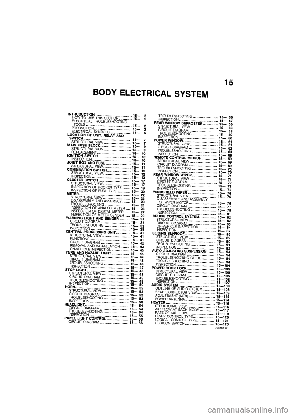
15
BODY ELECTRICAL SYSTEM
INTRODUCTION 15- 2 HOW TO USE THIS SECTION 15— 2 ELECTRICAL TROUBLESHOOTING TOOLS 15- 2 PRECAUTION 15— 3 ELECTRICAL SYMBOLS 15- 6 LOCATION OF UNIT, RELAY AND SWITCH 15- 7
STRUCTURAL VIEW 15— 7 MAIN FUSE BLOCK 15- 9 STRUCTURAL VIEW 15— 9 REPLACEMENT 15—10 IGNITION SWITCH 15—10
INSPECTION 15— 10 JOINT BOX AND FUSE 15—11
STRUCTURAL VIEW 15—11
COMBINATION SWITCH 15-12 STRUCTURAL VIEW 15- 12 INSPECTION 15— 13 CLUSTER SWITCH 15—17 STRUCTURAL VIEW 15— 17 INSPECTION OF ROCKER TYPE 15— 19
INSPECTION OF PUSH TYPE 15— 20 METER 15— 22 STRUCTURAL VIEW 15— 22 DISASSEMBLY AND ASSEMBLY 15— 23
TROUBLESHOOTING 15— 24 INSPECTION OF ANALOG METER .... 15— 26 INSPECTION OF DIGITAL METER 15— 27
INSPECTION OF METER SENDER 15— 29 WARNING LIGHT AND SENDER 15- 31 CIRCUIT DIAGRAM 15— 31
TROUBLESHOOTING 15- 32 INSPECTION 15— 39 CENTRAL PROCESSING UNIT 15— 41 STRUCTURAL VIEW 15— 41 FUNCTIONS 15- 41 CIRCUIT DIAGRAM 15— 42 REMOVAL AND INSTALLATION 15— 43
ON-VEHICLE INSPECTION 15- 43 TURN AND HAZARD LIGHT 15- 44 STRUCTURAL VIEW 15— 44 CIRCUIT DIAGRAM 15— 45
TROUBLESHOOTING 15- 46 INSPECTION 15— 47 STOP LIGHT 15— 48
STRUCTURAL VIEW 15— 48 CIRCUIT DIAGRAM 15— 49
TROUBLESHOOTING 15- 49 INSPECTION 15- 50 HORN 15— 52 STRUCTURAL VIEW 15— 52 CIRCUIT DIAGRAM 15— 52 TROUBLESHOOTING 15— 53 INSPECTION 15-53 HEADLIGHT 15— 54 CIRCUIT DIAGRAM 15— 54 TROUBLESHOOTING 15— 54 INSPECTION 15— 55 PANEL LIGHT CONTROL 15— 56 CIRCUIT DIAGRAM 15— 56
TROUBLESHOOTING 15_ 5fi INSPECTION 17 REAR WINDOW DEFROSTER ..i".'! 15- 58
STRUCTURAL VIEW 15-5fl CIRCUIT DIAGRAM 15_ «
TROUBLESHOOTING '.. 15_ 59
INSPECTION
15-60 POWER WINDOW 15-61 STRUCTURAL VIEW il_ «1 CIRCUIT DIAGRAM 15_ 62 TROUBLESHOOTING 15- «3 INSPECTION 15-66 REMOTE CONTROL MIRROR ........15- 69 STRUCTURAL VIEW 15-69 CIRCUIT DIAGRAM 15_ 69
TROUBLESHOOTING 15_ 70 INSPECTION 15_ 70 REAR WINDOW WIPER 15_ 71 STRUCTURAL VIEW 15-71 CIRCUIT DIAGRAM .'.'.'...' 15_ 72
TROUBLESHOOTING 15-73 INSPECTION 15-75 WINDSHIELD WIPER 15-76 STRUCTURAL VIEW ' ' 15— 7e
DISASSEMBLY AND ASSEMBLY OF WIPER MOTOR 15_ 76 CIRCUIT DIAGRAM 15-77 TROUBLESHOOTING " " 15— 70 INSPECTION 15-81 CRUISE CONTROL SYSTEM 15- 82 STRUCTURAL VIEW 15-82 CIRCUIT DIAGRAM 15-83 ON-VEHICLE INSPECTION \..\m 15- 84 INSPECTION 15-87 SLIDING SUNROOF 15-89 STRUCTURAL VIEW 15_ 89 CIRCUIT DIAGRAM i5_ 90
TROUBLESHOOTING 15— 91 INSPECTION 15_ 90 AUTO ADJUSTING SUSPENSION 15— 94
CIRCUIT DIAGRAM 15- 94
TROUBLESHOOTING GUIDE 15— 94
TROUBLESHOOTING 15— 94
INSPECTION 15-104
POWER DOOR LOCK 15-105
STRUCTURAL VIEW 15-105
CIRCUIT DIAGRAM 15-105
TROUBLESHOOTING 15-106 INSPECTION 15-107 AUDIO SYSTEM " 15_108 OUTLINE OF AUDIO SYSTEM 15-108 REAR CONNECTOR VIEW 15-109 ADJUSTMENT (MTR) 15—114 POWER ANTENNA 15-114 HEATER J
STRUCTURAL VIEW 15-116 AIR FLOW AT EACH MODE 15-117 RATE OF AIR FLOW 15-119 LEVER CONTROL TYPE 15-120 LOGICAL CONTROL
TYPE
15—121 LOGICON SWITCH 15—123
76G15X-001