Page 1813 of 1865

1 6 A/C RELAY
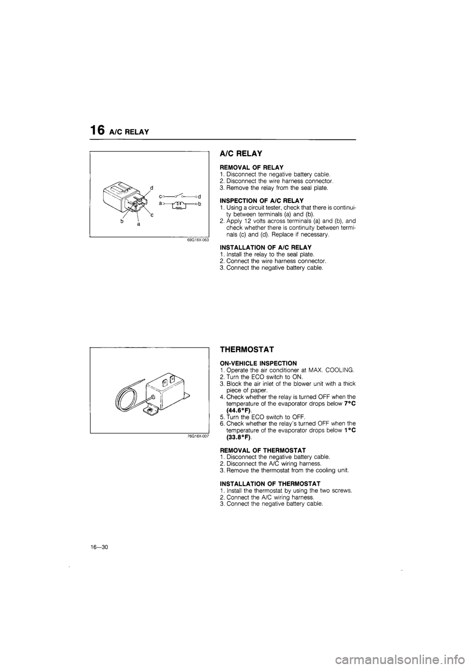
A/C RELAY
REMOVAL OF RELAY
1. Disconnect the negative battery cable.
2. Disconnect the wire harness connector
3. Remove the relay from the seal plate.
INSPECTION OF A/C RELAY
1. Using a circuit tester, check that there is continui-
ty between terminals (a) and (b).
2. Apply 12 volts across terminals (a) and (b), and
check whether there is continuity between termi-
nals (c) and (d). Replace if necessary.
INSTALLATION OF A/C RELAY
1. Install the relay to the seal plate.
2. Connect the wire harness connector.
3. Connect the negative battery cable.
THERMOSTAT
ON-VEHICLE INSPECTION
1. Operate the air conditioner at MAX. COOLING.
2. Turn the ECO switch to ON.
3. Block the air inlet of the blower unit with a thick
piece of paper.
4. Check whether the relay is turned OFF when the
temperature of the evaporator drops below 7°C
(44.6°F).
5. Turn the ECO switch to OFF.
6. Check whether the relay's turned OFF when the
temperature of the evaporator drops below 1°C
(33.8°F).
REMOVAL OF THERMOSTAT
1. Disconnect the negative battery cable.
2. Disconnect the A/C wiring harness.
3. Remove the thermostat from the cooling unit.
INSTALLATION OF THERMOSTAT
1. Install the thermostat by using the two screws.
2. Connect the A/C wiring harness.
3. Connect the negative battery cable.
76G16X-007
16-30
Page 1830 of 1865

30 TECHNICAL DATA
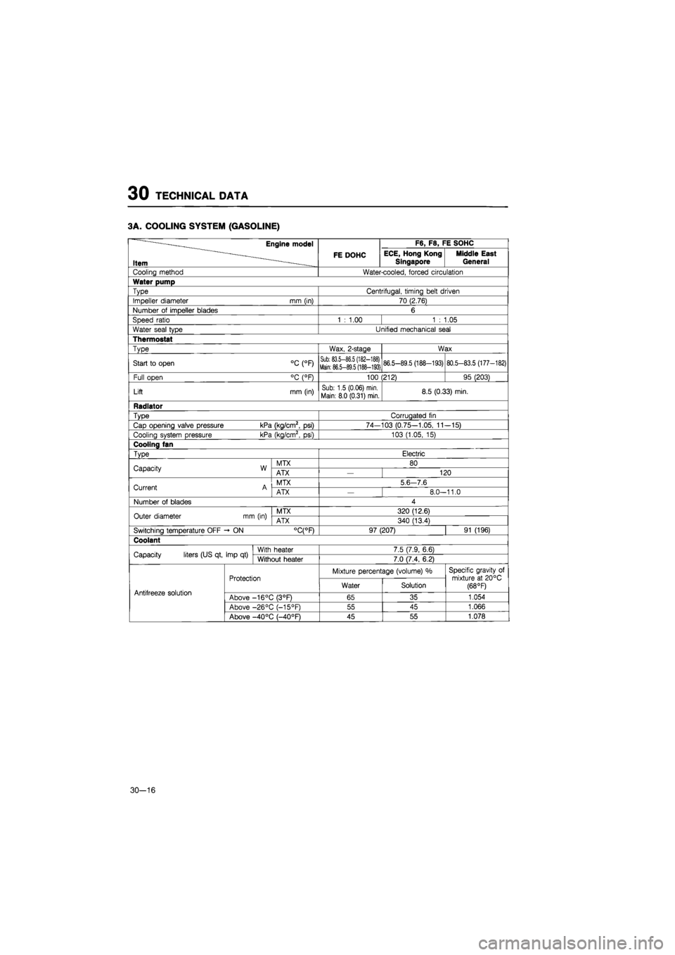
3A. COOLING SYSTEM (GASOLINE)
Engine model F6, F8, FE SOHC
Item FE DOHC ECE, Hong Kong
Singapore Middle East General
Cooling method Water-cooled, forced circulation
Water pump
Type Centrifugal, timing belt driven
Impeller diameter mm (in) 70 (2.76)
Number
of
impeller blades 6
Speed ratio 1
:
1.00 1
:
1.05
Water seal type Unified mechanical seal
Thermostat
Type Wax, 2-stage Wax
Start
to
open °C (°F) Sub: 83.5-86.5 (182-188) Main: 86.5-89.5 (188-193) 86.5-89.5 (188-193) 80.5-83.5 (177-182)
Full open °C (°F) 100 (212) 95 (203)
Lift mm (in) Sub: 1.5 (0.06) min.
Main: 8.0 (0.31) min. 8.5 (0.33) min.
Radiator
Type Corrugated
fin
Cap opening valve pressure kPa (kg/cm2,
psi)
74-103 (0.75-1.05,
11
-15)
Cooling system pressure kPa (kg/cm2,
psi)
103 (1.05,
15)
Cooling fan
Type Electric
Capacity W MTX 80 Capacity W ATX 120
Current A MTX 5
6 7.6
Current A ATX
—
8.0-11.0
Number
of
blades 4
Outer diameter mm (in) MTX 320 (12.6) Outer diameter mm (in) ATX 340 (13.4)
Switching temperature OFF -
ON
°C(°F) 97 (207) 91 (196)
Coolant
Capacity liters (US qt, Imp
qt)
With heater 7.5 (7.9, 6.6) Capacity liters (US qt, Imp
qt)
Without heater 7.0 (7.4, 6.2)
Protection Mixture percentage (volume)
%
Specific gravity
of
mixture
at
20°C (68 °F) Antifreeze solution
Protection Water Solution
Specific gravity
of
mixture
at
20°C (68 °F) Antifreeze solution Above -16°C (3°F) 65 35 1.054
Above -26°C (-15°F) 55 45 1.066
Above -40 °C (—40°F) 45 55 1.078
30-16
Page 1831 of 1865

TECHNICAL DATA 30
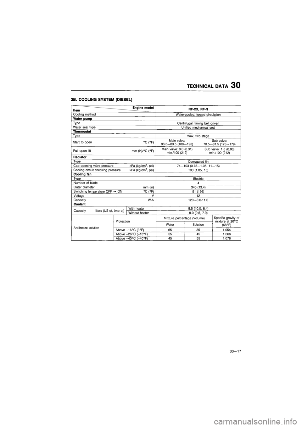
3B. COOLING SYSTEM (DIESEL)
Item Engine model RF-CX, RF-N
Cooling method Water-cooled, forced circulation
Water pump
Type Centrifugal, timing belt driven
Water seal type Unified mechanical seal
Thermostat
Type Wax, two stage
Start
to
open °C (°F) Main valve:
86.5-89.5 (188-193)
78.5-
Sub valve: 81.5 (173-179)
Full open lift mm (in)/°C (°F) Main valve: 8.0 (0.31) Sub valve: 1.5 (0.06) min./100 (212) min./100 (212)
Radiator
Type Corrugated
fin
Cap opening valve pressure kPa (kg/cm2,
psi)
74—103 (0.75—1.05,
11
-15)
Cooling circuit checking pressure kPa (kg/cm2,
psi)
103 (1.05,
15)
Cooling fan
Type Electric
Number
of
blade 4
Outer diameter mm (in) 340 (13.4)
Switching temperature OFF -»
ON
°C (°F) 91 (196)
Voltage V 12
Capacity W-A 120-8.0-11.0
Coolant
Capacity liters (US qt, Imp
qt)
With heater 9.5 (10.0, 8.4) Capacity liters (US qt, Imp
qt)
Without heater 9.0 (9.5, 7.9)
Protection Mixture percentage (Volume) Specific gravity
of
mixture
at
20°C (68 °F) Antifreeze solution
Protection Water Solution
Specific gravity
of
mixture
at
20°C (68 °F) Antifreeze solution Above -16°C (3°F) 65 35 1.054
Above -26°C (-15°F) 55 45 1.066
Above -40°C (-40°F) 45 55 1.078
30-17