Page 954 of 1865
7B DISASSEMBLY
DISASSEMBLY
DISASSEMBLY-STEP 1
Components
1. Torque converter
2. Oil pump shaft
3. Oil level gauge and oil filler tube
4. Pulse generator, fluid temperature switch,
and inhibitor switch
5. Solenoid connector
6. Wire harnesses
7. Harness clip
86U07B-116
8. Oil pipes, oil hoses, and switch box
9. Oil pan and gasket
10. Oil strainer and O-ring
11. Control valve body cover and gasket
12. Throttle cable
13. Solenoid connector (Valve body side)
14. Control valve body
15. Oil pump and gasket
7B-88
Page 957 of 1865
DISASSEMBLY 7B
6 G4A-EL
Remove the pulse generator, fluid temperature
switch, and inhibitor switch.
G4A-HL
Remove the inhibitor switch.
76GQ7B-123
7. Disconnect the solenoid connector.
8. Remove the harnesses.
76G07B-124
9. G4A-EL
Remove the harness clip, then remove the oil
pipes, oil hoses and switch box as an assembly.
Note
Remove the ball from the case.
76G07B-125
G4A-HL
Remove the oil pipe.
Note Remove the ball from the case.
76G07B-126
7B—91
Page 1079 of 1865

ASSEMBLY 7B
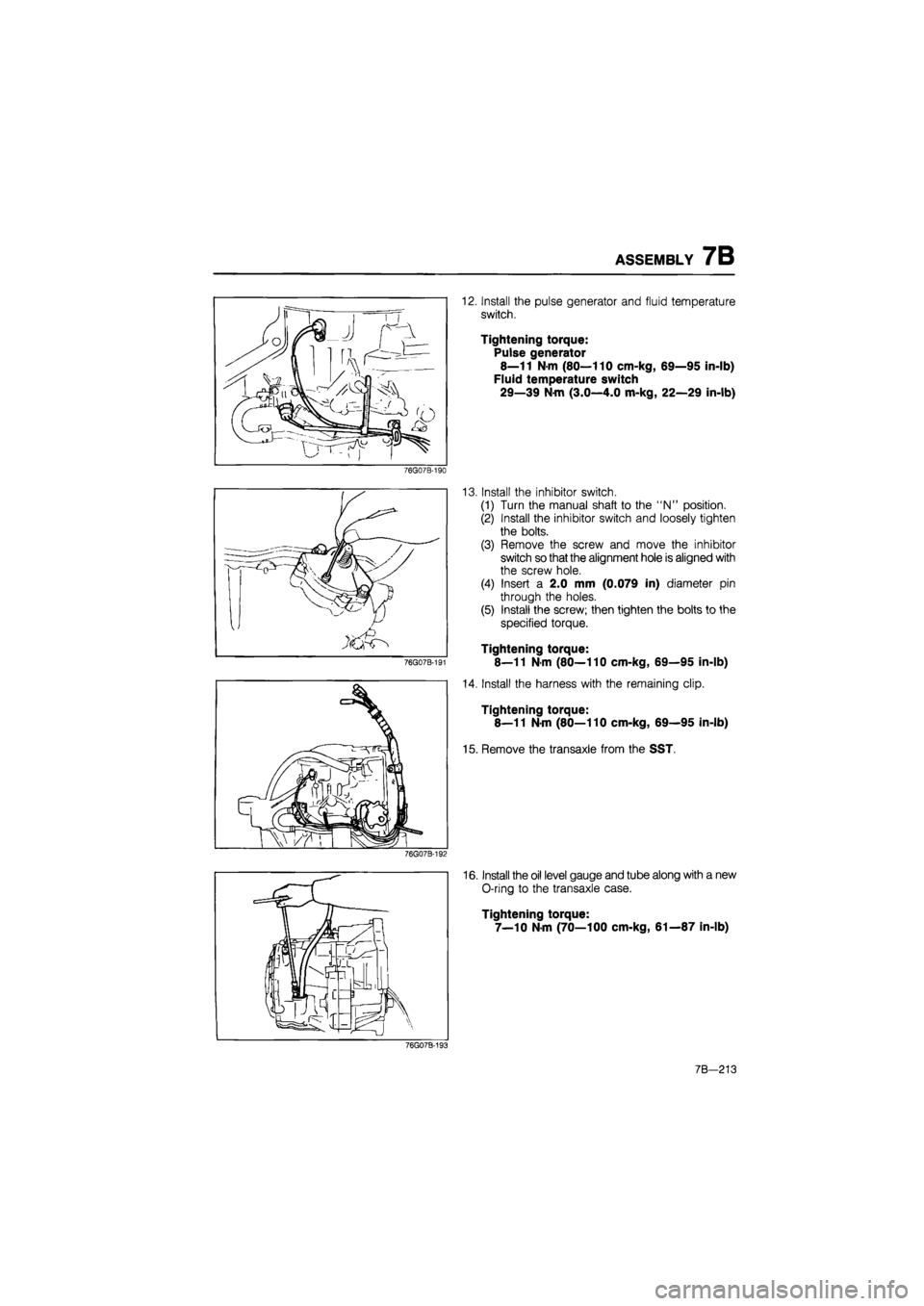
12. Install the pulse generator and fluid temperature
switch.
Tightening torque:
Pulse generator
8—11 N-m (80—110 cm-kg, 69—95 in-lb)
Fluid temperature switch
29—39 N-m (3.0—4.0 m-kg, 22—29 in-lb)
76G07B-190
76G07B-191
13. Install the inhibitor switch.
(1) Turn the manual shaft to the "N" position.
(2) Install the inhibitor switch and loosely tighten
the bolts.
(3) Remove the screw and move the inhibitor
switch so that the alignment hole is aligned with
the screw hole.
(4) Insert a 2.0 mm (0.079 in) diameter pin
through the holes.
(5) Install the screw; then tighten the bolts to the
specified torque.
Tightening torque:
8—11 N-m (80—110 cm-kg, 69—95 in-lb)
14. Install the harness with the remaining clip.
Tightening torque:
8—11 N-m (80—110 cm-kg, 69—95 in-lb)
15. Remove the transaxle from the SST.
76G07B-192
16. Install the oil level gauge and tube along with a new
O-ring to the transaxle case.
Tightening torque:
7—10 N-m (70—100 cm-kg, 61—87 in-lb)
76G07B-193
7B-213
Page 1086 of 1865

7B INSTALLATION
27. Connect the connectors as follows:
(1) Inhibitor switch
(2) Solenoid valve
(3) Pulse generator (G4A-EL)
(4) Fluid temperature switch (G4A-EL)
28. Connect the speedometer cable.
76G07B-199
76G07B-200
76G07B-201
29. Install the fresh air duct. (G4A-HL)
30. Install the air cleaner hose. (G4A-EL)
31. Install the air cleaner assembly; then connect the
air flow meter connector and inlet hose. (G4A-EL)
Tightening torque:
Bolt
31—40 N-m (3.2—4.1 m-kg, 23—30 in-lb)
Nut
8—11 N-m (80—110 cm-kg, 69—95 in-lb)
32. Connect the distributor lead.
33. Install the main fuse block.
Tightening torque:
8—11 N-m (80—110 cm-kg, 69—95 in-lb)
34. Install the battery carrier and battery.
Tightening torque:
31—40 N-m (3.2—4.1 m-kg, 23—30 in-lb)
35. Pour in ATF and check the following:
(1) With the engine idling, check that the fluid lev-
el is between the F and L marks on the dip-
stick. (Refer to page 7B—71)
(2) Check the manual linkage, and adjust if neces-
sary. (Refer to page 7B—72)
(3) Check the inhibitor switch operation. (Refer to
page 7B—65)
(4) Conduct a road test. (Refer to page 7B—34,
35)
(5) Check that there is no fluid leakage from the
transaxle. (Refer to page 7B—71)
76G07B-202
7B—220
Page 1128 of 1865
7C TROUBLESHOOTING
STEP 2 (STALL TEST)
This step is performed to determine if there is slippage of the friction elements or malfunction of the
hydraulic components.
Preparation
Check the following items prior to testing:
1. Engine coolant, engine oil and ATF levels.
2. Warm the engine thoroughly to raise the ATF temperature to operating level (50—80°C, 122—176°F).
3. Set the parking brake and block the front and rear of the wheels.
Pull the parking brake Water temperature
ATF
7C—14
76G07C-024
Page 1132 of 1865

7C TROUBLESHOOTING
STEP 4 (ROAD TEST)
This step is performed to check for problems in the various ranges. If these tests show any problems,
adjust or replace by referring to the QUICK DIAGNOSIS CHART and mechanical sections.
Caution
Perform the test at normal ATF operating temperature (50—80°C, 122—176°F).
Gearshift Function Check Items
1. Shift shock must be minimal, and shifting must be smooth.
2. Engine speed must not run away, and the shifting must not be delayed.
3. Transaxle must shift through Di D2 -»• D3 in D range.
4. Transaxle must shift from 3rd in D range to 2nd gear when 2 range is selected.
5. Transaxle must shift from 2nd to 1st when 1 range is selected from 3rd gear in D range.
6. Transaxle must not upshift in 1 range.
7. Transaxle must remain in 2nd gear in 2 range.
8. Transaxle must positively lock in P range.
The transaxle must positively lock when P range is selected while moving at a speed below 4 km/h
(2.5 mph) on level ground. The transaxle must positively lock when set in P range with the vehicle
on a gentle slope and the brakes disengaged.
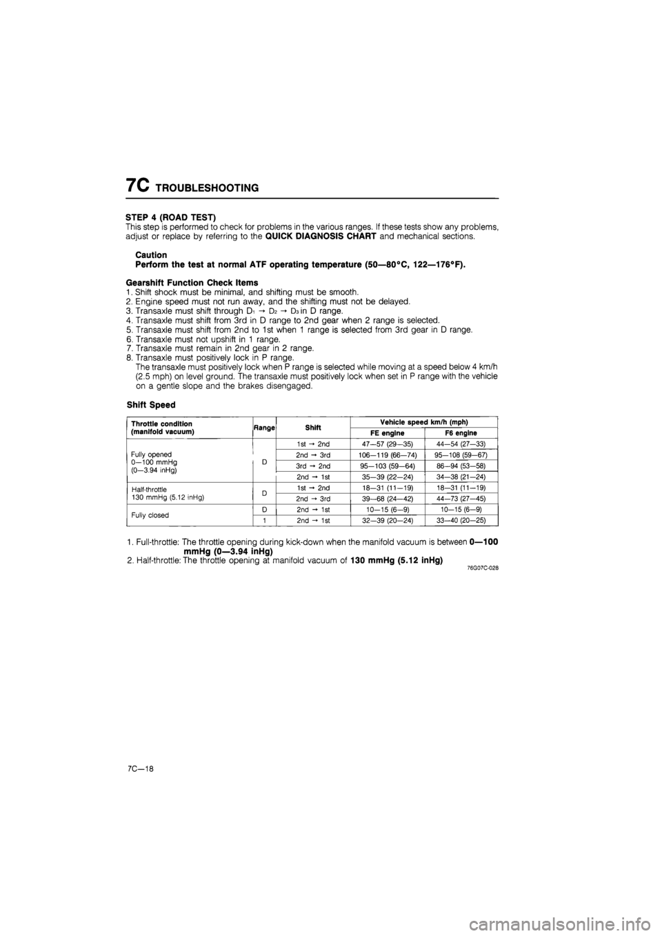
Shift Speed
Throttle condition
(manifold vacuum) Hange Shift Vehicle speed km/h (mph) Throttle condition
(manifold vacuum) Hange Shift FE engine F6 engine
Fully opened 0—100 mmHg (0-3.94 inHg)
D
1st - 2nd 47—57 (29—35) 44-54 (27-33)
Fully opened 0—100 mmHg (0-3.94 inHg)
D 2nd - 3rd 106-119 (66—74) 95-108 (59-67) Fully opened 0—100 mmHg (0-3.94 inHg)
D 3rd - 2nd 95-103 (59-64) 86-94 (53-58)
Fully opened 0—100 mmHg (0-3.94 inHg)
D
2nd - 1st 35-39 (22-24) 34-38 (21-24)
Half-throttle 130 mmHg (5.12 inHg) D 1st - 2nd 18-31 (11-19) 18-31 (11-19) Half-throttle 130 mmHg (5.12 inHg) D 2nd -»• 3rd 39-68 (24—42) 44-73 (27-45)
Fully closed D 2nd - 1st 10-15 (6-9) 10-15 (6-9) Fully closed 1 2nd - 1st 32—39 (20-24) 33-40 (20-25)
1. Full-throttle: The throttle opening during kick-down when the manifold vacuum is between 0—100
mmHg (0—3.94 inHg)
2. Half-throttle: The throttle opening at manifold vacuum of 130 mmHg (5.12 inHg) 76G07C-028
7C-18
Page 1139 of 1865
ON-VEHICLE MAINTENANCE 7C
ON-VEHICLE MAINTENANCE
AUTOMATIC TRANSAXLE FLUID (ATF)
Inspection for Fluid Leaks
Check for fluid leaks; the following figure shows the locations where fluid leakage may possibly occur.
1. Kick-down solenoid
2. Vacuum diaphragm
3. Manual shaft
4. Speedometer driven gear
5. Oil level tube
6. Governor cover
7. Governor
8. Oil pan
9. Oil pump
10. Inhibitor switch
11. Transaxle case
12. Oil pump
13. Square head plugs
14. Bearing cover
15. Drive shaft
76G07C-041
©
i
©
[JdQ©
I
Inspection of Level
1. Apply the parking brake and block the wheels to
prevent the vehicle from rolling.
Note
Place the car on a flat, level surface.
2. Run the engine so that the automatic transaxle fluid
reaches operating temperature.
3. While the engine is idling, shift the select lever from
P to 1 and back again.
4. Let the engine idle.
5.Shift the select lever to P.
76G07C-042
7C-25
Page 1304 of 1865
![MAZDA 626 1987 Workshop Manual
1 0 INSPECTION AND ADJUSTMENT
86U10X023
2WS
To oil pump
Si£r To gear housing
86U10X-024
86U10X-025
Thermometer [50—60°C (122—140°C)]
ii ^
Gauge
Close valve
completely
POWER STEERIN MAZDA 626 1987 Workshop Manual
1 0 INSPECTION AND ADJUSTMENT
86U10X023
2WS
To oil pump
Si£r To gear housing
86U10X-024
86U10X-025
Thermometer [50—60°C (122—140°C)]
ii ^
Gauge
Close valve
completely
POWER STEERIN](/manual-img/28/57059/w960_57059-1303.png)
1 0 INSPECTION AND ADJUSTMENT
86U10X023
2WS
To oil pump
Si£r To gear housing
86U10X-024
86U10X-025
Thermometer [50—60°C (122—140°C)]
ii ^
Gauge
Close valve
completely
POWER STEERING PRESSURE
1. Disconnect the high-pressure hose of the gear
housing side, and attach the SST.
Tightening torque:
39—49 N-m (4.0—5.0 m-kg, 29—36 ft-lb)
2. Bleed air from the system.
3. Open the gauge valve fully, then start the engine
and turn the steering wheel fully left and right to
raise the fluid temperature to 50—60°C
(122—140°F)
4. To measure the fluid pressure generated by the
oil pump, close the gauge valve completely and
increase the engine speed to 1,000—1,500 rpm.
If the fluid pressure is low, replace the oil pump
assembly.
Warning
If the valve is left closed for more than 15 sec-
onds, the fluid temperature will increase ex-
cessively and adversely affect the oil pump.
Oil pump fluid pressure
2WS
7,355—7,846 kPa
(75—80 kg/cm2, 1,066—1,138 psi)
4WS
Front 8,093—8,829 kPa
(82.5—90.0 kg/cm2, 1,173—1,280 psi)
Rear 7,112—7,848 kPa
(72.5—80.0 kg/cm2, 1,031—1,138 psi)
To measure the fluid pressure generated at the
gear housing, first open the gauge valve complete-
ly, increase the engine speed to 1,000—1,500
rpm, and then turn the steering wheel fully to the
left and right.
Warning
If the steering wheel is kept in the fully turned
position for more than 15 seconds, the fluid
temperature will rise excessively.
80U10X-026
10—16