1987 MAZDA 626 fuel pressure
[x] Cancel search: fuel pressurePage 1488 of 1865
1 1 ANTI-LOCK BRAKE SYSTEM (ABS)
t
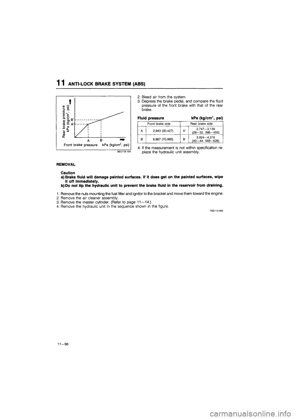
2. Bleed air from the system.
3. Depress the brake pedal, and compare the fluid
pressure of the front brake with that of the rear
brake.
Fluid pressure kPa (kg/cm2, psi)
Front brake side Rear brake side
A 2,943 (30,427)
A'
2,747-3,139
(28-32, 398-455)
A B
B 6,867 (70,995)
B'
3,924-4,316 (40-44, 569-626)
Front brake pressure kPa (kg/cm2, psi) 4. If the measurement is not within specification re-
place the hydraulic unit assembly. 86U11X-194
REMOVAL
Caution
a) Brake fluid will damage painted surfaces. If it does get on the painted surfaces, wipe
it off immediately.
b) Oo not tip the hydraulic unit to prevent the brake fluid in the reservoir from draining.
1. Remove the nuts mounting the fuel filter and ignitor to the bracket and move them toward the engine.
2. Remove the air cleaner assembly.
3. Remove the master cylinder. (Refer to page 11—14.)
4. Remove the hydraulic unit in the sequence shown in the figure.
76G11X-062
11—96
Page 1490 of 1865

1 1 ANTI-LOCK BRAKE SYSTEM (ABS)
INSTALLATION
1. Install in the reverse order of removal.
Before installing the air cleaner assembly, igniter, and fuel filter:
(1) Add brake fluid and bleed air. (Refer to page 11—9.)
(2) Check each part for fluid leakage.
(3) Check the brake fluid level of both the master cylinder reservoir and hydraulic unit reservoir.
2. Tighten all bolts and nuts to the specified torque, referring to torque specifications.
3. After installation:
(1) The sealing reservoir cap (red) is installed on the new hydraulic unit to prevent the brake fluid
from leaking while shipping. Replace it with an original cap (black) after replacing the hydraulic unit.
(2) Check that the hydraulic unit operates properly by testing the pressure reduction. (Refer to page
11-95.)
Torque specifications
11-98
Page 1822 of 1865
30 TECHNICAL DATA
~ ——Engine model
Item —
FE 8-valve
F8 F6
~ ——Engine model
Item —
Middle ECE East General
F8 F6
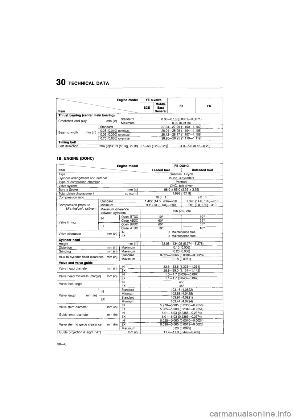
Thrust bearing (center main bearing)
Crankshaft end play
mm
(in) Standard 0.08-0.18 (0.0031-0.0071) Crankshaft end play
mm
(in) Maximum 0.30 (0.0118)
Bearing width
mm (in)
Standard 27.94-27.99 (1.100-1.102)
Bearing width
mm (in)
0.25 (0.010) oversize 28.04—28.09 (1.104-1.106) Bearing width
mm (in)
0.05 (0.020) oversize 28.12-28.17 (1.107-1.109) Bearing width
mm (in)
0.75 (0.030) oversize 28.20—28.25 (1.110—1.112)
Timing belt
Belt deflection
mm
(in)/98
N
(10 kg,
22 lb)
|5.5—6.5 (0.22-0 26) 4.0-5.0 (0.16-0.20)
1B. ENGINE (DOHC)
— Engine model FE DOHC
Item ~ Leaded fuel Unleaded fuel
Type Gasoline, 4-cycle
Cylinder arrangement and number In-line, 4-cylinders
Type
of
combustion chamber Pentroof
Valve system OHC. belt-driven
Bore
x
Stroke mm (in) 86.0
x
86.0 (3.39
x
3.39)
Total piston displacement cc (cu
in)
1,998 (121.9)
Compression ratio 10.0
: 1
9.2
: 1
Standard 1,422 (14.5, 206)—290 1,373 (14.0, 199)—310
Compression pressure Minimum 996 (10.2, 144)—290 961 (9.8, 139)—310
kPa (kg/cm2, psi)-rpm Maximum difference
between cylinders 196 (2.0, 28)
IN Open BTDC 10° 10°
Valve timing
IN Close ABDC 60° 55° Valve timing
EX Open BBDC 60° 55° EX Close ATDC 10° 10°
Valve clearance mm (in) IN 0; Maintenance free Valve clearance mm (in) EX 0; Maintenance free
Cylinder head
Heiaht mm (in) 133.95-134.05 (5.274-5.278)
Distortion mm (in) Maximum 0.15 (0.006)
Grinding mm (in) Maximum 0.20 (0.008)
HLA
to
cylinder head clearance mm (in) Standard 0.025-0.066 (0.0010-0.0026) HLA
to
cylinder head clearance mm (in) Maximum 0.18 (0.0071)
Valve and valve guide
Valve head diameter mm (in) IN 33.6-33.8 (1.323-1.331) Valve head diameter mm (in) EX 28.8-29.0 (1.134—1.142)
Valve head thickness (margin)
mm
(in) IN 1.0-1.7 (0.039-0.067) Valve head thickness (margin)
mm
(in) EX 1.1—1.7 (0.043—0.067)
Valve face angle IN 45° Valve face angle EX 45°
IN Standard 103.18 (4.0622)
Valve length
mm (in)
IN Minimum 102.68 (4.0425) Valve length
mm (in)
EX Standard 103.94 (4.0921) EX Minimum 103.44 (4.0724)
Valve stem diameter mm (in) IN 5.970-5.985 (0.2350-0.2356) Valve stem diameter mm (in) EX 5.965-5.980 (0.2348—0.2354)
Guide inner diameter mm (in) IN 6.01-6.03 (0.2366-0.2374) Guide inner diameter mm (in) EX 6.01—6.03 (0.2366-0.2374)
IN 0.025-0.060 (0.0010-0.0024)
Valve stem
to
guide clearance mm (in) EX 0.030-0.065 (0.0012-0.0026)
Maximum 0.20 (0.0079)
| Guide projection (Height "A") mm (in) 11.4-11.9 (0.449-0.469)
30-8
Page 1832 of 1865
30 TECHNICAL DATA
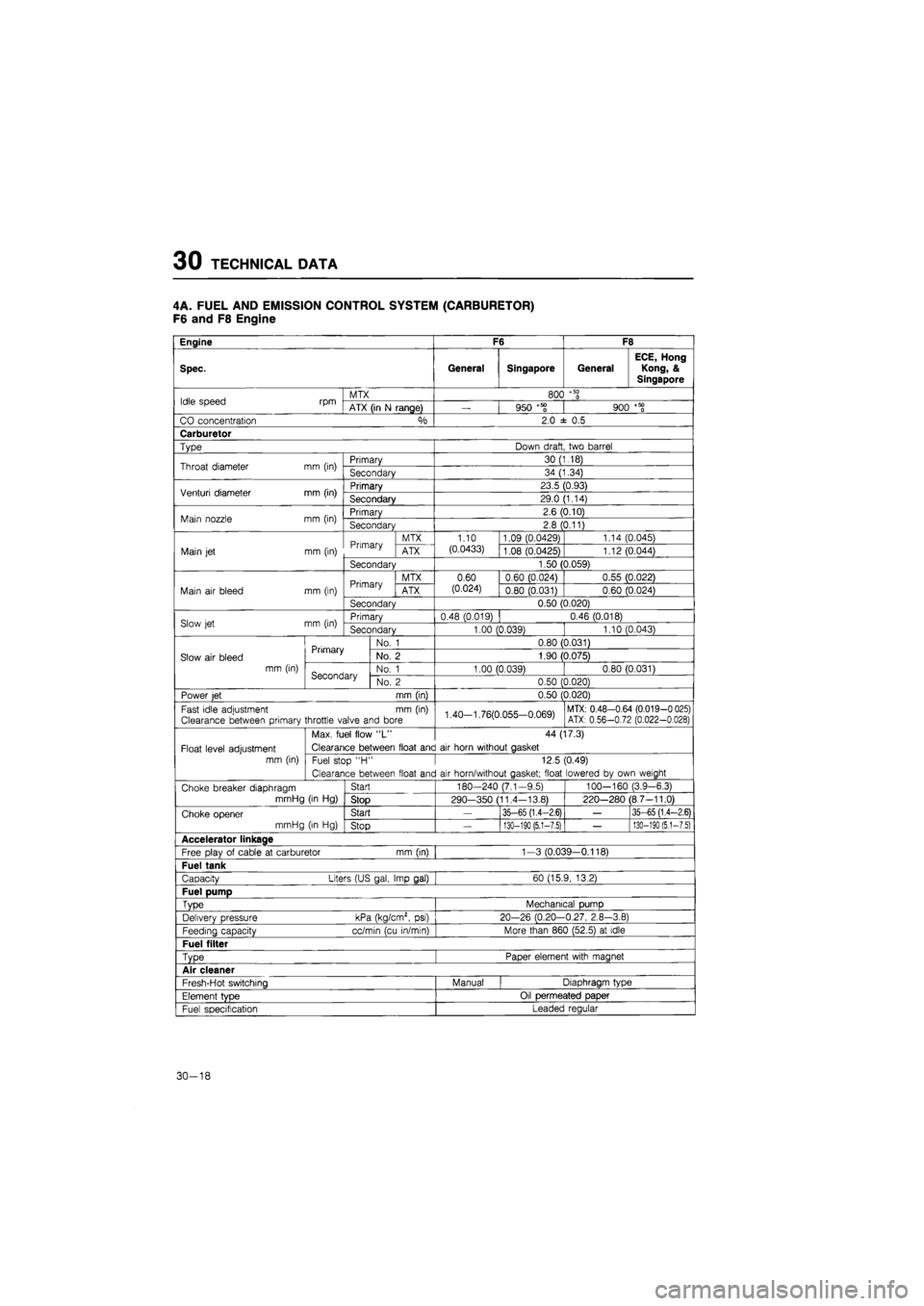
4A. FUEL AND EMISSION CONTROL SYSTEM (CARBURETOR)
F6 and F8 Engine
Engine F6 F8
Spec. General Singapore General
ECE, Hong
Kong, &
Singapore
Idle speed rpm MTX 800
+ 50
0 Idle speed rpm ATX (in
N
range)
—
950 +58 900
+ 50
0
CO concentration °/o 2.0
± 0.5
Carburetor
Type Down draft two barrel
Throat diameter mm (in) Primary 30 (1.18) Throat diameter mm (in) Secondary 34 (1.34)
Venturi diameter mm (in) Primary 23.5 (0.93) Venturi diameter mm (in) Secondary 29.0 (1.14)
Main nozzle mm (in) Primary 2.6 (0.10) Main nozzle mm (in) Secondary 2.8 (0.11)
Primary MTX 1.10 1.09 (0.0429) 1.14 (0.045)
Main
jet
mm (in) Primary ATX (0.0433) 1.08 (0.0425) 1.12 (0.044)
Secondary 1.50 (0.059)
Primary MTX 0.60 0.60 (0.024) 0.55 (0.022)
Main
air
bleed mm (in) Primary ATX (0.024) 0.80 (0.031) 0.60 (0.024)
Secondary 0.50 (0.020)
Slow
jet
mm (in) Primary 0.48 (0.019) 0.46 (0.018) Slow
jet
mm (in) Secondary 1.00 (0.039) 1.10 (0.043)
Primary No.
1
0.80 (0.031)
Slow
air
bleed Primary No.
2
1.90 (0.075)
mm (in) Secondary No.
1
1.00 (0.039) 0.80 (0.031) Secondary No.
2
0.50 (0.020)
Power
jet
mm (in) 0.50 (0.020)
Fast idle adjustment
mm (in)
Clearance between primary throttle valve and bore 1.40-1.76(0.055-0.069) MTX: 0.48-0.64 (0.019-0 025) ATX: 0.56-0.72 (0.022-0.028)
Max. fuel flow
"L"
44 (17.3)
Float level adjustment Clearance between float and
air
horn without gasket
mm (in) Fuel stop
"H •
12.5 (0.49)
Clearance between float and
air
horn/without gasket; float lowered
by
own weight
Choke breaker diaphragm Start 180-240 (7.1-9.5) 100—160 (3.9-6.3)
mmHg
(in Hg)
Stop 290—350 (11.4-13.8) 220-280 (8.7-11.0)
Choke opener Start
—
35-65 (1.4-2.6)
—
35-65 (1.4-2.6)
mmHg
(in Hg)
Stop
—
130-190 (5.1-7.5)
—
130-190
(5,1-7.5)
Accelerator linkage
Free plav
of
cable
at
carburetor mm (in) 1-3 (0.039—0.118)
Fuel tank
Capacity Liters (US gal, Imp gal) 60 (15.9, 13.2)
Fuel pump
Type Mechanical pump
Delivery pressure kPa (kg/cm2,
psi)
20-26 (0.20-0.27, 2.8-3.8)
Feedina capacity cc/min (cu in/min) More than 860 (52.5)
at
idle
Fuel filter
Type Paper element with magnet
Air cleaner
Fresh-Hot switching Manual Diaphragm type
Element
tvDe
Oil permeated paper
Fuel specification Leaded regular
30-18
Page 1833 of 1865
TECHNICAL DATA 30
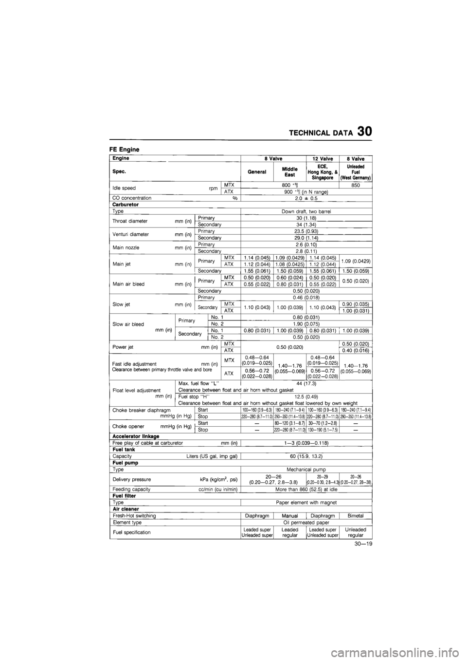
FE Engine
Engine 8 Valve 12 Valve 8 Valve
Spec. General Middle
East
ECE,
Hong Kong, &
Singapore
Unleaded
Fuel
(West Germany)
Idle speed rpm MTX 800
+5§
850 Idle speed rpm ATX 900 +5S
(ir
N range)
CO concentration
%
2.0
± 0,5
Carburetor
Type Down draft, two barrel
Throat diameter mm (in) Primary 30 (1.18) Throat diameter mm (in) Secondary 34 (1.34)
Venturi diameter mm (in) Primary 23.5 (0.93) Venturi diameter mm (in) Secondary 29.0 (1.14)
Main nozzle mm (in) Primary 2.6 (0.10) Main nozzle mm (in) Secondary 2.8 (0.11)
Primary MTX 1.14 (0.045) 1.09 (0.0429) 1.14 (0.045) 1.09 (0.0429) Main
jet
mm (in) Primary ATX 1.12 (0.044) 1.08 (0.0425) 1.12 (0.044) 1.09 (0.0429)
Secondary 1.55 (0.061) 1.50 (0.059) 1.55 (0.061) 1.50 (0.059)
Primary MTX 0.50 (0.020) 0.60 (0.024) 0.50 (0.020) 0.50 (0.020) Main
air
bleed mm (in) Primary ATX 0.55 (0.022) 0.80 (0.031) 0.55 (0.022) 0.50 (0.020)
Secondary 0.50 (0.020)
Primary 0.46 (0.018)
Slow jet mm (in) Secondary MTX 1.10 (0.043) 1.00 (0.039) 1.10 (0.043) 0.90 (0.035) Secondary ATX 1.10 (0.043) 1.00 (0.039) 1.10 (0.043) 1.00 (0.031)
Primary No.
1
0.80 (0.031)
Slow
air
bleed Primary No.
2
1.90 (0.075)
mm (in) Secondary No.
1
0.80 (0.031) 1.00 (0.039) 0.80 (0.031) 1.00 (0.039) Secondary No.
2
0.50 (0.020)
Power jet mm (in) MTX 0.50 (0.020) 0.50 (0.020) Power jet mm (in) ATX 0.50 (0.020) 0.40 (0.016)
Fast idle adjustment mm (in) MTX 0.48-0.64 (0.019-0.025) 1 40—1
76
0.48-0.64 (0.019-0.025) 1
40
1
76
Clearance between primary throttle valve and bore ATX 0.56-0.72
(0.022-0.028) (0.055-0.069) 0.56-0.72 (0.022-0.028) (0.055-0.069)
Max. fuel flow
"L"
44 (17.3)
Float level adjustment Clearance between float and
air
horn without aasket
mm (in) Fuel stop
"H •
12.5 (0.49)
Clearance between float and
air
horn without aasket float lowered
bv
own weiaht
Choke breaker diaphragm Start
100-160 (3,9-6.3) 180-240 (7.1-94) 100-160 (39-6.3) 180-240 (7.1-9,4)
mmHg
(in Hg)
Stop
220-280 (8.7-11,0) 290-350 (11,4-13.8) 220-280 (8.7-11.0) 290-350 (11.4-13.8)
Choke opener mmHg (in
Hg)
Start
—
80-120 (3.1-8.7) 30-70 (1.2-2.8)
—
Choke opener mmHg (in
Hg)
Stop
—
220-280 (87-11.0) 130-190 (5.1-7.5)
—
Accelerator llnkaae
Free play
of
cable
at
carburetor mm (in) 1-3 (0.039-0.118)
Fuel tank
Capacity Liters (US gal, Imp gal) 60 (15.9, 13.2)
Fuel pump
TvDe
Mechanical pump
Delivery pressure kPa (kg/cm2,
psi)
20-26 (0.20-0.27, 2.8-3.8)
20-29 (0.20-030, 2.8-4.3) 20-26
(020-0.27, 28-38)
Feeding capacity cc/min (cu in/min) More than 860 (52.5)
at
idle
Fuel filter
TvDe
Paoer element with maanet
Air cleaner
Fresh-Hot switchina Diaohraam Manual Diaohraam Bimetal
Element tvoe Oil oermeated oaoer
Fuel specification Leaded super Unleaded super Leaded regular Leaded super Unleaded super Unleaded regular
30-19
Page 1834 of 1865
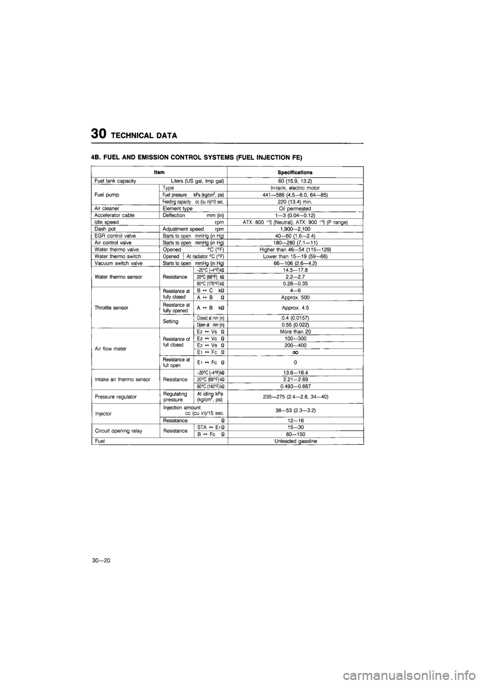
30 TECHNICAL DATA
4B. FUEL AND EMISSION CONTROL SYSTEMS (FUEL INJECTION FE)
Item Specifications
Fuel tank capacity Liters (US gal, Imp gal) 60 (15.9, 13.2)
Fuel pump
Type In-tank, electric motor
Fuel pump Fuel pressure kPa (kg/cm2, psi) 441-588 (4.5-6.0, 64-85) Fuel pump
Feeding capacity cc (cu in)/10 sec. 220 (13.4) min.
Air cleaner Element type Oil permeated
Accelerator cable Deflection
mm
(in) 1—3 (0.04-0.12)
Idle speed
rpm
ATX: 800 +58 (Neutral), ATX: 900 +600
(P
range)
Dash
pot
Adjustment speed
rpm
1,900-2.100
EGR control valve Starts
to
open mmHg (in Hg) 40-60 (1.6-2.4)
Air control valve Starts
to
open mmHg (in Hg) 180-280 (7.1-11)
Water thermo valve Opened
°C
(°F) Higher than 46—54 (115-129)
Water thermo switch Opened
At
radiator
°C
(°F) Lower than 15—19 (59—66)
Vacuum switch valve Starts to open mmHg (in Hg) 66—106 (2.6—4.2)
Water thermo sensor Resistance
-20°C (-4°F)k!) 14.5-17.8
Water thermo sensor Resistance 20°C (68°F)
kQ
2.2-2.7 Water thermo sensor Resistance
80°C (176°F)k!i 0.28-0.35
Throttle sensor
Resistance
at
fully closed
B
C kQ
4-6
Throttle sensor
Resistance
at
fully closed A
« B Q
Approx.
500
Throttle sensor Resistance
at
fully opened A
«• B kQ
Approx.
4.5
Throttle sensor
Setting Closed at mm (in) 0.4 (0.0157)
Throttle sensor
Setting Open at mm (in) 0.55 (0.022)
Air flow meter
Resistance
of
full closed
E2 « Vs fi
More than
20
Air flow meter
Resistance
of
full closed
E2 •+ Vc 0
100-300
Air flow meter
Resistance
of
full closed
E2 VB Q
200-400 Air flow meter
Resistance
of
full closed
Ei
•+ Fc Q OO
Air flow meter
Resistance
at
full open Ei
•+ Fc Q
0
Intake
air
thermo sensor Resistance
-20°C M°RkQ 13.6-18.4
Intake
air
thermo sensor Resistance 20°C (68°F) kfi 2.21—2.69 Intake
air
thermo sensor Resistance
60°C (140°RkQ 0.493-0.667
Pressure regulator Regulating pressure At idling kPa
(kg/cm
,
psi) 235-275 (2.4—2.8, 34-40)
Injector
Injection amount cc (cu in)/15 sec. 38-53 (2.3-3.2) Injector
Resistance
Q
12-16
Circuit opening relay Resistance STA Ei Q 15-30 Circuit opening relay Resistance B
Fc fi
80-150
Fuel Unleaded gasoline
30-20
Page 1835 of 1865
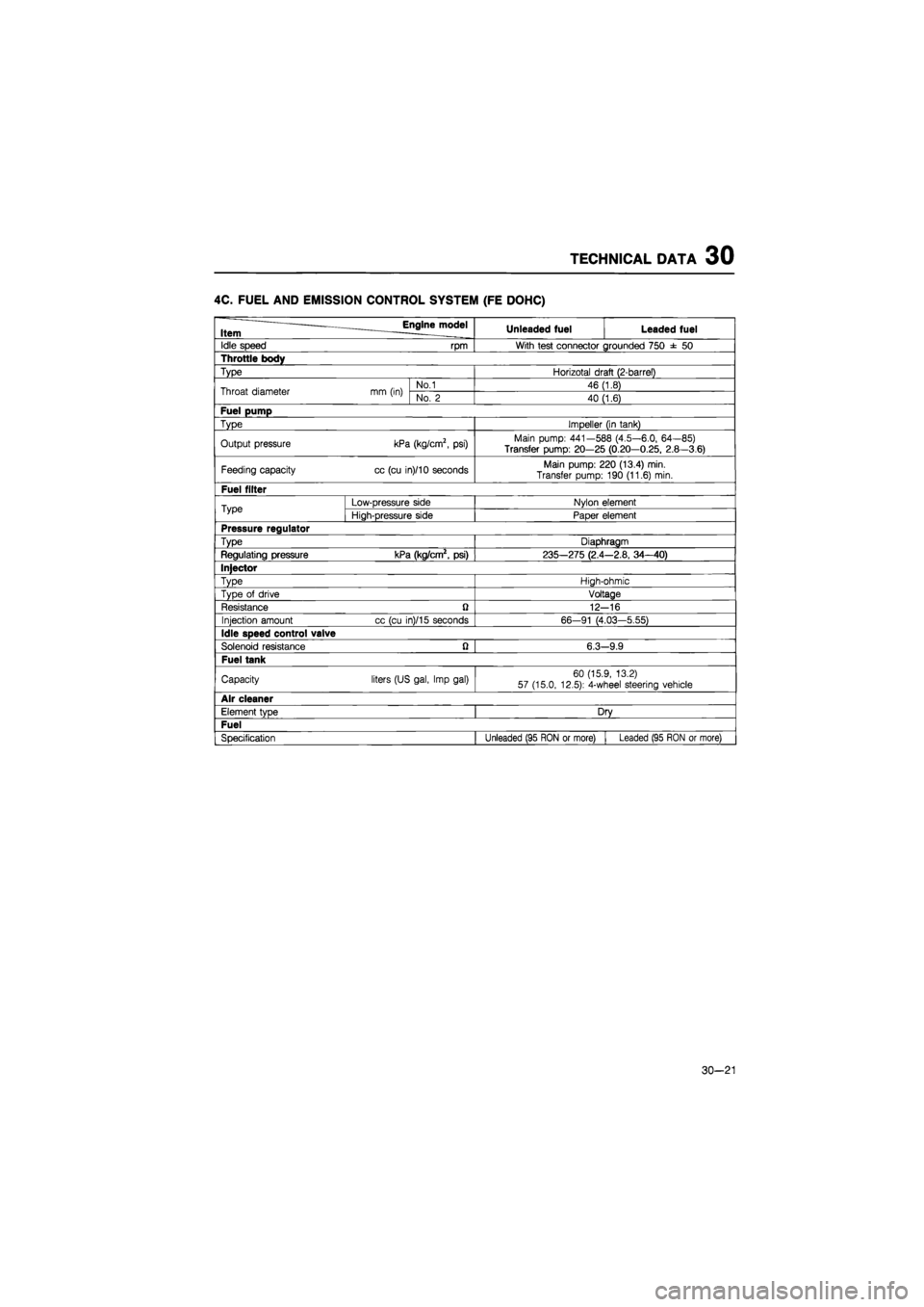
TECHNICAL DATA 30
4C. FUEL AND EMISSION CONTROL SYSTEM (FE DOHC)
Item ^Engine^model Unleaded fuel Leaded fuel
Idle speed rpm With test connector grounded 750
± 50
Throttle body
Type Horizotal draft (2-barrel)
Throat diameter mm (in) No.1 46 (1.8) Throat diameter mm (in) No.
2
40 (1.6)
Fuel pump
Type Impeller (in tank)
Output pressure kPa (kg/cm2,
psi)
Main pump: 441—588 (4.5—6.0, 64—85)
Transfer pump: 20—25 (0.20—0.25, 2.8—3.6)
Feeding capacity cc (cu in)/10 seconds Main pump: 220 (13.4) min. Transfer pump: 190 (11.6) min.
Fuel filter
Type Low-pressure side Nylon element Type High-pressure side Paper element
Pressure regulator
Type Diaphragm
Regulating pressure kPa (kg/cm2, psi) 235-275 (2.4 -2.8, 34-40)
Injector
Type High-ohmic
Type
of
drive Voltage
Resistance
ft
12--16
Injection amount cc (cu in)/15 seconds 66-91 (4.03-5.55)
Idle speed control valve
Solenoid resistance Q 6.3--9.9
Fuel tank
Capacity liters (US gal, Imp gal) 60 (15.9, 13.2) 57 (15.0, 12.5): 4-wheel steering vehicle
Air cleaner
Element type Dry
Fuel
Specification Unleaded (95 RON
or
more) i Leaded (95 RON
or
more)
30-21
Page 1836 of 1865
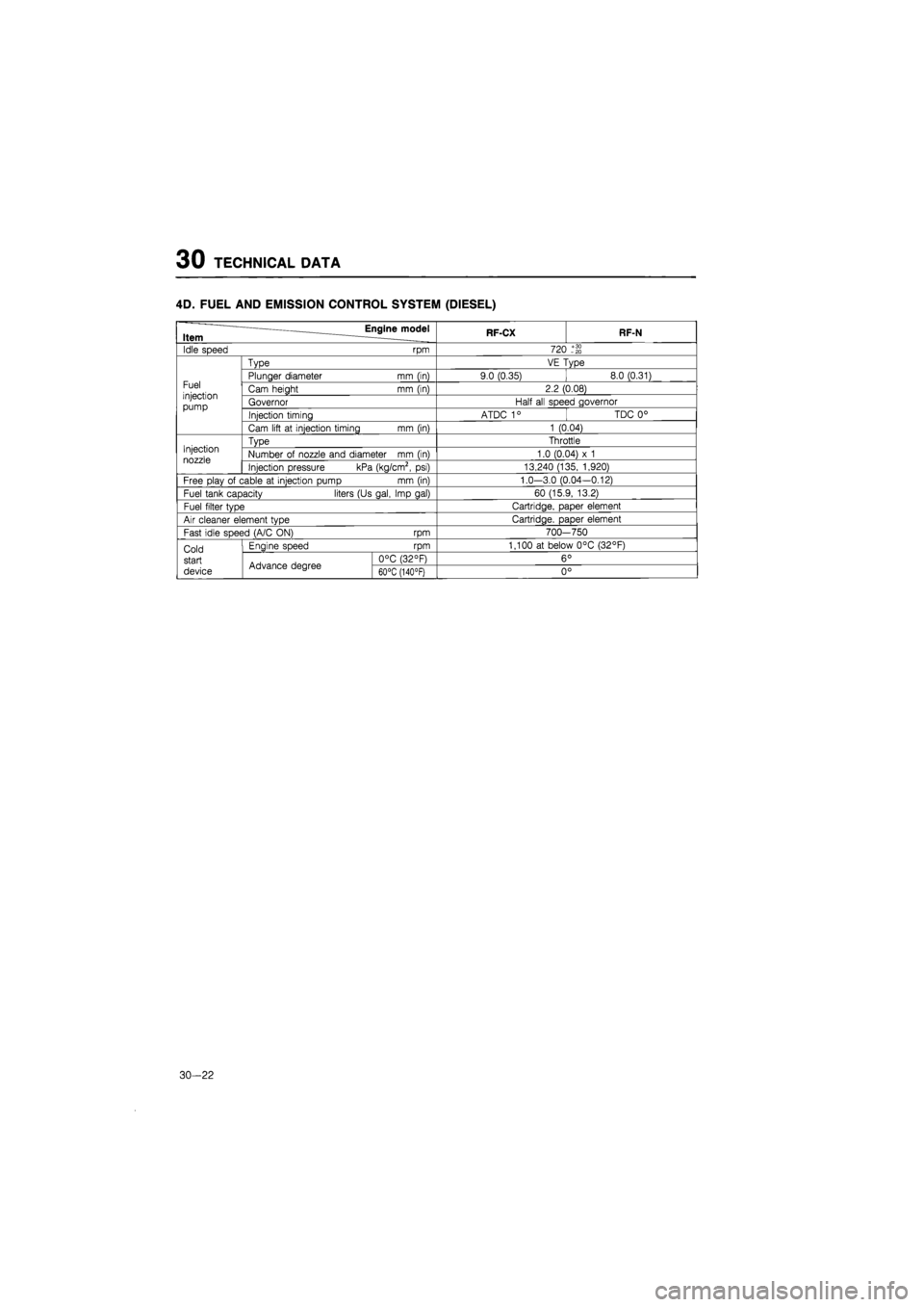
30 TECHNICAL DATA
4D. FUEL AND EMISSION CONTROL SYSTEM (DIESEL)
Item — Engine model RF-CX RF-N
Idle speed rpm 720 -20
Type VE Type
Fuel injection pump
Plunger diameter mm (in) 9.0 (0.35) 8.0 (0.31) Fuel injection pump
Cam height mm (in) 2.2 (0.08) Fuel injection pump Governor Half
all
speed governor
Fuel injection pump Injection timing ATDC 1
°
TDC
0°
Cam lift
at
injection timing mm (in) 1 (0.04)
Injection
nozzle
Type Throttle Injection
nozzle Number
of
nozzle and diameter
mm (in)
1.0 (0.04)
x 1
Injection
nozzle Injection pressure kPa (kg/cm2,
psi)
13,240 (135, 1,920)
Free play
of
cable
at
injection pump mm (in) 1.0-3.0 (0.04-0.12)
Fuel tank capacity liters (Us gal, Imp gal) 60 (15.9, 13.2)
Fuel filter type Cartridge, paper element
Air cleaner element type Cartridge, paper element
Fast idle speed (A/C ON) rpm 700--750
Cold Engine speed rpm 1,100
at
below 0°C (32°F)
start Advance degree 0°C (32°F) 6 0
device Advance degree 60°C (140°F) 0
°
30—; 22