Page 620 of 1865

FUEL SYSTEM 4C
5. Connect the SST to the battery and injector.
6. Check the injection volume with a graduated con-
tainer.
Injection volume:
Approx. 66—91 cc (4.03—5.55 cu in) /15 sec.
Caution
When using the SST, make sure of the SST
number and use correct one.
7. If not correct, replace the injector.
76G04C-107
Rear seat Cushion Release Button -
76G04C-108
TRANSFER PUMP CONTROL SYSTEM (4 WHEEL
STEERING)
1. Remove the rear seat. (Refer to 14 section.)
2. Remove the fuel filler cap.
3. Turn the ignition switch ON.
Note
a) The tank should be more than 1/3 full.
b) Due to the delay timer, transfer pump oper-
ation begins approx. 10 sec. after the igni-
tion switch is turned ON.
4. Listen for the operational sound of the transfer
pump.
5. Install the fuel filler cap.
6. If no sound was heard, check the voltage at the
transfer pump connector.
Terminal (wire) Voltage
A, C (WG) Approx. 12V
I, J (B) OV
86U04B-075
I C A
lb d
cp a • • •
J
76G04C-211
7. If the voltages are correct, replace the transfer
pump.
8. If not correct, disconnect the transfer pump con-
nector.
9. Check the voltage at the terminals below.
Terminal (wire) Voltage
A, C (WG) Approx. 12V
I, J (B) OV
10. If the voltages are correct, replace the transfer
pump.
4C—59
Page 662 of 1865

CONTROL SYSTEM 4C
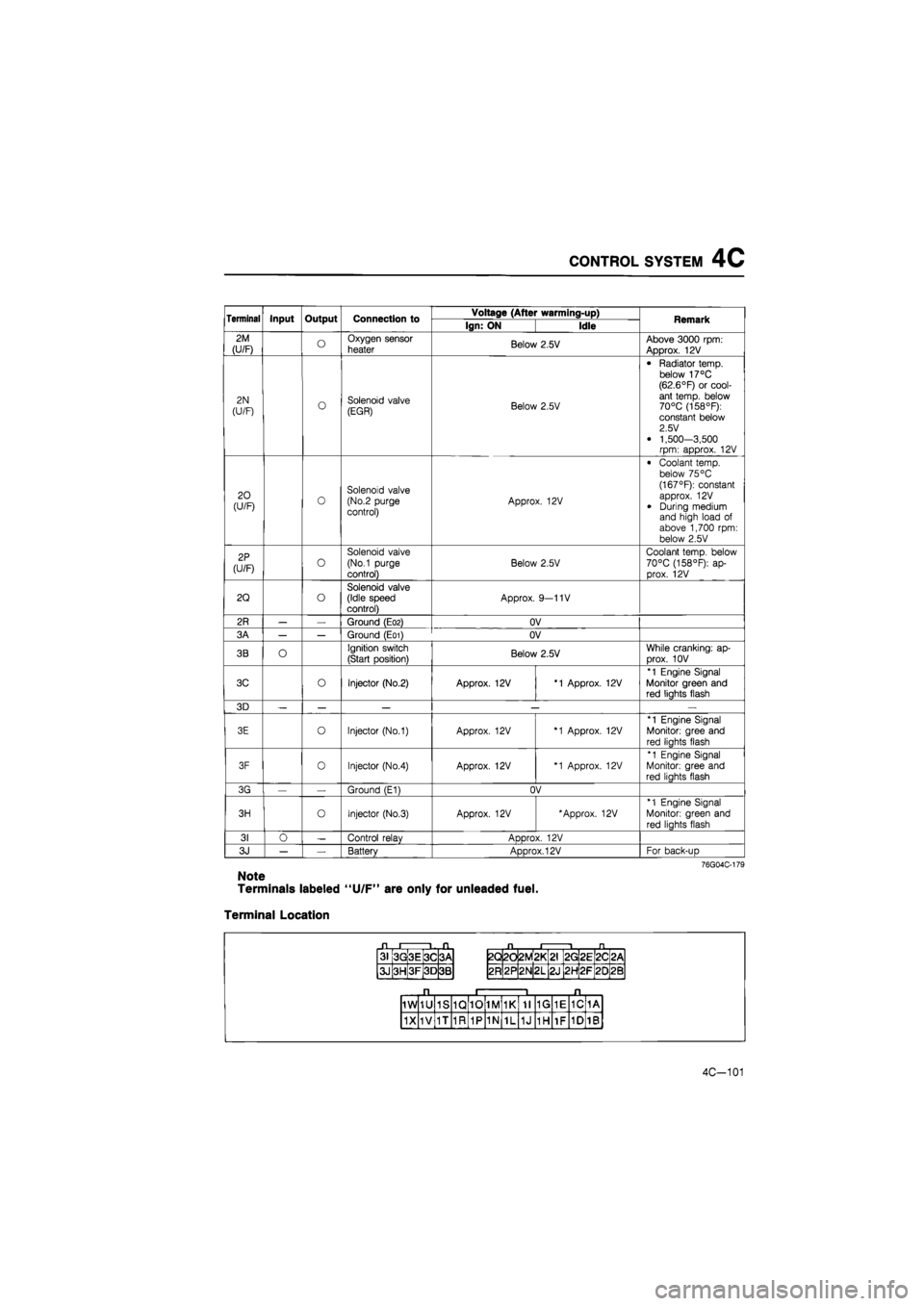
Terminal Input Output Connection to Voltage (After warming-up) Remark Terminal Input Output Connection to Ign: ON Idle Remark
2M
(U/F) o Oxygen sensor
heater Below 2.5V Above 3000 rpm: Approx. 12V
2N
(U/F) o Solenoid valve (EGR) Below 2.5V
• Radiator temp, below 17°C (62.6°F) or cool-ant temp, below 70°C (158°F): constant below 2.5 V
• 1,500-3,500 rpm: approx. 12V
20 (U/F) 0 Solenoid valve (No.2 purge control) Approx. 12V
• Coolant temp, below 75 °C (167°F): constant approx. 12V
• During medium and high load of above 1,700 rpm: below 2.5V
2P
(U/F) o
Solenoid valve
(No.1 purge
control)
Below 2.5V
Coolant temp, below 70°C (158°F): ap-prox. 12V
2Q o Solenoid valve (Idle speed control) Approx. 9—11V
2R — — Ground (E02) OV
3A — — Ground (E01) OV
3B O Ignition switch
(Start position) Below 2.5V While cranking: ap-
Drox. 10V
3C o Injector (No.2) Approx. 12V *1 Approx. 12V
*1 Engine Signal Monitor green and red liahts flash
3D — — — — —
3E o Injector (No.1) Approx. 12V *1 Approx. 12V
*1 Engine Signal
Monitor: gree and
red liahts flash
3F 0 Injector (No.4) Approx. 12V *1 Approx. 12V
*1 Engine Signal Monitor: gree and red liahts flash
3G — Ground (E1) OV
3H o Injector (No.3) Approx. 12V 'Approx. 12V *1 Engine Signal
Monitor: green and
red lights flash
31 0 — Control relav ADDrox. 12V
3J — — Battery Approx. 12V For back-uD
76G04C-179
Note
Terminals labeled "U/F" are only for unleaded fuel.
Terminal Location
31 3G 3E 3C 3A
3J 3H 3F 3D 3B
2Q 2d 2M *
L
CM
2G 2E 2C <
CM
2R 2P 2N 2L 2J 2H 2F 20 2B
1W 1U 1S 1Q 10 1M 1K 11 1G 1E 1C 1A
1X 1V 1T 1R 1P 1N 1L 1J 1H 1F 1D 1B
4C-101
Page 665 of 1865

4C CONTROL SYSTEM
Jjf (Terminal A)
n PI
WRED r^j
BLACK
BLACK 1 (Terminal C)
76G04C-189
Replacement
1. Disconnect the connector.
2. Loosen the air hose clamps.
3. Replace the air flow sensor.
Caution
Install the air flow sensor so that the arrow on
the sensor aligns with air flow direction.
4. Tighten the hose clamps.
5. Reconnect the connector to the sensor.
THROTTLE SENSOR
Caution
Use a precision voltmeter with a scale of 0.01V
to inspect or adjust the throttle sensor. If it
is not available, replace the throttle sensor
and throttle body as an assembly.
Inspection
1. Disconnect the throttle sensor connector (3-pin).
2. Connect the SST between the throttle sensor and
the wiring harness.
3. Turn the ignition switch ON.
4. Measure BLACK and RED wire voltages.
Specifications:
BLACK—Approx. OV
RED—4.5—5.5V
5. If not correct, check the battery voltage and wir-
ing harness. If these are OK, replace the engine
control unit.
6. Using the RED wire voltage as a guide, find the
specified BLUE wire voltage ranges in the table.
RED wire voltage
Specified range (V) RED wire voltage Fully close Fully open
4.90—4.99V 0.40-0.58 3.90-4.60
5.00—5.09V 0.41—0.60 3.97-4.70
5.10-5.19V 0.42—0.61 4.05—4.79
4C-104
Page 666 of 1865
CONTROL SYSTEM 4C
7. Make sure that the throttle valve is fully closed.
8. Check that the BLUE wire voltage is within the
specified range.
9. Adjust the throttle sensor if necessary
76g04c-191
10. Open the throttle valve fully.
11. Check that BLUE wire voltage is within the speci-
fied range.
12. If not correct, replace the throttle sensor.
76g04c-192
13. Turn the ignition switch OFF.
14. Disconnect the SST and reconnect the throttle sen-
sor connector.
15. Disconnect the negative battery terminal and de-
press the brake pedal for 5 seconds to eliminate
the malfunction memory from the control unit.
76g04c-193
Adjustment
1. Perform steps 1 to 7 in the inspection procedure.
2. Connect the voltmeter to the BLUE wire.
3. Loosen the throttle sensor mounting screw.
76G04C-194
4C-105
Page 667 of 1865

4C CONTROL SYSTEM
4. Make sure that the throttle valve is fully closed.
5. Turn the throttle sensor so that the BLUE wire volt-
age indicates within the specified closed range.
6. Tighten the throttle sensor mounting screw.
7. Recheck that the BLUE wire voltage is within the
specified range.
76G04C-195
8. Turn the ignition switch OFF.
9. Disconnect the SST and reconnect the throttle sen-
sor connector.
10. Disconnect the negative battery terminal and de-
press the brake pedal for 5 seconds to eliminate
the from the malfunction memory from the control
unit.
76G04C-196
76G04C-198
4C-106
IDLE SWITCH
Inspection
1. Disconnect the idle switch connector.
2. Check continuity between the switch and a ground.
Throttle valve condition Continuity
Fully closed Yes
Open No
3. If not correct, check condition of the wiring harness
of the idle switch. Replace the idle switch and throt-
tle body as an assembly, if necessary.
WATER THERMO SWITCH
Inspection
1. Remove the switch from the radiator.
2. Place the switch in water with a thermometer and
heat the water gradually.
3. Check for continuity of the switch with an
ohmmeter.
Coolant temp. Continuity
More than approx. 17°C (63°F) Yes
Less than approx. 10°C (63°F) No
4. If not correct, replace the water thermo switch.
Page 676 of 1865

ON-VEHICLE MAINTENANCE 4D
INJECTION TIMING
1. Disconnect the negative battery cable.
2. Release the CSD using the screw driver.
3. Remove the cover on the clutch housing.
4. Turn the flywheel and set the indicator at TDC.
5. Disconnect the injection pipes from the injection
pump.
76G04D-008
6. Remove the hydraulic head plug from the injec-
tion pump.
7. Mount the SST into the plug hole on the hydraulic
head so the tip of the dial gauge pointer touches
the plunger end of the pump and the dial gauge
indicates approx. 2.0 mm (0.08 in).
76.G04D-009
8. Turn the crankshaft slowly counterclockwise to
30—50° BTDC.
9. Make sure the dial indicator pointer no longer
moves by slightly turning the crankshaft.
10. Set the dial gauge scale to Zero at the pointer.
76G04D-010
11. Turn the crankshaft clockwise to align the indica-
tor pin at ATDC 1° (RF-CX), TDC 0° (RF-N).
12. Read the dial gauge.
Cam lift: 0.98—1.02 mm (0.038—0.040 in)
13. If not within the specification, adjust the injection
timing. (Refer to page 4D—24.)
76G04D-011
4D-5
Page 687 of 1865
4D SUPERCHARGING SYSTEM (RF-CX)
INTERCOOLER
Removal and Installation
1. Remove in the sequence shown in the figure.
2. Install in the reverse order of removal.
3. Check for air leakage.
76G04D-037
5. Front bumper (Refer to Section 14.)
6. Cooling fan
7. Air pipe
8. Intercooler
Inspection
Check the intercooler for cracks or damage. Replace
if necessary.
8—11 N-m (80—110 cm-kg, 69—95 In-lb)
1. Battery
2. Battery carrier
3. Front grille (Refer to Section 14.)
4. Headlight (Refer to Section 14.)
76G04D-038
4D—16
Page 707 of 1865

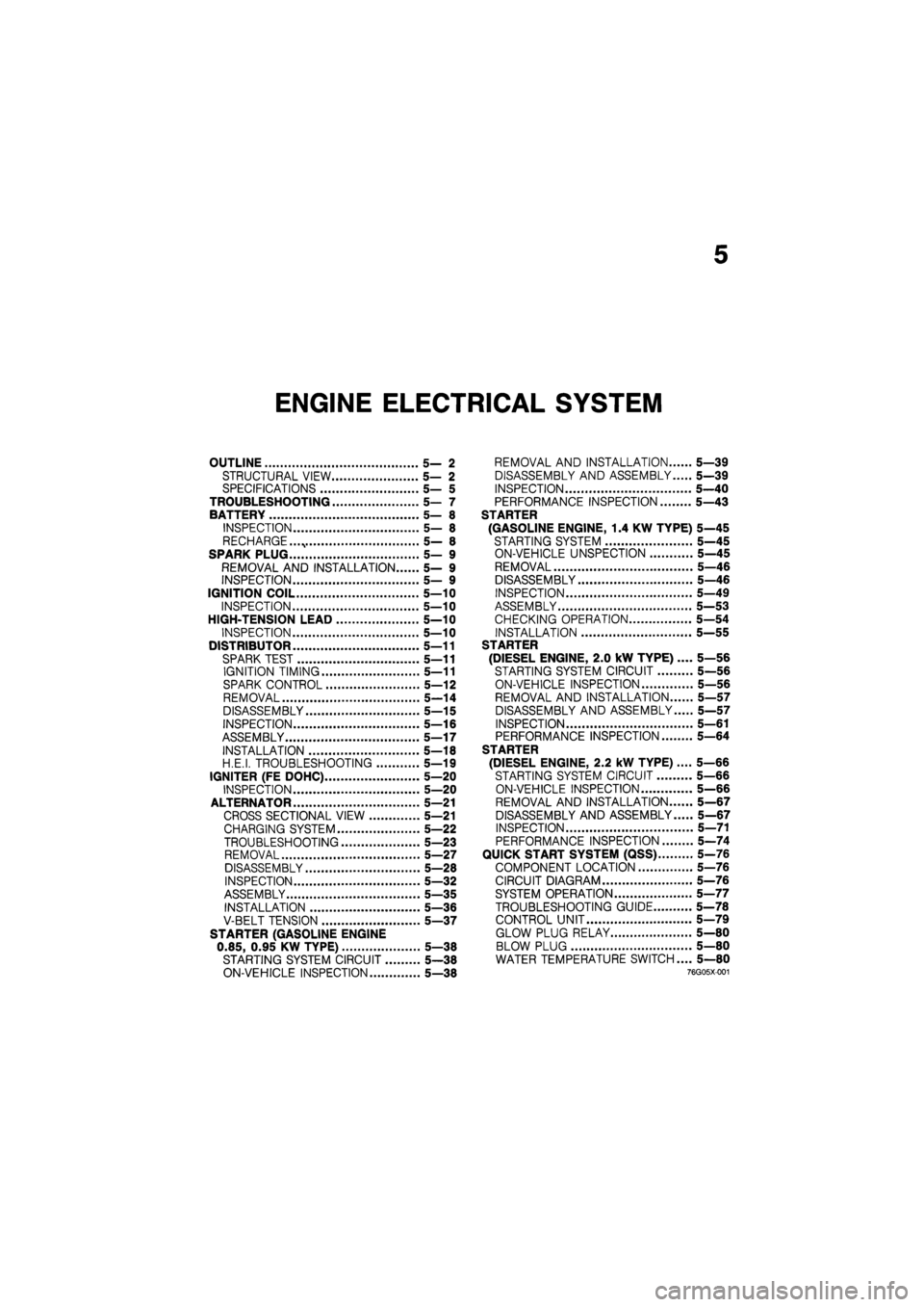
5
ENGINE ELECTRICAL SYSTEM
OUTLINE 5— 2
STRUCTURAL VIEW 5— 2
SPECIFICATIONS 5— 5
TROUBLESHOOTING 5— 7
BATTERY 5— 8
INSPECTION 5— 8
RECHARGE. 5— 8
SPARK PLUG 5— 9
REMOVAL AND INSTALLATION 5— 9
INSPECTION 5— 9
IGNITION COIL 5—10
INSPECTION 5—10
HIGH-TENSION LEAD 5—10
INSPECTION 5—10
DISTRIBUTOR 5—11
SPARK TEST 5—11
IGNITION TIMING 5—11
SPARK CONTROL 5—12
REMOVAL 5—14
DISASSEMBLY 5—15
INSPECTION 5—16
ASSEMBLY 5—17
INSTALLATION 5—18
H.E.I. TROUBLESHOOTING 5—19
IGNITER (FE DOHC) 5—20
INSPECTION 5—20
ALTERNATOR 5—21
CROSS SECTIONAL VIEW 5—21
CHARGING SYSTEM 5—22
TROUBLESHOOTING 5—23
REMOVAL 5—27
DISASSEMBLY 5—28
INSPECTION 5—32
ASSEMBLY 5—35
INSTALLATION 5—36
V-BELT TENSION 5—37
STARTER (GASOLINE ENGINE
0.85, 0.95 KW TYPE) 5—38
STARTING SYSTEM CIRCUIT 5—38
ON-VEHICLE INSPECTION 5—38
REMOVAL AND INSTALLATION 5—39
DISASSEMBLY AND ASSEMBLY 5—39
INSPECTION 5—40
PERFORMANCE INSPECTION 5—43
STARTER
(GASOLINE ENGINE, 1.4 KW TYPE) 5—45
STARTING SYSTEM 5—45
ON-VEHICLE UNSPECTION 5—45
REMOVAL 5—46
DISASSEMBLY 5—46
INSPECTION 5—49
ASSEMBLY 5—53
CHECKING OPERATION 5—54
INSTALLATION 5—55
STARTER
(DIESEL ENGINE, 2.0 kW TYPE) .... 5—56
STARTING SYSTEM CIRCUIT 5—56
ON-VEHICLE INSPECTION 5—56
REMOVAL AND INSTALLATION 5—57
DISASSEMBLY AND ASSEMBLY 5—57
INSPECTION 5—61
PERFORMANCE INSPECTION 5—64
STARTER
(DIESEL ENGINE, 2.2 kW TYPE).... 5—66
STARTING SYSTEM CIRCUIT 5—66
ON-VEHICLE INSPECTION 5—66
REMOVAL AND INSTALLATION 5—67
DISASSEMBLY AND ASSEMBLY 5—67
INSPECTION 5—71
PERFORMANCE INSPECTION 5—74
QUICK START SYSTEM (QSS) 5-76
COMPONENT LOCATION 5—76
CIRCUIT DIAGRAM 5—76
SYSTEM OPERATION 5—77
TROUBLESHOOTING GUIDE 5—78
CONTROL UNIT 5—79
GLOW PLUG RELAY 5—80
BLOW PLUG 5—80
WATER TEMPERATURE SWITCH.... 5—80
76g05x-001