Page 581 of 878
2. INSTALL IDLER PULLEY
(See step 2 in timing belt installation in Engine Mechani-
cal)
3. 2JZ±GTE:
INSTALL WATER OUTLET AND NO.1 WATER BYPASS
PIPE
(a) Install 2 new O±rings to the No.1 water bypass pipe.
(b) Apply soapy water to the O±rings.
(c) Install the No.1 water pass pipe to the water pump.
(d) Install a new gasket and the water outlet with the 2 bolts.
Torque: 21 NVm (210 kgfVcm, 15 ftVlbf)
(e) Connect the ECT sensor and sender gauge connectors.
4. 2JZ±GE:
INSTALL WATER BYPASS OUTLET AND NO.1 WATER
BYPASS PIPE
(a) Install 2 new O±rings to the No.1 water bypass pipe.
(b) Install a new O±ring and the water bypass outlet with the 2
bolts.
Torque: 8.8 NVm (90 kgfVcm, 78 in.Vlbf)
5. 2JZ±GTE:
CONNECT TURBO WATER HOSES TO WATER OUTLET
6. 2JZ±GE Except California:
INSTALL EXHAUST MANIFOLD HEAT INSULATOR
7. 2JZ±GTE:
INSTALL GENERATOR
(See generator installation in Charging System)
8. INSTALL TIMING BELT
(See steps 10 to 14 in timing belt installation in Engine
Mechanical)
9. INSTALL WATER INLET AND LOWER RADIATOR HOSE
ASSEMBLY
(See thermostat installation)
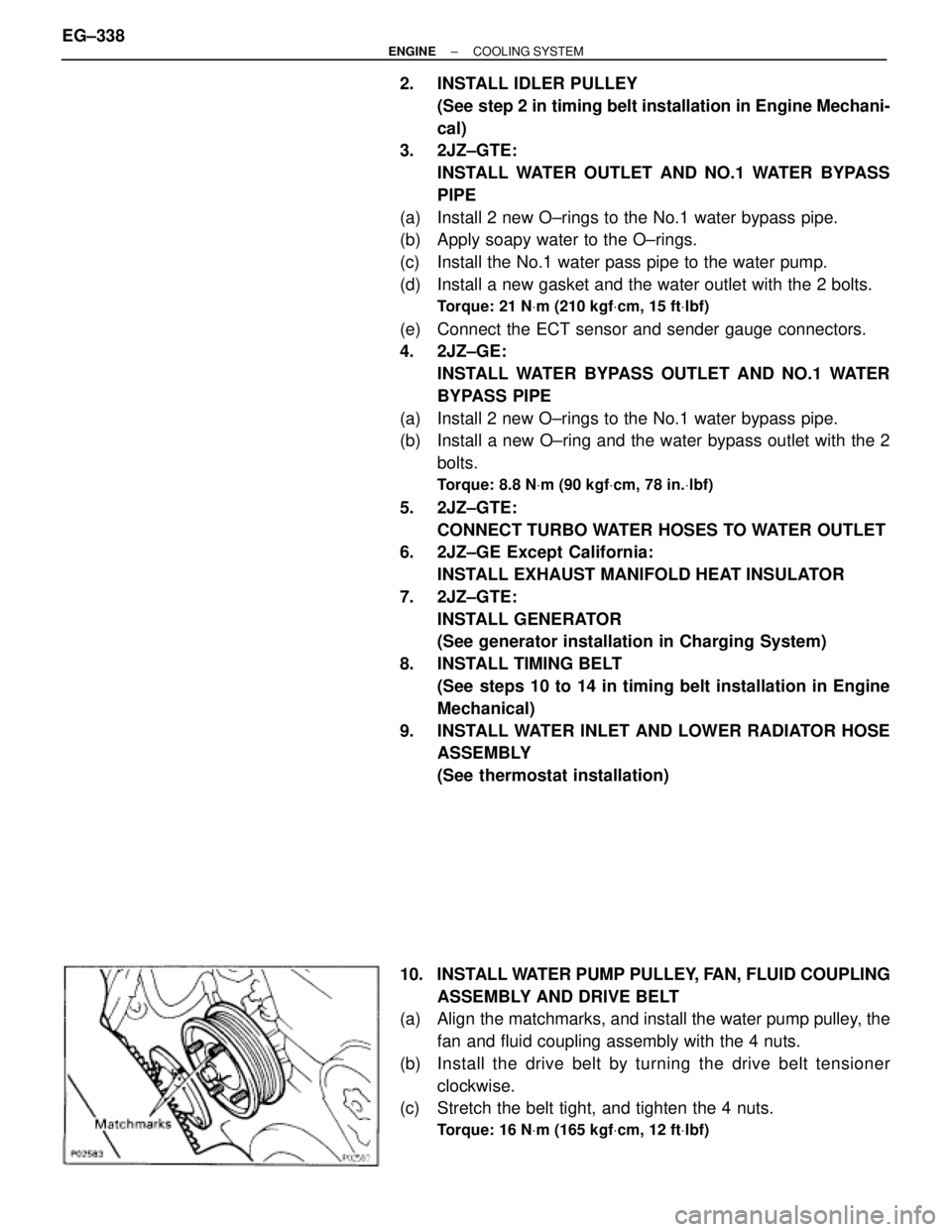
10. INSTALL WATER PUMP PULLEY, FAN, FLUID COUPLING
ASSEMBLY AND DRIVE BELT
(a) Align the matchmarks, and install the water pump pulley, the
fan and fluid coupling assembly with the 4 nuts.
(b) Install the drive belt by turning the drive belt tensioner
clockwise.
(c) Stretch the belt tight, and tighten the 4 nuts.
Torque: 16 NVm (165 kgfVcm, 12 ftVlbf)
EG±338± ENGINECOOLING SYSTEM
Page 584 of 878
THERMOSTAT REMOVAL
HINT: Removal of the thermostat would have an adverse ef-
fect, causing a lowering of cooling efficiency.
Do not remove the thermostat, even if the engine tends to
overheat.
1. 2JZ±GTE:
REMOVE ENGINE UNDER COVER
2. DRAIN ENGINE COOLANT
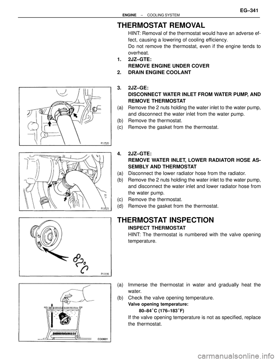
3. 2JZ±GE:
DISCONNECT WATER INLET FROM WATER PUMP, AND
REMOVE THERMOSTAT
(a) Remove the 2 nuts holding the water inlet to the water pump,
and disconnect the water inlet from the water pump.
(b) Remove the thermostat.
(c) Remove the gasket from the thermostat.
4. 2JZ±GTE:
REMOVE WATER INLET, LOWER RADIATOR HOSE AS-
SEMBLY AND THERMOSTAT
(a) Disconnect the lower radiator hose from the radiator.
(b) Remove the 2 nuts holding the water inlet to the water pump,
and disconnect the water inlet and lower radiator hose from
the water pump.
(c) Remove the thermostat.
(d) Remove the gasket from the thermostat.
THERMOSTAT INSPECTION
INSPECT THERMOSTAT
HINT: The thermostat is numbered with the valve opening
temperature.
(a) Immerse the thermostat in water and gradually heat the
water.
(b) Check the valve opening temperature.
Valve opening temperature:
80±84°C (176±183°F)
If the valve opening temperature is not as specified, replace
the thermostat.
± ENGINECOOLING SYSTEMEG±341
Page 586 of 878
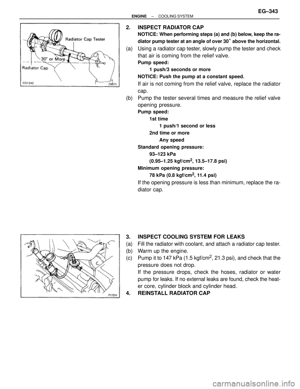
2. INSPECT RADIATOR CAP
NOTICE: When performing steps (a) and (b) below, keep the ra-
diator pump tester at an angle of over 30° above the horizontal.
(a) Using a radiator cap tester, slowly pump the tester and check
that air is coming from the relief valve.
Pump speed:
1 push/3 seconds or more
NOTICE: Push the pump at a constant speed.
If air is not coming from the relief valve, replace the radiator
cap.
(b) Pump the tester several times and measure the relief valve
opening pressure.
Pump speed:
1st time
1 push/1 second or less
2nd time or more
Any speed
Standard opening pressure:
93±123 kPa
(0.95±1.25 kgf/cm
2, 13.5±17.8 psi)
Minimum opening pressure:
78 kPa (0.8 kgf/cm
2, 11.4 psi)
If the opening pressure is less than minimum, replace the ra-
diator cap.
3. INSPECT COOLING SYSTEM FOR LEAKS
(a) Fill the radiator with coolant, and attach a radiator cap tester.
(b) Warm up the engine.
(c) Pump it to 147 kPa (1.5 kgf/cm
2, 21.3 psi), and check that the
pressure does not drop.
If the pressure drops, check the hoses, radiator or water
pump for leaks. If no external leaks are found, check the heat-
er core, cylinder block and cylinder head.
4. REINSTALL RADIATOR CAP
± ENGINECOOLING SYSTEMEG±343
Page 601 of 878
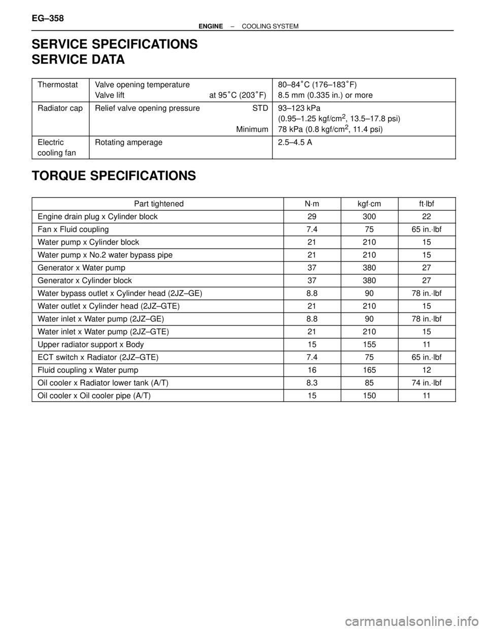
SERVICE SPECIFICATIONS
SERVICE DATA
������ �
����� ������
Thermostat���������������� �
��������������� ����������������
Valve opening temperature
Valve lift at 95°C (203°F)���������������� �
��������������� ����������������
80±84°C (176±183°F)
8.5 mm (0.335 in.) or more
������ �
����� �
����� ������
Radiator cap���������������� �
��������������� �
��������������� ����������������
Relief valve opening pressure STD
Minimum���������������� �
��������������� �
��������������� ����������������
93±123 kPa
(0.95±1.25 kgf/cm2, 13.5±17.8 psi)
78 kPa (0.8 kgf/cm
2, 11.4 psi)
������ �
����� ������
Electric
cooling fan���������������� �
��������������� ����������������
Rotating amperage���������������� �
��������������� ����������������
2.5±4.5 A
TORQUE SPECIFICATIONS
���������������������� ����������������������Part tightened����� �����NVm������ ������kgfVcm������ ������ftVlbf
���������������������� ����������������������Engine drain plug x Cylinder block����� �����29������ ������300������ ������22
���������������������� ����������������������Fan x Fluid coupling����� �����7.4������ ������75������ ������65 in.Vlbf
���������������������� ����������������������Water pump x Cylinder block����� �����21������ ������210������ ������15
���������������������� ����������������������Water pump x No.2 water bypass pipe����� �����21������ ������210������ ������15
���������������������� ����������������������Generator x Water pump����� �����37������ ������380������ ������27
���������������������� ����������������������Generator x Cylinder block����� �����37������ ������380������ ������27
���������������������� ����������������������Water bypass outlet x Cylinder head (2JZ±GE)����� �����8.8������ ������90������ ������78 in.Vlbf
���������������������� ����������������������Water outlet x Cylinder head (2JZ±GTE)����� �����21������ ������210������ ������15
���������������������� ����������������������Water inlet x Water pump (2JZ±GE)����� �����8.8������ ������90������ ������78 in.Vlbf
���������������������� ����������������������Water inlet x Water pump (2JZ±GTE)����� �����21������ ������210������ ������15���������������������� ����������������������Upper radiator support x Body����� �����15������ ������155������ ������11���������������������� ����������������������ECT switch x Radiator (2JZ±GTE)����� �����7.4������ ������75������ ������65 in.Vlbf���������������������� ����������������������Fluid coupling x Water pump����� �����16������ ������165������ ������12���������������������� ����������������������Oil cooler x Radiator lower tank (A/T)����� �����8.3������ ������85������ ������74 in.Vlbf���������������������� ����������������������Oil cooler x Oil cooler pipe (A/T)����� �����15������ ������150������ ������11
EG±358± ENGINECOOLING SYSTEM
Page 835 of 878
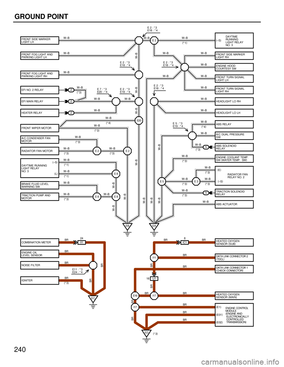
240
GROUND POINT
FRONT FOG LIGHT AND
PA RKING LIGHT RH
EFI NO. 2 RELAY
EFI MAIN RELAY
HEATER RELAY
FRONT WIPER MOTOR
A/C CONDENSER FAN
MOTOR
BRAKE FLUID LEVEL
WARNING SW
TRACTION PUMP AND
MOTOR
COMBINATION METER
ENGINE OIL
LEVEL SENSOR
NOISE FILTER
IGNITER FRONT FOG LIGHT AND
PARKING LIGHT LH FRONT SIDE MARKER
LIGHT LHDA YTIME
RUNNING
LIGHT RELAY
NO. 3
FRONT SIDE MARKER
LIGHT RH
ENGINE HOOD
COURTESY SW
FRONT TURN SIGNAL
LIGHT LH
FRONT TURN SIGNAL
LIGHT RH
HEADLIGHT LO RH
HEADLIGHT LO LH
ABS RELAY
A /C DUA L PRE SSURE
SW
ABS SOLENOID
RELAY
TRACTION SOLENOID
RELAY
A BS ACTUATOR E2
E5
E8 E8 E2 E2E2 0 2
2
2
5
5
EB EA
HEATED OXYGEN
SENSOR(
SUB)
HEATED OXYGEN
SENSOR(
MAIN)
ED EC II1 24
I17 E16 I 17I11
IJ1 18
(
E1)
(
E01)
(
E02) IC18 W±B
W±B
W±B
W±B W±B
W±B W±BW±B
W±B
W±B
W±B
W±B
W±B
BR
BR
BR
BRBR
BR W±BW±B
(
*4)
W±B
(
*3) W±B
(
*3)W±B
(
*1)
W±B
(
*4)
W±B
W±B
W±B
W±B
W±B
W±B W±BW±B W±B
BR BR
BR
BR
BR
BR
BR BR
BR BRBR
BR
W±B
(
*3)W±B
W±B
(
*3) E7 :*3
E20 : * 4E2:*3
E18 : * 4E2:*3
E18 : * 4
E2:*3
E18 :
*4
E5:*3
E19 : * 4
DAYTIME RUNNING
LIGHT RELAY
NO. 3 RADIATOR FAN MOTOR
E11 : * 3
E24 :
*4W±B
W±B
W±B W±B
W±B
(
*1)E2:*3
E18 : * 4
W±B
(
*3)
(
±S)(
±S)
DATA LINK CONNECTOR 2
(
TDCL)
DATA LINK CONNECTOR 1
(
CHECK CONNECTOR) RADIATOR FAN
RELAY NO. 2 (
E) ENGINE COOLANT TEMP.
SW(
WATER TEMP. SW)
(
±S)
E3
W±B W±B
W± B W± B W±B W±B
W±B
W± B
BR E2:*3
E18 : * 4
(
L)
E8 W±B
(
*1)
(
*3) (
*3)(
*3)
(
*3)
(
*3)(
*3)
(
*3)
(
*3)
(
*3)
ENGINE CONTROL
MODULE
(
ENGI NE AND
ELECTRONICALLY
CONTROLLED
TRANSMI SSION)
W±B