Page 56 of 878
 before the desired ignition
timing and outputs an ignition signa")
DTC 14 Ignition Signal Circuit
CIRCUIT DESCRIPTION
The ECM determines the ignition timing, turns on Tr1 at a predetermined angle (°CA) before the desired ignition
timing and outputs an ignition signal (IGT) º1º to the igniter.
Since the width of the IGT signal is constant, the dwell angle control circuit in the igniter determines the time
the control circuit starts primary current flow to the ignition coil based on the engine rpm and ignition timing one
revolution ago, that is, the time the Tr
2 turns on.
When it reaches the ignition timing, the ECM turns Tr
1 off and outputs the IGT signal ºOº.
This turns Tr
2 off, interrupting the primary current flow and generating a high voltage in the secondary coil which
causes the spark plug to spark. Also, by the counter electromotive force generated when the primary current
is interrupted, the igniter sends an ignition confirmation signal (IGF) to the ECM.
The ECM stops fuel injection as a fail safe function when the IGF signal is not input to the ECM.
����� �����DTC No.���������������� ����������������Diagnostic Trouble Code Detecting Condition����������������� �����������������Trouble Area����� �
���� �
���� �
���� �����
14
���������������� �
��������������� �
��������������� �
��������������� ����������������
No IGF signal to ECM for 4 ~ 7 consecutive
IGT signals with engine speed less than
3,000 rpm
����������������� �
���������������� �
���������������� �
���������������� �����������������
�Open or short in IGF circuit from igniter to
ECM
�Igniter
�ECM
± ENGINE2JZ±GTE ENGINE TROUBLESHOOTINGEG±519
Page 57 of 878
 Remove ignition coil. (See page IG±26)
(2) Remove spark plug.
(3) Install the spark plug to the ignition coil, and connect
the ignition coil connector.
(4) Ground the spark plug.")
Check for spark.
(1) Remove ignition coil. (See page IG±26)
(2) Remove spark plug.
(3) Install the spark plug to the ignition coil, and connect
the ignition coil connector.
(4) Ground the spark plug.
Check if spark occurs while engine is being cranked.
To prevent excess fuel being injected from injectors dur-
ing this test, don't crank the engine for more than 1Ð2
seconds at a time.
Check for open and short in harness and connector in IGF signal circuit
between engine control module and igniter (See page IN±30).
Repair or replace harness or connector.
Replace igniter.
Check and replace engine control module.
Disconnect igniter connector and check voltage between terminal IGF of
engine control module connector and body ground.
(1) Disconnect igniter connector.
(2) Connect SST (check harness ªAº).
(See page EG±510)
SST 09990±01000
(3) Turn ignition switch ON.
Measure voltage between terminal IGF of engine con-
trol module connector and body ground.
Voltage: 4.5 Ð 5.5 V
INSPECTION PROCEDURE
EG±520± ENGINE2JZ±GTE ENGINE TROUBLESHOOTING
Page 58 of 878
(See page EG±510)
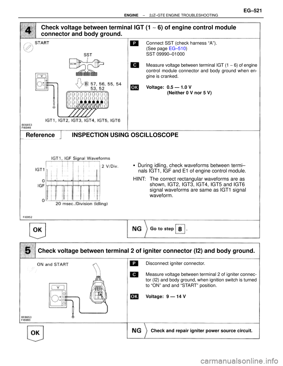
�During idling, check waveforms between termi±
nals IGT1, IGF and E1 of engine control module.
HINT: The correct rectangular waveforms are as
shown, IGT2, IGT3, IGT4, IGT5 and IGT6
signal waveforms are same as IGT1 signal
waveform.
Check voltage between terminal IGT (1 ~ 6) of engine control module
connector and body ground.
Connect SST (check harness ªAº).
(See page EG±510)
SST 09990±01000
Measure voltage between terminal IGT (1 ~ 6) of engine
control module connector and body ground when en-
gine is cranked.
Voltage: 0.5 Ð 1.0 V
(Neither 0 V nor 5 V)
Check voltage between terminal 2 of igniter connector (I2) and body ground.
Disconnect igniter connector.
Measure voltage between terminal 2 of igniter connec-
tor (I2) and body ground, when ignition switch is turned
to ªONº and and ªSTARTº position.
Voltage: 9 Ð 14 V
Check and repair igniter power source circuit.
ReferenceINSPECTION USING OSCILLOSCOPE
± ENGINE2JZ±GTE ENGINE TROUBLESHOOTINGEG±521
Page 59 of 878
Check for open and short in harness and connector between ignition
switch and ignition coil, ignition coil and igniter (See page IN±30).
Disconnect ignition coil connector.
(See page IG±23)
Measure resistance between terminals of ignition coil
connector.
Repair or replace harness or connector.
Check ignition coil.
ªColdº is from Ð 10°C (14°F) to 50°C (122°F) and ªHotº is
from 50°C (122°F) to 100°C (212°F).
Replace ignition coil.
Replace igniter.
EG±522± ENGINE2JZ±GTE ENGINE TROUBLESHOOTING
Page 61 of 878

DTC 16 A T Control Signal Malfunction
CIRCUIT DESCRIPTION
The signal from the A/T CPU retards the ignition timing of the engine during A/T gear shifting, thus momentarily
reducing torque output of the engine for smooth clutch operation inside the transmission and reduced shift
shock.
���� �
��� ����DTC No.
������������������ �
����������������� ������������������Diagnostic Trouble Code Detecting Condition
���������������� �
��������������� ����������������Trouble Area
���� �
��� ����16
������������������ �
����������������� ������������������
Fault in communications between the engine
CPU and A/T CPU in the ECM���������������� �
��������������� ���������������� � ECM
If the ECM detects the diagnostic trouble code º16º in memory, it prohibits the torque control of the A/T which
performs smooth gear shifting.
INSPECTION PROCEDURE
Are there any other codes (besides Code 16) being output?
Go to relevant diagnostic trouble code chart.
Replace engine control module.
EG±524± ENGINE2JZ±GTE ENGINE TROUBLESHOOTING
Page 68 of 878

(1) Connect SST (check harness ªAº).
(See page EG±510)
(2) Turn ignition switch ON
Measure voltage between terminals THW and
E2 of engine control module connector.
Check voltage")
(See page EG±510)
(1) Connect SST (check harness ªAº).
(See page EG±510)
(2) Turn ignition switch ON
Measure voltage between terminals THW and
E2 of engine control module connector.
Check voltage between terminals THW and E2 of engine control module
connector.
Check for intermittent problems.
(See page EG±505)
Disconnect the engine coolant temp. sensor con-
nector.
Measure resistance between terminals.
Resistance is within Acceptale Zone on chart.
Check engine coolant temp. sensor.
Replace engine coolant temp. sensor.
Repair or replace harness or connector.
Check and replace engine control module.
Check for open and short in harness and connector between engine control
module and engine coolant temp. sensor (See page IN±30).
INSPECTION PROCEDURE
HINT: If diagnostic trouble codes º22º (engine coolant temperature sensor circuit), º24º (intake air temperature
sensor circuit) and º41º (throttle position sensor circuit) are output simultaneously, E2 (sensor ground)
may be open.
± ENGINE2JZ±GTE ENGINE TROUBLESHOOTINGEG±531
Page 70 of 878

(1) Connect SST (check harness ªAº).
(See page EG±510)
SST 09990±01000
(2) Turn ignition switch ON
Measure voltage between terminals THW and E2
of engine control module connecto")
(See page EG±510)
(1) Connect SST (check harness ªAº).
(See page EG±510)
SST 09990±01000
(2) Turn ignition switch ON
Measure voltage between terminals THW and E2
of engine control module connector.
Check voltage between terminals THA and E2 of engine control module
connector.
Check for intermittent problems.
(See page EG±505)
Disconnect the mass air flow meter connector.
Measure resistance between terminals 3 and 4
of mass air flow meter connector.
Resistance is within Acceptable Zone on chart.
Check intake air temp. sensor.
Check for open and short in harness and connector between engine
control module and intake air temp. sensor (See page IN±30)
Replace intake air temp. sensor (Replace
mass air flow meter).
Repair or replace harness or connector.
Check and replace engine control module.
INSPECTION PROCEDURE
HINT: If diagnostic trouble codes º22º (engine coolant temperature sensor circuit), º24º (intake air temperature
sensor circuit) and º41º (throttle position sensor circuit) are output simultaneously, E2 (sensor ground)
may be open.
± ENGINE2JZ±GTE ENGINE TROUBLESHOOTINGEG±533
Page 71 of 878

DTC 25 26 Air±Fuel Ratio Lean Rich Malfunction
CIRCUIT DESCRIPTION
See EG±525 for the circuit description.
����� �����DTC No.���������������� ����������������Diagnostic Trouble Code Detecting Condition��������������� ���������������Trouble Area
����� �
���� �
���� �
���� �
���� �
���� �
���� �����
���������������� �
��������������� �
��������������� �
��������������� �
��������������� �
��������������� �
��������������� ����������������
(1) Main heated oxygen sensor voltage is
0.45 V or less (lean) for 90 sec. under
conditions (a) and (b):
(2 trip detection logic)*
2
(a) Engine coolant temp.: 70°C (158°F)
or more
(b) Engine speed: 1,500 rpm or more
��������������� �
�������������� �
�������������� �
�������������� �
�������������� �
�������������� �
�������������� ���������������
�Open or short in main heated oxygen
sensor circuit
�Main heated oxygen sensor
�Ignition system
�ECM
����� �
���� �
���� �
���� �
���� �
���� �
���� �
���� �����
25���������������� �
��������������� �
��������������� �
��������������� �
��������������� �
��������������� �
��������������� �
��������������� ����������������
(2) Engine speed varies by more than 20 rpm
over the preceding crank angle period
during a period of 25 sec. or more under
conditions (a) and (b):
(2 trip detection logic).*
(a) Engine speed: Below 950 rpm
(b) Engine coolant temp.: 80°C
(176°F) or
more��������������� �
�������������� �
�������������� �
�������������� �
�������������� �
�������������� �
�������������� �
�������������� ���������������
�Open and short in injector circuit
�Fuel line pressure (injector leak, blockage)
�Mechanical system malfunction
(skipping teeth of timing belt)
�Ignition system
�Compression pressure (foreign object
caught in valve)
�Mass air flow meter (air intake)
�ECM
����� �
���� �
���� �
���� �
���� �
���� �
���� �
���� �����
26
���������������� �
��������������� �
��������������� �
��������������� �
��������������� �
��������������� �
��������������� �
��������������� ����������������
Engine speed varies by more than 20 rpm over
The preceding crank angle period during a
Period of 25 sec. or more under conditions (a)
And (b):
(2 trip detection logic).*
(a) Engine speed: Below 950 rpm
(b) Engine coolant temp.: 80°C
(176°F) or
more��������������� �
�������������� �
�������������� �
�������������� �
�������������� �
�������������� �
�������������� �
�������������� ���������������
�Open and short in injector circuit
�Fuel line pressure (injector leak, blockage)
�Mechanical system malfunction
(skipping teeth of timing belt)
�Ignition system
�Compression pressure (foreign object
caught in valve)
�Mass air flow meter (air intake)
�ECM
*: See page EG±503. EG±534
± ENGINE2JZ±GTE ENGINE TROUBLESHOOTING
.
Disconnect ignition coil connector.
(See page IG±23)
Measure")