Page 79 of 878
INSPECTION PROCEDURE
HINT: When other codes are output in addition to 27 at the same time, check the circuits for other codes first.
(See page EG±510)
(1) Connect SST (check harness ªAº).
(See page EG±510)
SST 09990±01000
(2) Turn ignition switch ON.
Measure voltage between terminal HT2 of
engine control module connector and body
ground.
Voltage: 9 Ð 14 V
Check voltage between terminal HT2 of engine control module connector
and body ground.
EG±542± ENGINE2JZ±GTE ENGINE TROUBLESHOOTING
Page 82 of 878
(See page IN±30).
(See page EG±510)(1) Connect SST (check harness ªAº).
(See page EG±510)
SST 09990±01000
(2) Start engine.
Measure voltage between terminals VG and E21 of
engine control module connector while engine rpm
at idling.
Voltage: 0.7 Ð 1.7 V
Check voltage between terminal 1 of mass air flow meter connector and
body ground.
Check voltage between terminals VG and E21 of engine control module
connector.
Check and replace engine control module
Check for open and short in harness and connector between engine
control module and mass air flow meter (See page IN±30).
Check and repair mass air flow meter power
source circuit.
Repair or replace harness or connector.
Replace mass air flow meter.
(1) Disconnect the mass air flow meter connector.
(2) Turn ignition switch ON.
Measure voltage between terminal 1 of mass air
flow meter connector and body ground.
Voltage: 9 Ð 14 V
INSPECTION PROCEDURE
± ENGINE2JZ±GTE ENGINE TROUBLESHOOTINGEG±545
Page 85 of 878
(See page EG±510)
(1) Remove VSV.
(2) Disconnect VSV connector.
Check operation of VSV for waste gate valve when
battery positive voltage is applied and released to
the VSV terminals.
Battery positivie voltage is applied:
Air from port E is flowing out through port F.
Battery positive voltage is applied:
Closed air passage from E to F.
Check voltage terminals PMC of engine control module connector and
body ground.
Check operation of VSV for waste gate valve.
Replace VSV for waste gate valve.
Check and repair harness and connector be-
tween VSV for waste gate valve and engine
control module.
(1) Connect SST (check harness ªAº).
(See page EG±510)
SST 09990±01000
(2) Turn ignition switch ON.
Measure voltage between terminals PMC of engine
control module and ground.
Voltage: 9 Ð 14 V
Check and replace enginie control module. EG±548
± ENGINE2JZ±GTE ENGINE TROUBLESHOOTING
Page 87 of 878
(See page EG±510)(1) Connect SST (check harness ªAº).
(See page EG±510)
SST 09990±01000
(2) Turn ignition switch ON.
Measure voltage between terminals VCC and E1
of engine control module.
Voltage: 4.5 Ð 5.5 V
Check voltage between terminals VCC and E1 of engine control module
connector.
Check and replace engine control module.
INSPECTION PROCEDURE
HINT: DTC 35 indicates trouble in the BARO sensor circuit or turbo pressure sensor circuit. Because all func±
tions of the BARO sensor circuit are built into the ECM, it is not possible to check this circuit.
However, if no problem is found in the turbo pressure sensor circuit, it can be concluded that the problem
is in the BARO sensor circuit. EG±550
± ENGINE2JZ±GTE ENGINE TROUBLESHOOTING
Page 88 of 878
(See page IN±30).
Turn ignition switch ON.
Measure voltage between terminals PM1 and E2
of engine control module.
Voltage: 2.3 Ð 3.0 V
Check voltage between terminals PM1 and E2 of engine control module.
Check for open and short in harness and connector between engine control
module and turbo pressure sensor (See page
IN±30).
Check and replace engine control module.
Repair or replace harness or connector.
Replace turbo pressure sensor.
± ENGINE2JZ±GTE ENGINE TROUBLESHOOTINGEG±551
Page 91 of 878

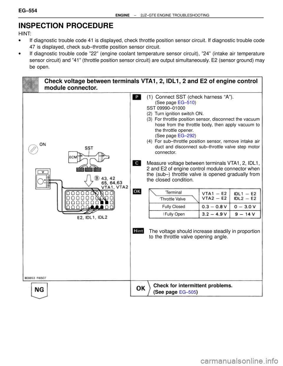
INSPECTION PROCEDURE
HINT:
wIf diagnostic trouble code 41 is displayed, check throttle position sensor circuit. If diagnostic trouble code
47 is displayed, check sub±throttle position sensor circuit.
wIf diagnostic trouble code º22º (engine coolant temperature sensor circuit), º24º (intake air temperature
sensor circuit) and º41º (throttle position sensor circuit) are output simultaneously. E2 (sensor ground) may
be open.
(See page EG±505)
(See page EG±510)
(See page EG±292)
Check voltage between terminals VTA1, 2, IDL1, 2 and E2 of engine control
module connector.
The voltage should increase steadily in proportion
to the throttle valve opening angle.
(1) Connect SST (check harness ªAº).
(See page EG±510)
SST 09990±01000
(2) Turn ignition switch ON.
(3) For throttle position sensor, disconnect the vacuum
hose from the throttle body, then apply vacuum to
the throttle opener.
(See page EG±292)
(4) For sub±throttle position sensor, remove intake air
duct and disconnect sub±throttle valve step motor
connector.
Measure voltage between terminals VTA1, 2, IDL1,
2 and E2 of engine control module connector when
the (sub±) throttle valve is opened gradually from
the closed condition.
Check for intermittent problems.
(See page
EG±505)
Throttle Valve
Terminal
Fully Closed
Fully Open
EG±554± ENGINE2JZ±GTE ENGINE TROUBLESHOOTING
Page 95 of 878
INSPECTION PROCEDURE
(See page EG±510)
(1) Shift the shift lever to N position.
(2) Jack up one of the rear wheels.
(3) Connect SST (check harness ªAº).
(See page
EG±510)
(4) Disconnect power steering ECU connector
and cruise control ECU connector.
(5) Turn ignition switch ON.
Measure voltage between terminal SP1 of engine
control module connector and body ground when
the wheel is turned slowly.
Voltage is generated intermittently.
Check voltage between terminal SP1 of engine control module connector
and body ground.
Check and replace engine control module.
Repair or replace harness or connector between
ECM and telltale light RH.
Repair or replace harness or connector between
telltale light RH and No.1 vehicle speed sensor.
Replace No.1 vehicle speed sensor.
Check operation of odometer and trip meter (telltale light RH
(See page Be±48)).
Check operation of No.1 vehicle speed sensor (See page BE±46).
EG±558± ENGINE2JZ±GTE ENGINE TROUBLESHOOTING
Page 96 of 878

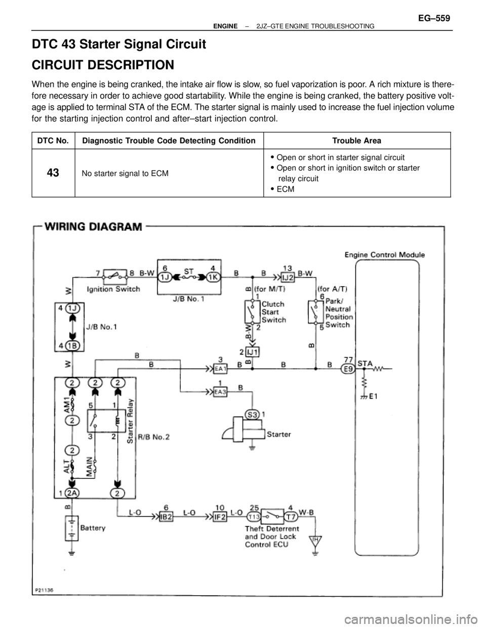
DTC 43 Starter Signal Circuit
CIRCUIT DESCRIPTION
When the engine is being cranked, the intake air flow is slow, so fuel vaporization is poor. A rich mixture is there-
fore necessary in order to achieve good startability. While the engine is being cranked, the battery positive volt-
age is applied to terminal STA of the ECM. The starter signal is mainly used to increase the fuel injection volume
for the starting injection control and after±start injection control.
����� �
���� �����DTC No.
���������������� �
��������������� ����������������Diagnostic Trouble Code Detecting Condition
���������������� �
��������������� ����������������Trouble Area
����� �
���� �
���� �
���� �����
43
���������������� �
��������������� �
��������������� �
��������������� ����������������
No starter signal to ECM
���������������� �
��������������� �
��������������� �
��������������� ����������������
�Open or short in starter signal circuit
�Open or short in ignition switch or starter
relay circuit
�ECM
± ENGINE2JZ±GTE ENGINE TROUBLESHOOTINGEG±559