Page 73 of 878
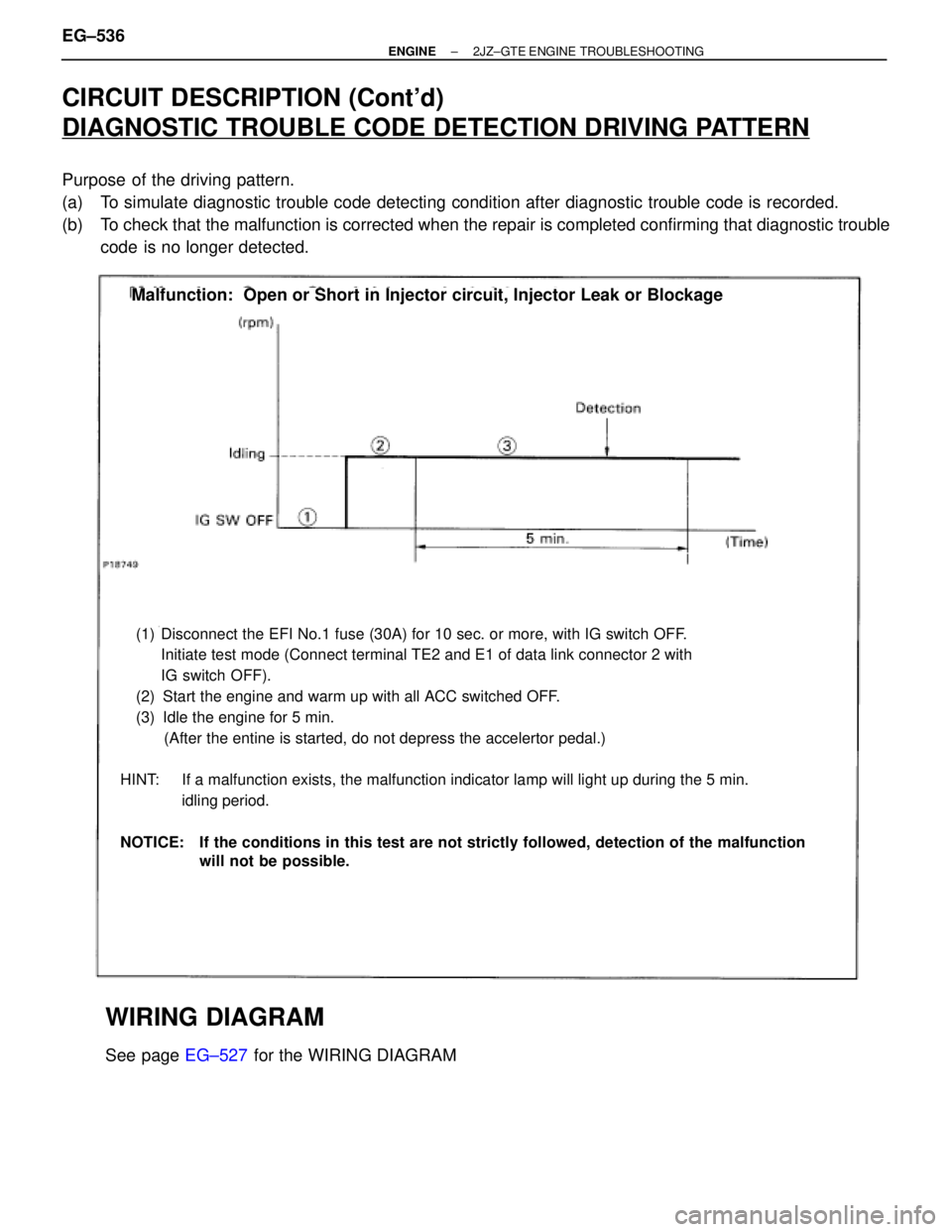
CIRCUIT DESCRIPTION (Cont'd)
DIAGNOSTIC TROUBLE CODE DETECTION DRIVING PATTERN
Purpose of the driving pattern.
(a) To simulate diagnostic trouble code detecting condition after diagnostic trouble code is recorded.
(b) To check that the malfunction is corrected when the repair is completed confirming that diagnostic trouble
code is no longer detected.
(1) Disconnect the EFI No.1 fuse (30A) for 10 sec. or more, with IG switch OFF.
Initiate test mode (Connect terminal TE2 and E1 of data link connector 2 with
IG switch OFF).
(2) Start the engine and warm up with all ACC switched OFF.
(3) Idle the engine for 5 min.
(After the entine is started, do not depress the accelertor pedal.)
HINT: If a malfunction exists, the malfunction indicator lamp will light up during the 5 min.
idling period.
NOTICE: If the conditions in this test are not strictly followed, detection of the malfunction
will not be possible.
Malfunction: Open or Short in Injector circuit, Injector Leak or Blockage
WIRING DIAGRAM
See page EG±527 for the WIRING DIAGRAM EG±536
± ENGINE2JZ±GTE ENGINE TROUBLESHOOTING
Page 78 of 878
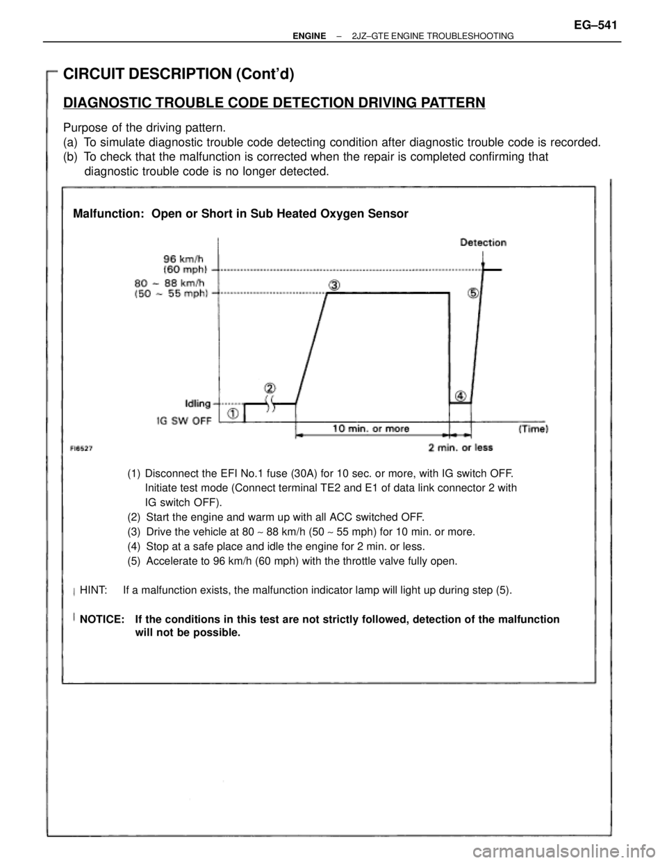
CIRCUIT DESCRIPTION (Cont'd)
DIAGNOSTIC TROUBLE CODE DETECTION DRIVING PATTERN
Purpose of the driving pattern.
(a) To simulate diagnostic trouble code detecting condition after diagnostic trouble code is recorded.
(b) To check that the malfunction is corrected when the repair is completed confirming that
diagnostic trouble code is no longer detected.
(1) Disconnect the EFI No.1 fuse (30A) for 10 sec. or more, with IG switch OFF.
Initiate test mode (Connect terminal TE2 and E1 of data link connector 2 with
IG switch OFF).
(2) Start the engine and warm up with all ACC switched OFF.
(3) Drive the vehicle at 80 ~ 88 km/h (50 ~ 55 mph) for 10 min. or more.
(4) Stop at a safe place and idle the engine for 2 min. or less.
(5) Accelerate to 96 km/h (60 mph) with the throttle valve fully open.
HINT: If a malfunction exists, the malfunction indicator lamp will light up during step (5).
NOTICE: If the conditions in this test are not strictly followed, detection of the malfunction
will not be possible.
Malfunction: Open or Short in Sub Heated Oxygen Sensor
± ENGINE2JZ±GTE ENGINE TROUBLESHOOTINGEG±541
Page 86 of 878
DTC 35 Turbo Pressure Sensor Circuit Barometric Pressure (BARO)
Sensor Circuit
CIRCUIT DESCRIPTION
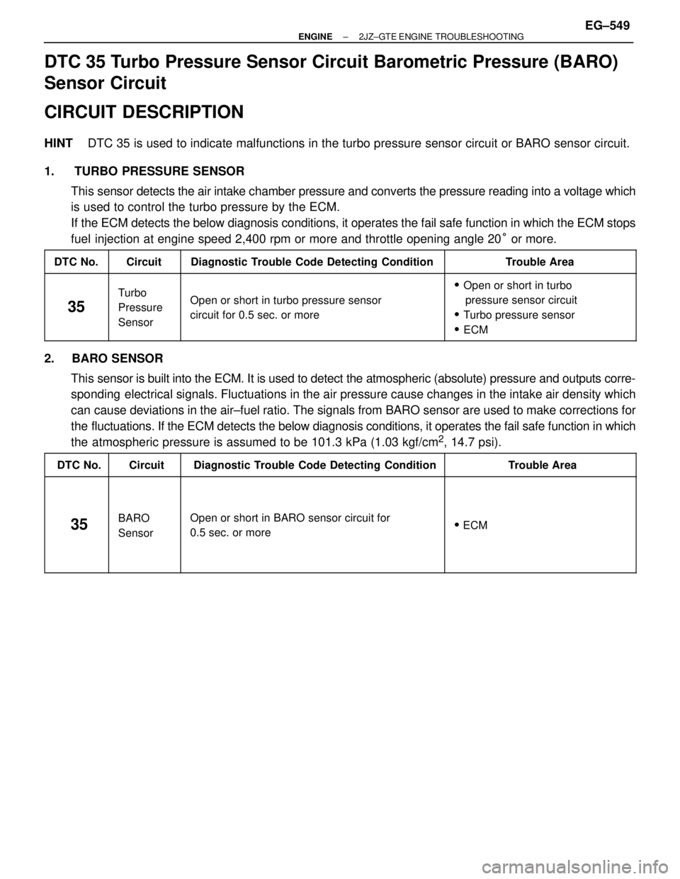
HINT DTC 35 is used to indicate malfunctions in the turbo pressure sensor circuit or BARO sensor circuit.
1. TURBO PRESSURE SENSOR
This sensor detects the air intake chamber pressure and converts the pressure reading into a voltage which
is used to control the turbo pressure by the ECM.
If the ECM detects the below diagnosis conditions, it operates the fail safe function in which the ECM stops
fuel injection at engine speed 2,400 rpm or more and throttle opening angle 20° or more.
����� �
���� �����DTC No.����� �
���� �����Circuit����������������� �
���������������� �����������������Diagnostic Trouble Code Detecting Condition������������ �
����������� ������������Trouble Area
����� �
���� �
���� �
���� �����
35
����� �
���� �
���� �
���� �����
Turbo
Pressure
Sensor����������������� �
���������������� �
���������������� �
���������������� �����������������
Open or short in turbo pressure sensor
circuit for 0.5 sec. or more
������������ �
����������� �
����������� �
����������� ������������
�Open or short in turbo
pressure sensor circuit
�Turbo pressure sensor
�ECM
2. BARO SENSOR
This sensor is built into the ECM. It is used to detect the atmospheric (absolute) pressure and outputs corre-
sponding electrical signals. Fluctuations in the air pressure cause changes in the intake air density which
can cause deviations in the air±fuel ratio. The signals from BARO sensor are used to make corrections for
the fluctuations. If the ECM detects the below diagnosis conditions, it operates the fail safe function in which
the atmospheric pressure is assumed to be 101.3 kPa (1.03 kgf/cm
2, 14.7 psi).
����� �����DTC No.����� �����Circuit����������������� �����������������Diagnostic Trouble Code Detecting Condition������������ ������������Trouble Area����� �
���� �
���� �
���� �
���� �
���� �����
35
����� �
���� �
���� �
���� �
���� �
���� �����
BARO
Sensor
����������������� �
���������������� �
���������������� �
���������������� �
���������������� �
���������������� �����������������
Open or short in BARO sensor circuit for
0.5 sec. or more
������������ �
����������� �
����������� �
����������� �
����������� �
����������� ������������
� ECM
± ENGINE2JZ±GTE ENGINE TROUBLESHOOTINGEG±549
Page 89 of 878
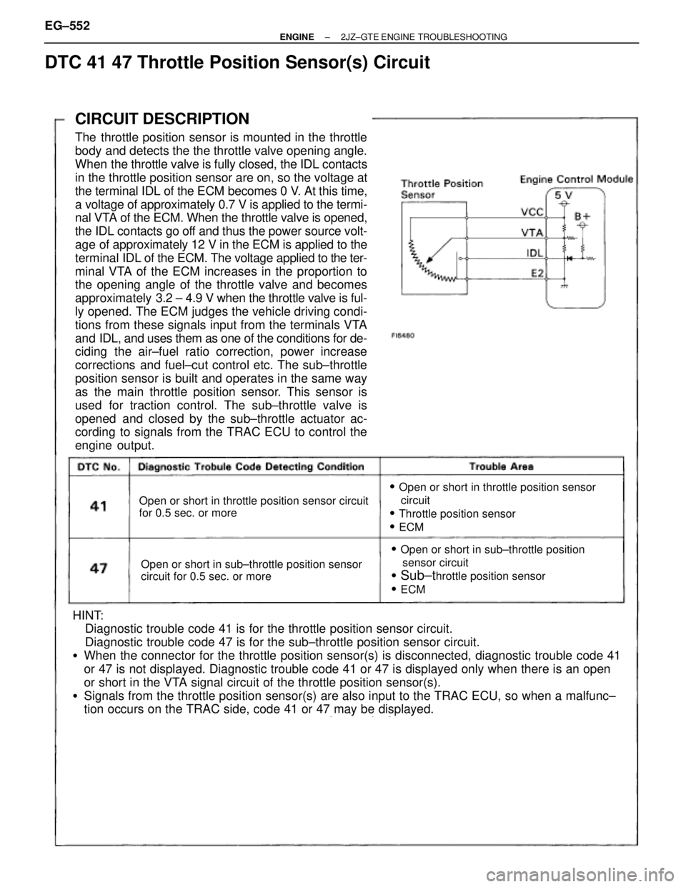
CIRCUIT DESCRIPTION
The throttle position sensor is mounted in the throttle
body and detects the the throttle valve opening angle.
When the throttle valve is fully closed, the IDL contacts
in the throttle position sensor are on, so the voltage at
the terminal IDL of the ECM becomes 0 V. At this time,
a voltage of approximately 0.7 V is applied to the termi-
nal VTA of the ECM. When the throttle valve is opened,
the IDL contacts go off and thus the power source volt-
age of approximately 12 V in the ECM is applied to the
terminal IDL of the ECM. The voltage applied to the ter-
minal VTA of the ECM increases in the proportion to
the opening angle of the throttle valve and becomes
approximately 3.2 ± 4.9 V when the throttle valve is ful-
ly opened. The ECM judges the vehicle driving condi-
tions from these signals input from the terminals VTA
and IDL, and uses them as one of the conditions for de-
ciding the air±fuel ratio correction, power increase
corrections and fuel±cut control etc. The sub±throttle
position sensor is built and operates in the same way
as the main throttle position sensor. This sensor is
used for traction control. The sub±throttle valve is
opened and closed by the sub±throttle actuator ac-
cording to signals from the TRAC ECU to control the
engine output.
Open or short in throttle position sensor circuit
for 0.5 sec. or more
Open or short in sub±throttle position sensor
circuit for 0.5 sec. or more
�Open or short in throttle position sensor
circuit
�Throttle position sensor
�ECM
�Open or short in sub±throttle position
sensor circuit
�Sub±throttle position sensor
�ECM
HINT:
Diagnostic trouble code 41 is for the throttle position sensor circuit.
Diagnostic trouble code 47 is for the sub±throttle position sensor circuit.
�When the connector for the throttle position sensor(s) is disconnected, diagnostic trouble code 41
or 47 is not displayed. Diagnostic trouble code 41 or 47 is displayed only when there is an open
or short in the VTA signal circuit of the throttle position sensor(s).
�Signals from the throttle position sensor(s) are also input to the TRAC ECU, so when a malfunc±
tion occurs on the TRAC side, code 41 or 47 may be displayed.
DTC 41 47 Throttle Position Sensor(s) Circuit
EG±552± ENGINE2JZ±GTE ENGINE TROUBLESHOOTING
Page 91 of 878
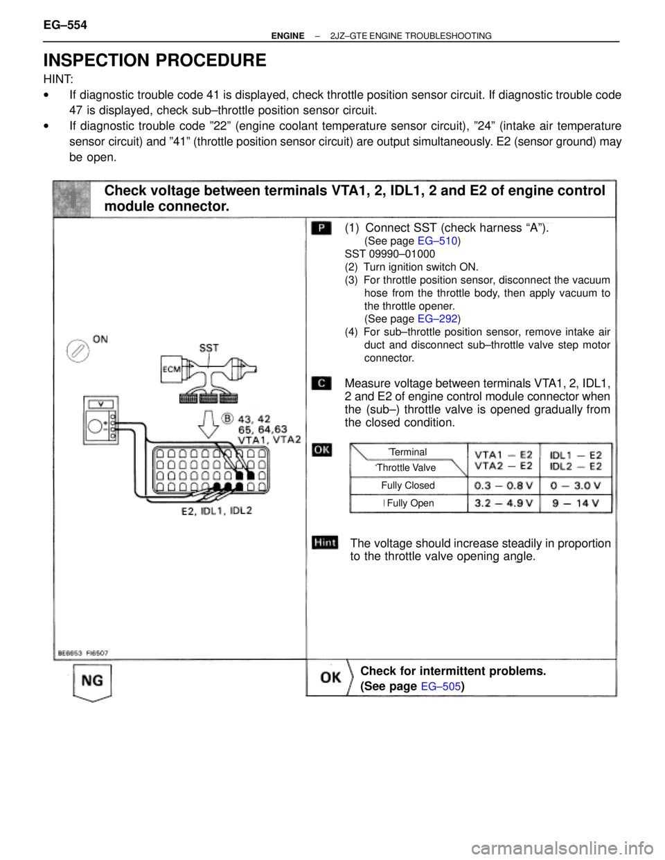
INSPECTION PROCEDURE
HINT:
wIf diagnostic trouble code 41 is displayed, check throttle position sensor circuit. If diagnostic trouble code
47 is displayed, check sub±throttle position sensor circuit.
wIf diagnostic trouble code º22º (engine coolant temperature sensor circuit), º24º (intake air temperature
sensor circuit) and º41º (throttle position sensor circuit) are output simultaneously. E2 (sensor ground) may
be open.
(See page EG±505)
(See page EG±510)
(See page EG±292)
Check voltage between terminals VTA1, 2, IDL1, 2 and E2 of engine control
module connector.
The voltage should increase steadily in proportion
to the throttle valve opening angle.
(1) Connect SST (check harness ªAº).
(See page EG±510)
SST 09990±01000
(2) Turn ignition switch ON.
(3) For throttle position sensor, disconnect the vacuum
hose from the throttle body, then apply vacuum to
the throttle opener.
(See page EG±292)
(4) For sub±throttle position sensor, remove intake air
duct and disconnect sub±throttle valve step motor
connector.
Measure voltage between terminals VTA1, 2, IDL1,
2 and E2 of engine control module connector when
the (sub±) throttle valve is opened gradually from
the closed condition.
Check for intermittent problems.
(See page
EG±505)
Throttle Valve
Terminal
Fully Closed
Fully Open
EG±554± ENGINE2JZ±GTE ENGINE TROUBLESHOOTING
Page 92 of 878
(1) Remove throttle body. (See page EG±291)
(2) For throttle position sensor, apply vacuum to
throttle opener. (See page
EG±292)
Measure resistance of each terminal as below table
when the throttle valve is opened gradually from the
closed condition.
Check throttle position sensor(s).
Check for open and short in harness and connector between engine control
module and throttle position sensors(s) (See page
IN±30).
Resistance between terminals 2,3 (VTA1,2) and 4,1
(E2) should increase gradually in accordance with
the throttle valve opening angle.
Adjust or replace throttle position sensor(s).
(See page EG±292)
Repair or replace harness or connector.
Check and replace engine control module.
For Throttle Position Sensor
For Sub±Throttle Position Sensor
Throttle Valve
Terminal
Throttle
Position
Sensor
Sub throttle
Position
Sensor
Fully
Closed Fully
Opened
± ENGINE2JZ±GTE ENGINE TROUBLESHOOTINGEG±555
Page 96 of 878
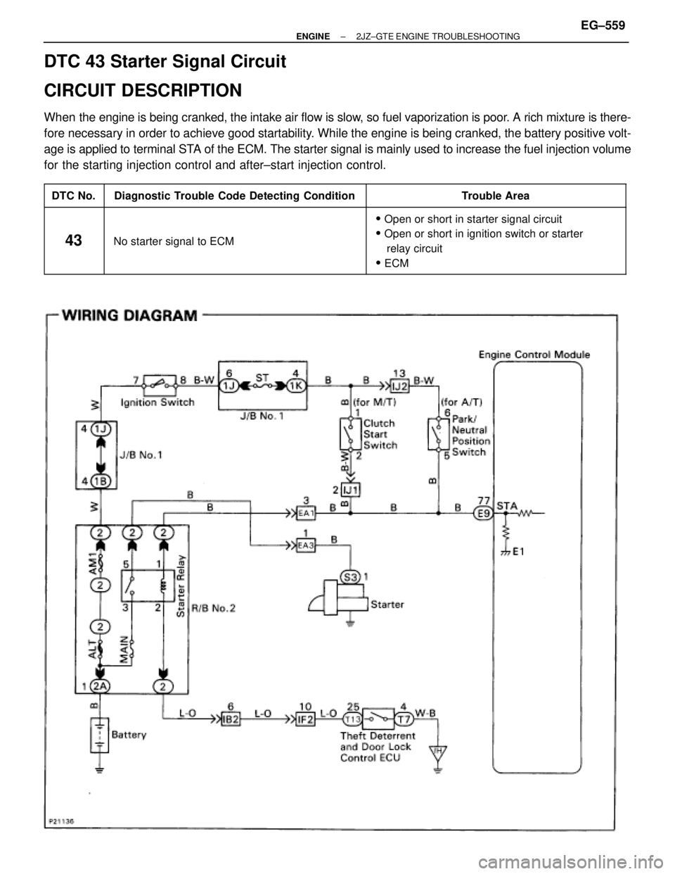
DTC 43 Starter Signal Circuit
CIRCUIT DESCRIPTION
When the engine is being cranked, the intake air flow is slow, so fuel vaporization is poor. A rich mixture is there-
fore necessary in order to achieve good startability. While the engine is being cranked, the battery positive volt-
age is applied to terminal STA of the ECM. The starter signal is mainly used to increase the fuel injection volume
for the starting injection control and after±start injection control.
����� �
���� �����DTC No.
���������������� �
��������������� ����������������Diagnostic Trouble Code Detecting Condition
���������������� �
��������������� ����������������Trouble Area
����� �
���� �
���� �
���� �����
43
���������������� �
��������������� �
��������������� �
��������������� ����������������
No starter signal to ECM
���������������� �
��������������� �
��������������� �
��������������� ����������������
�Open or short in starter signal circuit
�Open or short in ignition switch or starter
relay circuit
�ECM
± ENGINE2JZ±GTE ENGINE TROUBLESHOOTINGEG±559
Page 97 of 878
INSPECTION PROCEDURE
HINT: This diagnostic chart is based on the premise that the engine is being cranked under normal conditions.
If the engine does not crank, proceed to the matrix chart of problem symptoms on page EG±514.
(See page EG±514).
Setting the test mode.
(1) Turn ignition switch OFF.
(2) Connect terminals TE2 and E1 of DLC2.
(3) Turn ignition switch ON.
(Don't start the engine)
(4) Connect terminal TE1 and E1 of DLC2.
Check if code ª43º is output by the malfunction indi-
cator lamp.
Code ª43º is output.
Start the engine.
Check if code ª43º disappears.
Code ª43º is not output.
Check output condition of diagnostic trouble code 43.
Proceed to next circuit inspection shown on
matrix chart (See page Eg±514.)
Check and replace engine control module.
Check for open in harness and connector between engine control module
and starter relay (See page IN±30).
Repair or replace harness or connector.
EG±560± ENGINE2JZ±GTE ENGINE TROUBLESHOOTING