Page 27 of 3115

AC1LQ-04
I08494
AC-90
- AIR CONDITIONINGAIR INLET TEMPERATURE SENSOR
2815 Author�: Date�:
2004 LAND CRUISER (RM1071U)
AIR INLET TEMPERATURE
SENSOR
INSPECTION
1. REMOVE FRONT SEATS
2. REMOVE REAR CONSOLE BOX
3. REMOVE FRONT CONSOLE BOX COVER
4. REMOVE LOWER CENTER CLUSTER FINISH PANEL
5. REMOVE FRONT DOOR SCUFF PLATES
6. REMOVE COWL SIDE TRIMS
7. REMOVE REAR DOOR SCUFF PATES
8. REMOVE CENTER PILLAR GARNISHES
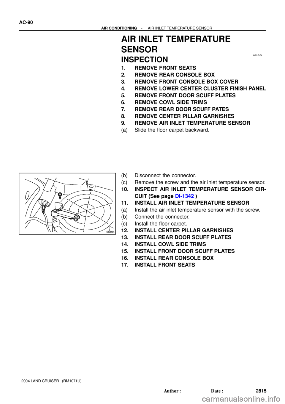
9. REMOVE AIR INLET TEMPERATURE SENSOR
(a) Slide the floor carpet backward.
(b) Disconnect the connector.
(c) Remove the screw and the air inlet temperature sensor.
10. INSPECT AIR INLET TEMPERATURE SENSOR CIR-
CUIT (See page DI-1342)
11. INSTALL AIR INLET TEMPERATURE SENSOR
(a) Install the air inlet temperature sensor with the screw.
(b) Connect the connector.
(c) Install the floor carpet.
12. INSTALL CENTER PILLAR GARNISHES
13. INSTALL REAR DOOR SCUFF PLATES
14. INSTALL COWL SIDE TRIMS
15. INSTALL FRONT DOOR SCUFF PLATES
16. INSTALL REAR CONSOLE BOX
17. INSTALL FRONT SEATS
Page 81 of 3115

AC1LJ-04
I06818
- AIR CONDITIONINGPOWER TRANSISTOR (for Rear Heater)
AC-83
2808 Author�: Date�:
2004 LAND CRUISER (RM1071U)
POWER TRANSISTOR (for Rear
Heater)
INSPECTION
1. REMOVE FRONT SEATS
2. REMOVE REAR CONSOLE BOX
3. REMOVE FRONT CONSOLE BOX COVER
4. REMOVE LOWER CENTER CLUSTER FINISH PANEL
5. REMOVE FRONT DOOR SCUFF PLATES
6. REMOVE COWL SIDE TRIMS
7. REMOVE REAR DOOR SCUFF PATES
8. REMOVE CENTER PILLAR GARNISHES
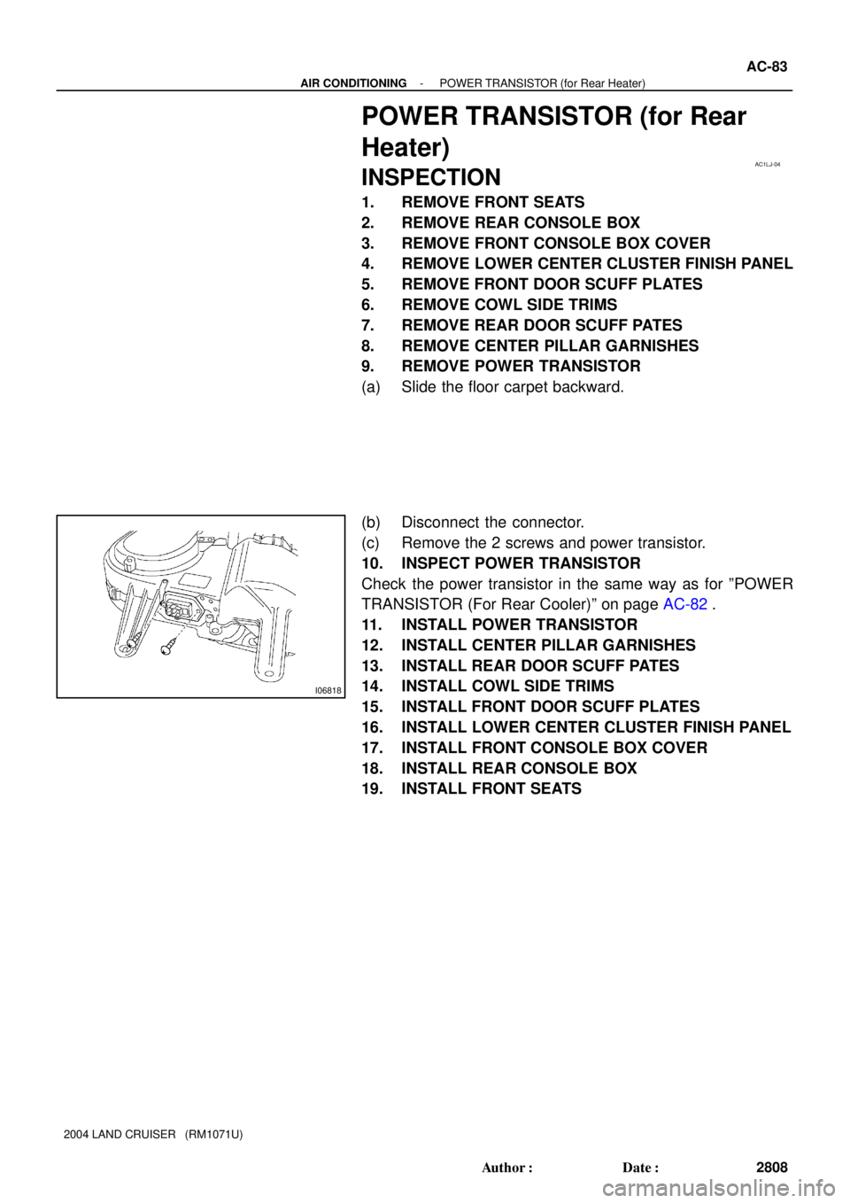
9. REMOVE POWER TRANSISTOR
(a) Slide the floor carpet backward.
(b) Disconnect the connector.
(c) Remove the 2 screws and power transistor.
10. INSPECT POWER TRANSISTOR
Check the power transistor in the same way as for ºPOWER
TRANSISTOR (For Rear Cooler)º on page AC-82.
11. INSTALL POWER TRANSISTOR
12. INSTALL CENTER PILLAR GARNISHES
13. INSTALL REAR DOOR SCUFF PATES
14. INSTALL COWL SIDE TRIMS
15. INSTALL FRONT DOOR SCUFF PLATES
16. INSTALL LOWER CENTER CLUSTER FINISH PANEL
17. INSTALL FRONT CONSOLE BOX COVER
18. INSTALL REAR CONSOLE BOX
19. INSTALL FRONT SEATS
Page 109 of 3115
AC1KO-04
I03973
I05080
Second Ridge
Hose Clip
Water Hose
I03924
- AIR CONDITIONINGREAR HEATER UNIT
AC-47
2772 Author�: Date�:
2004 LAND CRUISER (RM1071U)
REMOVAL
1. DRAIN ENGINE COOLANT FROM RADIATOR
HINT:
It is not necessary to drain out all the coolant.
2. DISCONNECT WATER HOSES FROM HEATER RA-
DIATOR PIPES
(a) Using pliers, grip the claws of the clip and slide the clip
along the hose
(b) Disconnect the water hoses
HINT:
At the time of installation, push the water hose on to the heater
radiator pipe to the second ridge on the pipe.
3. REMOVE FRONT SEATS
4. REMOVE REAR CONSOLE BOX
5. REMOVE FRONT CONSOLE BOX COVER
6. REMOVE LOWER CENTER CLUSTER FINISH PANEL
7. REMOVE FRONT DOOR SCUFF PLATE
8. REMOVE COWL SIDE TRIMS
9. REMOVE REAR DOOR SCUFF PLATES
10. REMOVE CENTER PILLAR GARNISHES
11. SLIDE FLOOR CARPET BACKWARD
12. REMOVE COOLER BRACKET
Remove the 4 bolts and the cooler bracket.
Page 381 of 3115
BO1JA-04
H20972
Door Glass Run Door Glass
Outside Handle
Door Lock Cylinder
Door Lock
Window RegulatorLower FrameDoor Belt Moulding
Tweeter Speaker
Lower Frame
Bracket Garnish Outside Rear View Mirror
Service
Hole Cover Door Inside
Handle Bezel
No. 1Inside Handle
Door Courtesy Light
Door TrimSpeaker
Door Hinge Door Check
5.0 (51, 44 in.´lbf)
5.0 (51, 44 in.´lbf)
26 (265, 19)
26 (265, 19)
�
: Specified torqueN´m (kgf´cm, ft´lbf)
� Precoated part
8.0 (82, 71 in.´lbf)
27 (275, 20)
5.0 (51, 44 in.´lbf)
Power Window Switch
Door Lock Link
Protector
8.0 (82, 71 in.´lbf)
8.0 (82, 71 in.´lbf)Door Inside
Handle Bezel No. 2
Door Check Cover
8.0 (82, 71 in.´lbf)
8.0 (82, 71 in.´lbf)
5.0 (51, 44 in.´lbf)
23 (235, 17)
23 (235, 17)
BO-8
- BODYFRONT DOOR
2582 Author�: Date�:
2004 LAND CRUISER (RM1071U)
FRONT DOOR
COMPONENTS
Page 420 of 3115
2 Clips
H21279
H18904
- BODYINSTRUMENT PANEL
BO-95
2669 Author�: Date�:
2004 LAND CRUISER (RM1071U)
28. INSTALL CLUSTER FINISH PANEL
Connect the connecter, then install the cluster finish panel.
29. INSTALL STEERING WHEEL
(See page SR-24 or SR-37)
30. INSTALL FRONT PILLAR GARNISH
(a) Install the front pillar garnish.
(b) Use the same manner described above to the other side.
31. INSTALL FRONT ASSIST GRIP
(a) Install the assist grip with the 2 screws, then install the 2
assist grip plugs.
(b) Use the same manner described above to the other side.
32. INSTALL FRONT DOOR OPENING TRIMS
33. INSTALL COWL SIDE TRIMS
34. INSTALL FRONT DOOR SCUFF PLATES
Page 422 of 3115

BO4IX-01
H20976
H20977
H20975
: 8 Clips
H20978
BO-84
- BODYINSTRUMENT PANEL
2658 Author�: Date�:
2004 LAND CRUISER (RM1071U)
REMOVAL
1. w/ CD Changer Built In The Audio System:
SHIP MODE SETTING
(a) Take out all of the CDs.
NOTICE:
If they cannot be taken out, do not attempt to take out forci-
bly and send the unit for repair.
(b) Turn the ignition switch to ACC as pressing the ºSEEK
UPº and ºDISCº switches at the same time.
HINT:
When the ship mode has been set, ºSHIPº must be displayed.
(c) Turn the ignition switch to OFF and disconnect the battery
negative cable.
NOTICE:
Connecting the battery negative cable automatically end
the ship mode.
2. REMOVE CENTER REGISTER
(a) Using a moulding remover, remove the center register.
(b) Disconnect the connector.
(c) Use the same manner described above to the other side.
3. REMOVE RADIO WITH A/C CONTROL ASSEMBLY
(a) Remove the 4 bolts.
(b) Disconnect the radio with A/C control assembly cable and
remove the radio with A/C control assembly.
4. w/ CD Changer Built In The Audio System:
SHIP MODE CONFIRMATION
Check that a metal can be seen from holes marked ºSHIPº on
the back of the radio with A/C control assembly.
NOTICE:
If a metal cannot be seen from a hole on the back of the ra-
dio with A/C control assembly, repeat ºSHIP MODEº.
5. REMOVE FRONT DOOR SCUFF PLATES
6. REMOVE COWL SIDE TRIMS
7. REMOVE FRONT DOOR OPENING TRIMS
Page 467 of 3115

BO4IZ-01
H05257
: 5 Clips
H05258
H05259
H07941
11 Clips
- BODYROOF HEADLINING
BO-97
2671 Author�: Date�:
2004 LAND CRUISER (RM1071U)
REMOVAL
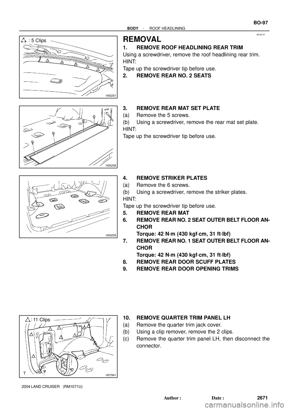
1. REMOVE ROOF HEADLINING REAR TRIM
Using a screwdriver, remove the roof headlining rear trim.
HINT:
Tape up the screwdriver tip before use.
2. REMOVE REAR NO. 2 SEATS
3. REMOVE REAR MAT SET PLATE
(a) Remove the 5 screws.
(b) Using a screwdriver, remove the rear mat set plate.
HINT:
Tape up the screwdriver tip before use.
4. REMOVE STRIKER PLATES
(a) Remove the 6 screws.
(b) Using a screwdriver, remove the striker plates.
HINT:
Tape up the screwdriver tip before use.
5. REMOVE REAR MAT
6. REMOVE REAR NO. 2 SEAT OUTER BELT FLOOR AN-
CHOR
Torque: 42 N´m (430 kgf´cm, 31 ft´lbf)
7. REMOVE REAR NO. 1 SEAT OUTER BELT FLOOR AN-
CHOR
Torque: 42 N´m (430 kgf´cm, 31 ft´lbf)
8. REMOVE REAR DOOR SCUFF PLATES
9. REMOVE REAR DOOR OPENING TRIMS
10. REMOVE QUARTER TRIM PANEL LH
(a) Remove the quarter trim jack cover.
(b) Using a clip remover, remove the 2 clips.
(c) Remove the quarter trim panel LH, then disconnect the
connector.
Page 468 of 3115

H18922
10 Clips
H18906
: 9 Clips
H18904
H05264
Claw
BO-98
- BODYROOF HEADLINING
2672 Author�: Date�:
2004 LAND CRUISER (RM1071U)
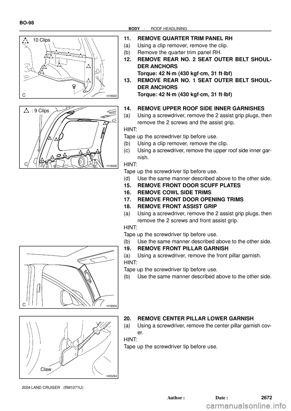
11. REMOVE QUARTER TRIM PANEL RH
(a) Using a clip remover, remove the clip.
(b) Remove the quarter trim panel RH.
12. REMOVE REAR NO. 2 SEAT OUTER BELT SHOUL-
DER ANCHORS
Torque: 42 N´m (430 kgf´cm, 31 ft´lbf)
13. REMOVE REAR NO. 1 SEAT OUTER BELT SHOUL-
DER ANCHORS
Torque: 42 N´m (430 kgf´cm, 31 ft´lbf)
14. REMOVE UPPER ROOF SIDE INNER GARNISHES
(a) Using a screwdriver, remove the 2 assist grip plugs, then
remove the 2 screws and the assist grip.
HINT:
Tape up the screwdriver tip before use.
(b) Using a clip remover, remove the clip.
(c) Using a screwdriver, remove the upper roof side inner gar-
nish.
HINT:
Tape up the screwdriver tip before use.
(d) Use the same manner described above to the other side.
15. REMOVE FRONT DOOR SCUFF PLATES
16. REMOVE COWL SIDE TRIMS
17. REMOVE FRONT DOOR OPENING TRIMS
18. REMOVE FRONT ASSIST GRIP
(a) Using a screwdriver, remove the 2 assist grip plugs, then
remove the 2 screws and front assist grip.
HINT:
Tape up the screwdriver tip before use.
(b) Use the same manner described above to the other side.
19. REMOVE FRONT PILLAR GARNISH
(a) Using a screwdriver, remove the front pillar garnish.
HINT:
Tape up the screwdriver tip before use.
(b) Use the same manner described above to the other side.
20. REMOVE CENTER PILLAR LOWER GARNISH
(a) Using a screwdriver, remove the center pillar garnish cov-
er.
HINT:
Tape up the screwdriver tip before use.